OMS Workhorse R236C User manual

OWNER'S MANUAL
Item numbers:
R236C
R-239
OMS LLC
WORKHORSE
REGULATOR

CE Approved OMS Workhorse Regulator
You purchased the right Regulator!
It is important to pay special attention to information provided in warnings, cautions and
notes, which are accompanied by the following symbols:
A indicates any situation that, if not avoided, could result in
serious injury or death
A indicates any situation or technique that could cause damage
to the product, and could subsequently result in injury to the user.
A is used to emphasize important points or reminders.
Use of SCUBA equipment by uncertified, or untrained persons, is dangerous and
can result in serious injury, or death.
Before using your OMS Workhorse Regulator, you must have successfully completed
a training and certification course in the techniques of SCUBA diving from a recognized
certification agency (or any U. S. Military or government operated diving school). Use of
OMS Workhorse Regulator by any person who is not certified by a recognized agency
shall render all warranties, expressed or implied, null and void.
The OMS Workhorse Regulator is not configured for use with surface supplied air
Always pressurize the Workhorse Regulator gradually by opening the cylinder valve
slowly.
Never lubricate any part of the Workhorse Regulator or cylinder valve with any
lubricant. Only an OMS trained technician is qualified to do lubrication.
t
DO NOT apply any type of aerosol lubricant spray or any aerosol spray on the
Workhorse Regulator. Doing so may cause permanent damage to certain plastic parts,
including the second-stage housing.
NEVER leave the cylinder standing unsecured with the Workhorse Regulator attached
to the valve as this may cause permanent damage to the Workhorse Regulator and
cylinder valve if the cylinder accidentally falls.
Do not use oxygen mixtures of gas exceeding a maximum pressure of 2640 psi as
serious personal injury or death could result from fire or explosion.
®
Table of Contents
Introduction
WARNING
CAUTION
NOTE
General Precautions and Warnings
Introduction 1
Warnings and Precautions 1
Mounting the First Stage with DIN or Yoke Adapter 2
Pre-Dive Checkout 3
Inspection Checklist 3
Anti Freeze Protection 4
Use of regulator with Oxygen 4
Post Dive Care and Maintenance 4
Required Maintenance 5
Dealer Inspection and Service 6
Warranty Information 7
1.
2.
3.
4.
5.
6.
7.
8.
®
®
®
R-239 Yoke Adapter
(Optional)
1

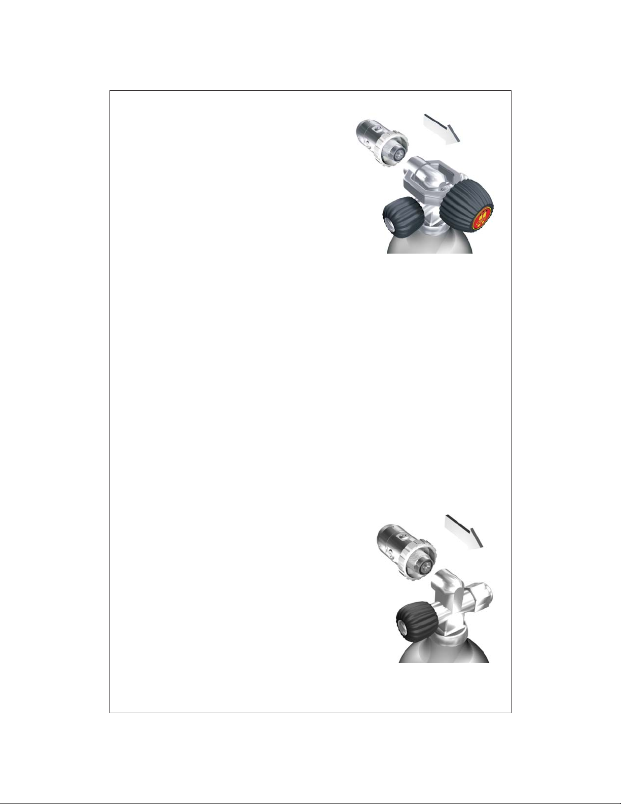
Mounting the First-Stage onto the Cylinder
Valve with the Yoke Adapter (R-239)
Mounting the DIN First-Stage
in the Cylinder Valve
1. With the air outlet opening of the valve facing away
from you, release a small amount of air from the
cylinder by turning the valve hand wheel
counterclockwise to open the valve only slightly.
When air is heard exiting the valve, immediately turn
the valve hand wheel clockwise to close the valve.
This will clear out any water or debris that may be
inside the cylinder valve outlet opening.
2. Remove the dust cover from the R-239 adapter.
Next take the R-239vadapter and screw it on the DIN
threads of the first stage by turning clockwise.
3. Place the first-stage Workhorse Regulator yoke over the cylinder valve so that the inlet
fitting of the Workhorse Regulator aligns with the O-ring of the cylinder valve (be sure to
inspect the O-Ring for cracks etc.). While holding the first stage in place against the valve
O-ring, turn the Black yoke screw Knob clockwise to tighten. Ensure that the yoke screw
mates properly into the small dimple on the backside of the cylinder valve, and tighten the
yoke screw finger tight only.
4. If a submersible pressure gauge is attached to the first-stage, ensure that the gauge is
facing away from you and others. Pressurize the Workhorse Regulator by slowly turning
the cylinder valve hand wheel counterclockwise. Continue to turn the valve hand wheel
counter clockwise until it is fully open.
5. Inspect the first-stage Workhorse Regulator for leaks at just under the surface of the
water or with a soap solution. If leakage is detected, immerse the first-stage and cylinder
valve in water while pressurized to determine the source.
6. If leakage has been detected, follow the procedures for removing the Workhorse
Regulator from the cylinder valve on page 5. If air was leaking between the first-stage
Workhorse Regulator and the cylinder valve, replace or re-seat the cylinder valve O-ring
and repeat the above procedure. If leakage persists, return the cylinder and Workhorse
Regulator to an authorized OMS LLC Dealer for inspection and repair.
1. With the air outlet opening of the valve facing away
from you, release a small amount of air from the cylinder
by turning the valve hand wheel counterclockwise to
open the valve only slightly. When air is heard exiting the
valve, immediately turn the valve hand wheel clockwise
to close the valve. This will clear out any water or debris
that may be inside the threaded cylinder valve outlet
opening.
2. Remove the protective cap from the first-stage
Workhorse Regulator threaded DIN connector.
3. Position the first-stage near the cylinder valve so that
the LP hose of the primary second-stage Workhorse Regulator
2
R-239 Yoke Adapter
(Optional)

Will be configured properly (possibly over the right shoulder). Rotate the first-stage
Workhorse DIN connector into the cylinder valve by turning the hand wheel clockwise by
hand until it is lightly snug. Never use tools to tighten hand wheel.
4. If a submersible pressure gauge is attached to the first-stage, ensure that the gauge is
facing away from you and others. Pressurize the Workhorse Regulator by slowly turning
the cylinder valve hand wheel counterclockwise. Continue to turn the valve hand wheel
counterclockwise until it is fully open.
5. Listen near the first-stage Workhorse Regulator to check for leaks. If leakage is
detected, immerse the first-stage and cylinder valve in water while pressurized to
determine the source.
6. If leakage has been detected, follow the procedures for removing the Workhorse
Regulator from the cylinder valve on page 5. If air was leaking between the first-stage
Workhorse Regulator and the cylinder valve, replace or re-seat the Workhorse Regulator
DIN connector O-ring and repeat the above procedure. If leakage persists, return the
cylinder and Workhorse Regulator to an Authorized OMS LLC Dealer for inspection and repair.
Before each use, the OMS Workhorse Regulator must be given a thorough visual
inspection and functional test. NEVER dive with a Workhorse Regulator that shows signs
of damage, or provides substandard performance until it has received complete
inspection and service from an Authorized OMS LLC Dealer or
OMS .
1. Carefully inspect all hoses fittings to ensure that they are securely connected into their
respective ports on the first-stage Workhorse Regulator. Inspect the hoses themselves to
ensure that the hoses are not worn, blistered, cut, or otherwise damaged. If hose
protectors are present, slide the protector's back to expose the hose fittings, and inspect
the hoses as described above.
2. Visually inspect both the first and second-stage OMS Workhorse Regulator parts for
any signs of external damage, such as bending or cracks.
3. Remove the Protection cap and closely inspect the condition of the first-stage filter. The
filter should appear clean and free of any corrosion or discoloration. If a green residue is
visible on the surface of the filter, moisture has entered the first-stage Workhorse
Regulator and may have caused corrosion to begin forming inside the Workhorse
Regulator. This can seriously impair the Workhorse Regulator performance. White/gray
powder may indicate that the Workhorse Regulator has been used with an aluminum
cylinder that has internal corrosion. Red (rust) indicates a steel cylinder with internal
corrosion. In the event corrosion is found, the Workhorse Regulator (and cylinder) must be
serviced.
If discoloration or contamination residue is found on the surface of the filter, it
is strongly recommended that you DO NOT attempt to dive with the Workhorse Regulator
until it has been serviced from by an Authorized OMS LLC
Dealer or OMS .
4. Connect the first-stage Workhorse Regulator to a fully charged SCUBA cylinder. For
mounting instructions, read the Preparation and Setup section of this manual on pages 2
and 3.
Pre-Dive Checkout
Inspection Checklist:
CAUTION:
®
®
®
®
3

5. SLOWLY open the cylinder valve to pressurize the OMS Workhorse Regulator.
Depress the purge button several times to ensure that there is sufficient airflow. This will
also clear any Protection or debris, from the second stage.
6. Release the purge button and listen to the second-stage OMS Workhorse Regulator
for any airflow. Ensure that the second-stage does not continue to flow once the purge
button is released. If gas does continue to flow after several attempts do not dive the
regulator until it is service by OMS or an authorized OMS service center
7. Place the second-stage Workhorse Regulator mouthpiece in your mouth, and inhale
slowly and deeply several times. The Workhorse Regulator should deliver enough air for
you to breathe easily without noticeable resistance.
8. Go ahead start to explore.
Whenever your cylinder is filled, request verification that the water vapor content of the
supplied gas is less than -65F dew point. Most dive stores and operators obtain testing
and certification to provide evidence of compliance with pure gas standards. Excessive
water vapor can increase the potential for Workhorse Regulator freeze-up and subsequent
regulator failure.
Gas with excessive water vapor can cause the OMS Workhorse regulator
to freeze up and result in regulator failure.
1. Shut your gas off by turning the Valve Handwheel(s) clockwise until they stop.
2. Push the purge cover of the Workhorse Regulator second-stage until the gas stops
flowing and your submersible pressure gauge reads “0” psi.
3. Rotate counterclockwise the first-stage DIN hand wheel to loosen and remove the Deco
Regulator First Stage from the cylinder valve(s).
4. Install the protector cap (Dry it if necessary) over the threads of the Deco First Stage.
®
®
®®
®
Anti Freeze Protection
WARNING:
Post Dive Care and Maintenance
Removal of the Workhorse Regulator from the Cylinder Valve (DIN
Connector)
4

USING ENRICHED AIR NITROX (EAN)
WARNING:
Regulator Owner's Manual
NOTE: OVERVIEW OF FEATURES
Second Stage Hose Configuration
This section of your owner's manual contains important information
regarding the use of your equipment with enriched air (EAN/Nitrox). Do not attempt to use
this product with enriched air until you have read and understand this section of the
manual. To do otherwise increases your risk of injury or death.
Obtain an EAN (Nitrox) Certification. In order to enjoy the special benefits that EAN/Nitrox
can provide, it is extremely important to obtain special training from a nationally
recognized training agency in addition to that which is provided for open water scuba.
Your OMS regulator has been prepared for use with Enriched Air Nitrox (EAN) where
the percentage of oxygen in the EAN does not exceed 40%. This is possible because
each regulator is built to a high standard of cleanliness using EAN compatible components
and lubricants. In addition, each regulator design has passed stringent adiabatic
compression testing to ensure its safety and compatibility with increased percentages
of oxygen. If it is your intention to use your new OMS regulator with EAN (02 not to
exceed 40%), it is imperative that you maintain the internal cleanliness of the regulator
(see section on Care and Maintenance). If it is your intent to use the regulator
interchangeably with breathing air, the breathing air should be oxygen-compatible and the
hydrocarbons do not exceed 0.1 mg/m3. Your local authorized OMS dealer can help you
determine whether the breathing air that they provide meets this criteria.
Standard compressed breathing air, often referred to as Grade E in the United States,
does not necessarily meet this criteria. Grade E breathing air may contain a certain
level of hydrocarbons, including traces of compressor oil that while not considered
harmful to breathe, can pose a risk in the presence of elevated oxygen content.
Passing hydrocarbons through a valve and regulator creates a cumulative effect where
the hydrocarbons build up over time along the internal passageways of the equipment.
When these hydrocarbons come in contact with high-pressure oxygen enriched air, they
can pose a very real hazard that can lead to combustion.
Therefore, if a regulator has had use with Grade E breathing air, it should be returned
to an authorized OMS dealer for overhaul service including hydrocarbon cleaning,
prior to being put back into Nitrox service. Although second stage components are not
exposed to high pressure EAN, OMS recommends that the same cleaning procedures be
followed for the complete regulator. This prevents the possibility of cross contamination
and guarantees the cleanliness of the entire regulator.
OMS offers additional models of regulators that are designed and manufactured
for use with Enriched Air Nitrox where the percentage of oxygen does not exceed
40%. For information about these models, consult your authorized OMS dealer.
®
®
®
®
®
®
®
5

Removal of the Workhorse Regulator from the Cylinder Valve when using
the optional Yoke Adapter (R-239)
Required Maintenance
NOTE:
1. Shut your gas off by turning the Valve Handwheel(s) clockwise until they stop.
2. Push the purge cover of the Workhorse Regulator second-stage until the gas stops
flowing and your submersible pressure gauge reads “0” psi.
3. Turn the Black Knob on the Yoke Adapter (R-239) counterclockwise and remove the
Workhorse Regulator first stage from the cylinder valve.
4. Dry the Protection cover and install it over the inlet opening of the first stage by
tightening the Yoke Adapter knob.
Lack of maintenance, improper cleaning and/or prolonged or improper storage
can cause internal corrosion and/or deterioration of O-ring seals, filter and seating
surfaces. This type of abuse will void your OMS warranty.
1. When the Workhorse Regulator is removed from the SCUBA cylinder valve, it is
important that the Protection Cover is installed in the R-239 Yoke Adapter inlet or over the
threaded DIN connector. This is necessary to prevent damage to the threads of the DIN
Connector, or entrance of water and debris into the first-stage. This protector must be
completely dry before securing it in the inlet fitting of the R-239 Adapter or over the
threaded DIN connector or damage to the regulator may result.
2. Always soak your First and Second Stage thoroughly with a solution of OMS Corrostop
(this will remove destructive salt and mineral deposits) or clean fresh water while the
regulator is attached to the cylinder(s) and pressurized with air. Do not clean your
regulator if it is not pressurized as water may enter the internal parts of the regulator and
cause damage. Be sure to actively move the Second stage through the solution to
dislodge debris and remove all salt water.
3. If soaking the Workhorse Regulator while it is pressurized is not possible, it may be
briefly soaked unpressurized. Be sure the Protection cap or DIN protector cap is secure
over the first-stage inlet or threaded DIN connector. DO NOT depress the purge button or
turn the adjustment knob while Workhorse Regulator is submerged. Failure to do this will
allow water to enter the internal parts of the second stage causing damage.
4. After soaking the Workhorse Regulator in a solution of Correstop or water, remove it
and the cylinder(s) from the bath. While the valve(s) is still open position, depress the
second stage purge cover several times to remove the residual water.
5. Next, depressurize the Workhorse Regulator by first turning the cylinder valve hand
wheel(s) clockwise until they stop. Then depress the purge cover of the second stage until
the gas stops flowing and your SPG reads 0 PSI”. Remove the first stage from the
cylinder valve(s) (see Removal of Workhorse Regulator from Cylinder Valve Section of this
Manual for details).
5. Dry by laying the regulator on an adsorbent lint free surface or securely hang by the first
stage.
6. When the Workhorse Regulator is completely dry, store it laying flat in a clean
equipment bag
®
®
6

OMS LLC
P.O. Box 146 Montgomery, NY 12549
Tel: 845.457.1501 Fax: 845.457.1504 www.omsdive.com
.
..
© OMS LLC
This manual suits for next models
1
Table of contents
Other OMS Diving Instrument manuals