ON Semiconductor EZAIRO 7160 SL User manual

©Semiconductor Components Industries, LLC, 2018
December, 2018 −Rev. 0
1Publication Order Number:
E7160/D
EZAIRO 7160 SL HYBRID
Wireless-Enabled Audio
Processor for Hearing Aids
Introduction
Ezairo®7160 SL is an open−programmable DSP−based hybrid
specifically designed for wireless, high−performance hearing aids.
The Ezairo 7160 SL hybrid is based on the Ezairo 7100
System−on−Chip (SoC) and includes RSL10−the industry’s lowest
power Bluetooth®5 radio SoC, EA2M a 2 Mb EEPROM, and all
necessary passive components for interfacing with transducers.
Ezairo 7100 features a high precision quad−core architecture that
delivers 375 MIPS without sacrificing power consumption. The
dual−Harvard CFX Digital Signal Processor (DSP) core is optimized
to run advanced hearing aid algorithms, while the HEAR Configurable
Accelerator engine performs many different types of audio processing.
Complementing the DSP core, the Arm®Cortex®−M3 processor
supports wireless protocols and combines an open−programmable
controller with hardware accelerators for audio coding and error
correction support. Ezairo 7100 also includes a programmable Filter
Engine that enables time domain filtering and supports an
ultra−low−delay audio path.
Offering the industry’s lowest power consumption in deep sleep and
peak receiving, RSL10 is a highly flexible multi−protocol 2.4 GHz
radio specifically designed for use in high−performance wearable and
medical applications. With its Arm Cortex−M3 processor and
LPDSP32 DSP core, RSL10 supports Bluetooth low energy
technology and 2.4 GHz proprietary protocols.
Development Tools
Ezairo Preconfigured Suite (Pre Suite)*
The Ezairo Pre Suite provides a complete framework to easily
develop Ezairo−based hearing aids and fitting software. Included in
the Ezairo Pre Suite is a pre−loaded firmware bundle, configuration
software, and a cross−platform Software Development Kit (SDK) to
develop your own fitting software.
RSL10 Development Tools
The RSL10 development tools provide an Eclipse−based SDK
complete with Bluetooth profiles and wireless audio codecs for the
RSL10’s Arm Cortex−M3 processor. The RSL10’s LPDSP32 code
can be developed using the Synopsys development tools which are
available by request.
Open−Programmable Evaluation and Development Kit (EDK)
To develop your own firmware on Ezairo 7160 SL, the Ezairo 7100
Evaluation and Development Kit (EDK) includes optimized hardware,
programming interface, and a comprehensive Integrated Development
Environment (IDE).
*This datasheet describes all features of the Ezairo 7160 SL hybrid module. Not
all of these features are available using the Ezairo Preconfigured Suite.
www.onsemi.com
MARKING DIAGRAM
SIP57
CASE 127EX
Device Package Shipping†
ORDERING INFORMATION
E7160−0−102A57−AG
(RoHS Compliant)
SIP57
(Pb−Free)
250 / Tape &
Reel
†For information on tape and reel specifications,
including part orientation and tape sizes, please
refer to our Tape and Reel Packaging Specification
Brochure, BRD8011/D.
(Top View)
E7160−0
XXXXXX
E7160−0 = Specific Device Code
XXXXXX = Work Order Number

EZAIRO 7160 SL HYBRID
www.onsemi.com
2
Key Features
•Programmable Flexibility: The open−programmable
DSP−based system can be customized to the specific
signal processing needs of manufacturers. Algorithms
and features can be modified or completely new
concepts implemented without having to modify the
chip.
•Fully Integrated Hybrid: Includes the Ezairo 7100
SoC, RSL10 radio SoC, 2 Mb of EEPROM memory,
and the necessary passive components to directly
interface with the transducers required in a hearing aid.
•Fitting Support: Support for Microcard, HI−PRO 2,
HI−PRO USB, QuickCom, and NOAHlinkt, including
NOAHlink’s audio streaming feature.
•These devices are Pb−Free, Halogen Free/BFR Free
and are RoHS Compliant
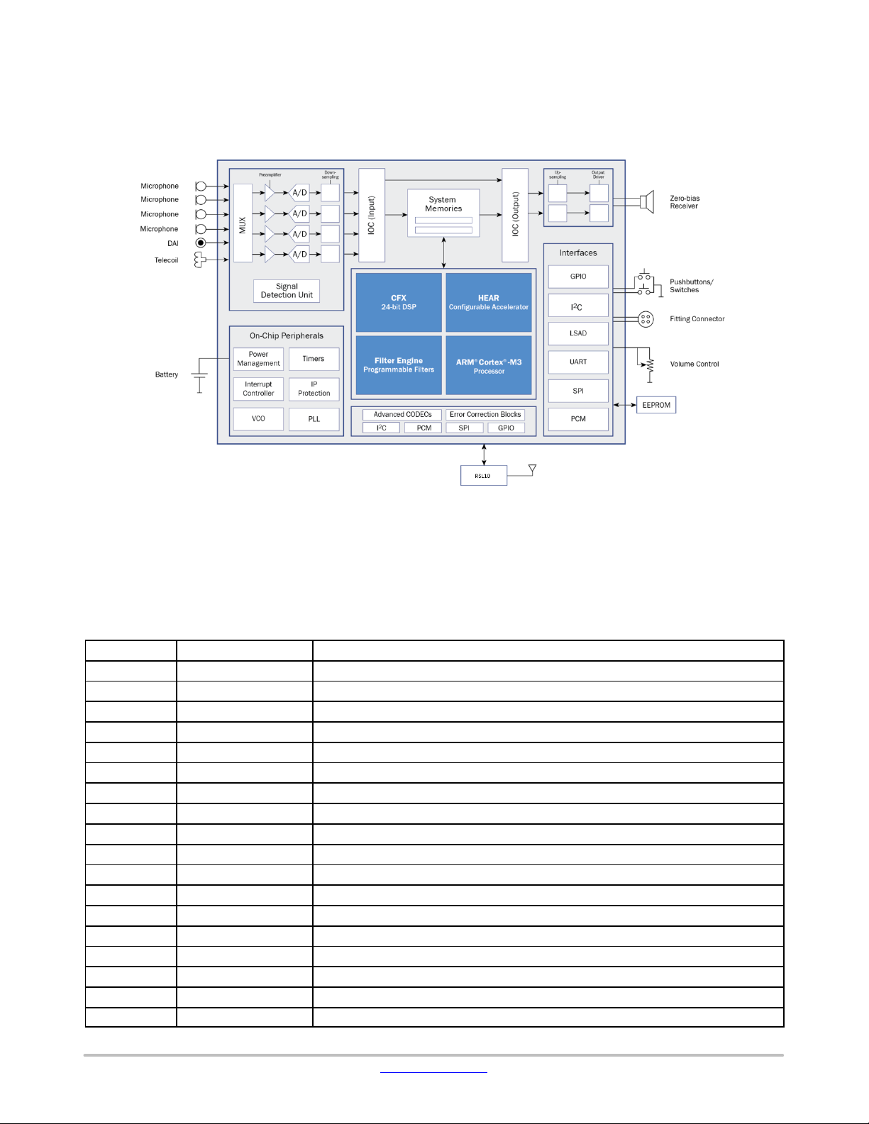
Ezairo 7100 DSP Main Features:
•Quad−core Architecture: Includes a CFX DSP, a
HEAR Configurable Accelerator, an Arm Cortex−M3
Processor Subsystem and a programmable Filter
Engine. The system also includes an efficient
input/output controller (IOC), system memories, input
and output stages along with a full complement of
peripherals and interfaces.
•CFX DSP: A highly cycle−efficient, programmable
core that uses a 24−bit fixed−point, dual−MAC,
dual−Harvard architecture.
•HEAR Configurable Accelerator: An optimized
signal processing engine designed to perform common
signal processing operations and complex standard
filterbanks.
•Arm Cortex−M3 Processor Subsystem: A complete
subsystem that supports efficient data transfer to and
from the wireless transceiver or multiple transceivers.
•Programmable Filter Engine: A filtering system that
allows applying a various range of pre−or post−
processing filtering, such as IIR, FIR and biquad filters.
•Configurable System Clock Speeds: 1.28 MHz,
1.92 MHz, 2.56 MHz, 3.84 MHz, 5.12 MHz, 6.4 MHz,
7.68 MHz, 8.96 MHz, 9.60 MHz, 10.24 MHz (default
clock calibration), 12.80 MHz and 15.36 MHz to
optimize the computing performance versus power
consumption ratio. The calibration entries for these 12
clock speeds are stored in the manufacturing area of the
EEPROM.
•Ultra−high Fidelity: 85 dB system dynamic range with
up to 110 dB input signal dynamic range,
exceptionally−low system noise and low group delay.
•Ultra−low Power Consumption: <0.7 mA @
10.24 MHz system clock (executing a tight MAC−loop
in the CFX DSP core plus a typical hearing aid
filterbank on the HEAR Configurable Accelerator).
•Data Security: Sensitive program data can be
encrypted for storage in EEPROM to prevent
unauthorized parties from gaining access to proprietary
algorithm intellectual property.
•High Speed Communication Interface: Fast
I2C−based interface for quick download, debugging and
general communication.
•Highly Configurable Interfaces: Two PCM interfaces,
two I2C interfaces, two SPI interfaces, a UART
interface as well as multiple GPIOs can be used to
stream configuration, control or signal data into and out
of the Ezairo 7160 SL hybrid.
RSL10 Main Features:
•Arm Cortex−M3 Processor: A 32−bit core for
real−time applications, specifically developed to enable
high−performance low−cost platforms for a broad range
of low−power applications.
•LPDSP32: A 32−bit Dual Harvard DSP core that
efficiently supports audio codecs required for wireless
audio communication. Various codecs are available to
customers through libraries that are included in
RSL10’s development tools.
•Radio Frequency Front−End: Based on a 2.4 GHz RF
transceiver, the RFFE implements the physical layer of
the Bluetooth low energy technology standard and other
proprietary or custom protocols.
•Protocol Baseband Hardware: Bluetooth 5 certified
and includes support for a 2 Mbps RF link and custom
protocol options. The RSL10 baseband stack is
supplemented by support structures that enable
implementation of ON Semiconductor and customer
designed custom protocols.

EZAIRO 7160 SL HYBRID
www.onsemi.com
3
Table 1. ABSOLUTE MAXIMUM RATINGS
Symbol Parameter Min Max Unit
VBAT Power supply voltage 2 V
RCVRBAT Output drivers power supply voltage 2 V
VDDO2I/O supply voltage 3.3 (Note 1) V
Vin Voltage at any input pin GNDC−0.3 VDDO + 0.3 V
DGND, AGND, HGND Digital and Analog Grounds 0−V
T functional Functional temperature range (Note 2) −40 85 °C
T operational Operational temperature range (Note 2) 0 50 °C
T storage Storage temperature range −40 85 °C
Caution: Class 2 ESD Sensitivity, JESD22−A114−B (2000 V)
Stresses exceeding those listed in the Maximum Ratings table may damage the device. If any of these limits are exceeded, device functionality
should not be assumed, damage may occur and reliability may be affected.
1. In some applications, VDDO can be higher than 2.1 V (maximum 3.3 V). In such cases, the user must set the VDDM voltage at a minimum
of 1.1 V
2. Electrical Specification may exceed listed tolerances when out of the temperature range 0 to 50°C
Electrical Performance Specifications
The tests were performed at 20°C with a 1.25 V supply voltage and 4.7 Wseries resistor to simulate a nominal hearing aid
battery. The system clock (SYS_CLK) was set to 5.12 MHz and an audio input sampling frequency of 16 kHz was used.
Parameters marked as screened are tested on each chip.
Table 2. ELECTRICAL SPECIFICATIONS
Description Symbol Conditions Min Typ Max Units Screened
OVERALL
Supply Voltage VBAT Supply voltage measured
at the VBAT pin
1.18
(Note
3, 4)
1.25 2.0 V
I/O Supply Voltage
Domain 2
VDDO21.05 −3.3 V
Current consumption IVBAT Filterbank: 30% load CFX:
100% load SYS_CLK:
10.24 MHz, No activity on
the RSL10
−700 −mA
Ezairo Pre Suite firmware
bundle running at15.36 MHz,
all algorithms active, no
transducers connected, no
activity on the RSL10.
−TBD −mA
Stand by current Istb Using ON Semiconductor’s
macro
40 120 mA
3. In order to be able to use a VBAT Min of 1.1 V, the following reduced operating conditions for the RSL10 should be observed:
−Maximum Tx power 0 dBm.
−SYSCLK ≤24 MHz.
−Functional temperature range limited to 0 −50°C
The following trimming parameters should be used:
−VCC = 1.10 V
−VDDC = 0.92 V
−VDDM = 1.05 V, will be limited by VCC at end of battery life
−VDDRF = 1.05 V, will be limited by VCC at end of battery life. VDDPA should be disabled
RSL10 should enter in end−of−battery−life operating mode if VCC falls below 1.03 V. VCC will remain above 1.03 V if VBAT ≥1.10 V under
the restricted operating conditions described above.
4. Min VBAT = 1.05 V if RSL10 is disabled

EZAIRO 7160 SL HYBRID
www.onsemi.com
4
Table 2. ELECTRICAL SPECIFICATIONS
Description ScreenedUnitsMaxTypMinConditionsSymbol
VREG
Regulated voltage output VREG Iload = 100 mA0.96 0.97 0.98 V n
Regulator PSRR VREGPSRR 1 kHz, VBAT = 1.25 V 76 80 −dB
Load current ILOAD − − 2 mA
Load regulation LOADREG 5 mA < Iload < 2 mA −4 10 mV/mA
Line regulation LINEREG Iload = 1 mA −2 5 mV/V
VDDA
Output voltage trimming
range
VDDA Control register configured,
typical values
1.8 2.0 2.1 V n
Regulator PSRR VDDAPSRR 1 kHz, VBAT = 1.25 V 40 50 −dB
Load current ILOAD − − 1 mA
Load regulation LOADREG VBAT = 1.2 V; 100 mA <
Iload < 1 mA
−4 10 mV/mA
Line regulation LINEREG 1.2 V < VBAT < 1.86 V;
Iload = 100 mA
−6 20 mV/V
VDBL
Output voltage trimming
range
VDBL Control register configured,
typical values, unloaded
1.6 2.0 2.2 V n
Regulator PSRR VDBLPSRR 1 kHz, VBAT=1.25 V 30 40 −dB
Load current ILOAD ITRIM (A_CP_VDBL_CTRL)
= 0x7
− − 15 mA
Load regulation LOADREG VBAT = 1.2 V; 100 mA <
Iload < 3 mA
−4 10 mV/mA
Line regulation LINEREG VBAT > 1.2 V; Iload = 100 mA−6 20 mV/V
VDDC
Digital supply output volt-
age trimming range
VDDC Control register configured,
typical values, unloaded
0.72 −
(Note 5)
1.32 V n
VDDC output level adjust-
ment
VDDCSTEP 1.5 2.5 3 mV n
Regulator PSRR VDDCPSRR 1 kHz, VBAT = 1.25 V 25 30 −dB
Load current ILOAD Delivered by LDO − − 5 mA
Load regulation LOADREG −5 10 mV/mA
Line regulation LINEREG −6 12 mV/V
VDDM
Memory supply output volt-
age trimming range
VDDM Control register configured,
typical values, unloaded
0.82 −
(Note 6)
1.32 V n
VDDM output level adjust-
ment
VDDMSTEP 1.5 2.5 3 mV n
Regulator PSRR VDDMPSRR 1 kHz, VBAT = 1.25 V 25 30 −dB
Load current ILOAD Delivered by LDO − − 5 mA
Load regulation LOADREG −5 10 mV/mA
Line regulation LINEREG −6 12 mV/V
POWER−ON−RESET (triggered from the RSL10 value)
POR voltage VBATPOR − − 1.0 V
INPUT STAGE
Analog input voltage range VIN 0−2 V
Preamplifier gain PAG 3 dB steps 0−36 dB n
Preamplifier gain accuracy PAG acc 1 kHz, PAG from 0 to 36 dB −1.5 0 1.5 dB n

EZAIRO 7160 SL HYBRID
www.onsemi.com
5
Table 2. ELECTRICAL SPECIFICATIONS
Description ScreenedUnitsMaxTypMinConditionsSymbol
INPUT STAGE
Input impedance RIN Non−0dB preamplifier gains 370 500 725 kWn
Input referred noise INIRN AIR connected to AGND
Unweighted, 100 Hz to
10 kHz BW
Preamplifier settings:
mVrms
0 dB −53 −
12 dB −13 −
15 dB −9−
18 dB −6.6 10.6 n
21 dB −4.9 −
24 dB −4.3 −
27 dB −3.7 −
30 dB −3.2 −
33 dB −3.2 −
36 dB −3.2 −
Input Dynamic Range
(Note 7)
INDR AIR connected to AGND
Unweighted, 100 Hz to
10 kHz BW
Preamplifier settings:
dB
0 dB −86 −
12 dB −86 −
15 dB −86 −
18 dB 81 86 −n
21 dB −85 −
24 dB −82 −
27 dB −82 −
30 dB −80 −
33 dB −77 −
36 dB −74 −
Input peak THD+N INTHD+N Gain between 0 and 30 dB,
−10 dBFS signal, 1 kHz
− − −68 dB n
Input peak THD+N INTHD+N Gain between 33 and 36 dB,
−10 dBFS signal, 1 kHz.
− − −66 dB
OUTPUT DRIVER
Maximum peak current IDO High Power mode − − 25 mA
Output impedance RDO Normal mode, Iload = 1 mA −4.5 5.5 W
Output impedance RDO High Power mode −2.5 4 W
Output dynamic range DODR Normal mode, VBAT = 1.25 V 90 − − dB
Output THD+N DOTHDN At 1 kHz, −6 dBFS, 8 kHz
bandwidth, VBAT = 1.25 V,
normal mode
− −78 −76 dB
10−BIT LOW−SPEED A/D
Input voltage range LSADRANGE Peak input voltage 0−1.94 V n
INL LSADINL From GND to 2*VREG −4−+4 LSB
DNL LSADDNL From GND to 2*VREG −2−+2 LSB
Sampling frequency LSADSF All channels sequentially −12.8 −kHz
Channel sampling frequency LSADCH_SF −1.6 −kHz

EZAIRO 7160 SL HYBRID
www.onsemi.com
6
Table 2. ELECTRICAL SPECIFICATIONS
Description ScreenedUnitsMaxTypMinConditionsSymbol
SIGNAL DETECTION UNIT
Preamplifier gain SDUPAG 3 dB steps 0−36 dB n
Equivalent IRN SDUIRN Non−weighted, 30 dB gain,
100 Hz −10 kHz
− − 20 mVrms n
Input impedance SDUR370 500 725 kOhm n
Low Pass Filter Bandwidth SDULPF −50 −kHz
ADC input signal range SDURANGE Referred to VREG −1−+1 V
ADC resolution SDURES 12 −bits
ADC sampling frequency SDUSF At slow_clock = 1.28 MHz 1−64 kHz
DIGITAL
Voltage level for high input VIH VDDO
*0.8
− − Vn
Voltage level for low input VIL − − VDDO*0.2 V n
Voltage level for high output VOH 2 mA source current VDDO
*0.8
−Vn
Voltage level for low output VOL 2 mA sink current − − VDDO*0.2 V n
Oscillator frequency trim-
ming precision
SYS_CLK −1−+1 % n
Oscillator frequency stabili-
ty over temperature
SYS_CLK Over temperature range of
0 to 50°C
−1.5 −+1.5 %
Recommended working
frequency
SYS_CLK For recommended VDDC
and VDDM
1.28 −15.36 MHz
Oscillator period jitter RMS at System clock:
1.28 MHz, before
multiplication
− − 400 ps
PLL lock time For an input phase error
<2%, input reference clock
of 128 kHz, output clock of
2.56 MHz
− − 10 ms n
PLL tracking range −2−2 %
LOW DELAY PATH
Group Delay Using the low delay path of
the Filter Engine
−44 −ms
Product parametric performance is indicated in the Electrical Characteristics for the listed test conditions, unless otherwise noted. Product
performance may not be indicated by the Electrical Characteristics if operated under different conditions.
5. Recommended VDDC values depend on the system clock (SYS_CLK) frequency. Table 3 gives the recommended VDDC values for different
system clocks.
6. The minimum VDDM value required for proper system functioning is 0.90 V
7. The audio performance might be slightly impacted when the RSL10 radio is turned on. Degradation depends on the duty cycle of the
communication, on the external components.

EZAIRO 7160 SL HYBRID
www.onsemi.com
7
Table 3. RECOMMENDED MINIMUM VDDC LEVEL
Operating Frequency (MHz) Minimum VDDC Voltage (V)
1.28 to 5.12 0.73
5.13 to 10.24 0.82 (Note 8)
10.25 to 12.8 0.85
12.81 to 15.36 0.88 (Note 9)
8. The default VDDC calibration entry, stored in the manufacturing area of the EEPROM at address 0x0064, should be used for operation at 0.82 V.
9. An alternate VDDC calibration entry, stored in the manufacturing area of the EEPROM at address 0x00E8, should be used for operation at 0.88 V.
Table 4. EA2M ELECTRICAL SPECIFICATIONS
EEPROM burn cycles 1,000,000 − − Cycles
Current consumption – writ-
ing to EEPROM
IW−0.7 −mA
Current consumption – read
from EEPROM
IR−0.4 −mA
*The electrical specifications of the EA2M EEPROM can be found in the EA2M datasheet.
Table 5. RSL10 ELECTRICAL SPECIFICATIONS
Current consumption RX IVBAT Rx Mode, ON Semiconductor proprietary
audio streaming protocol at 7 kHz audio
BW, 37 ms delay.
−1.15 −mA
Standby Mode current Istb Digital blocks and memories are not clocked
and are powered at a reduced voltage.
−30 −mA
Peak Current consumption
at 1 Mbps
IBATRFRX VDDRF =1.1 V, 100% duty cycle −5.6 −mA
Rx Sensitivity, 1 Mbps, BLE 0.1% BER, Single−ended on chip antenna
match to 50 W
− −94 −dBm
Tx peak power consumption
at VBAT = 1.25 V (Note 10)
IBATRFTX Tx power 0 dBm, VDDRF = 1.07 V,
VDDPA: off, LDO mode
−8.9 −mA
*The electrical specifications of the RSL10 radio SoC can be found in the RSL10 datasheet.
10.Ezairo 7160 SL will not pass regulatory certification for TX power > 1 dBm
Packaging and Manufacturing
•Ultra−Miniature: Suitable for all hearing aid styles
including CIC, ITE, RITE, BTE, and mini−BTE.
•Reflowable: Ezairo 7160 SL is re−flowable onto FR4
and other substrates.
•RoHS Compliant: Ezairo 7160 SL complies with the
RoHS directive.

EZAIRO 7160 SL HYBRID
www.onsemi.com
8
System Diagram
Figure 1 is a simplified diagram of the hybrid system that shows the major internal functional blocks and possible external
peripherals.
Figure 1. Ezairo 7160 SL Hybrid System Diagram
Ezairo 7160 SL Hybrid Interface Specifications
A total of 57 pads are present on the Ezairo 7160 SL hybrid. These pads are the interfaces between the hybrid and the other
components in the hearing aid. They are listed in Table 6 along with the internal connections.
Table 6. PAD DESCRIPTION
Ball Number Hybrid Pad Name Hybrid Pad Description
A1 VSSRF RF analog ground
A2 VSSRF RF analog ground
A3 VSSRF RF analog ground
A4 VBAT Power Supply
A5 DGND Digital ground for the Ezairo 7100
A6 NRESET Reset pin for the Ezairo 7100
A7 DIO21 Digital Input Output 21 for the Ezairo 7100
A8 SCL Debug Port Clock for the Ezairo 7100
A9 SDA Debug Port Data for the Ezairo 7100
A10 RCVRBAT Output Stage Power Supply for the Ezairo 7100
B1 VSSRF RF analog ground
B2 VSSRF RF analog ground
B3 RFIO12 Digital Input Output 12 for the RSL10
B4 VDDO2 IO Power Supply for DIO20 to DIO29 of Ezairo 7100 and for all DIO of the RSL10
B5 DIO9 Digital Input Output 9 for the Ezairo 7100
B6 DIO6 Digital Input Output 6 for the Ezairo 7100
B7 DIO20 Digital Input Output 20 for the Ezairo 7100
B8 RCVR1N Receiver Output 1 Negative for the Ezairo 7100

EZAIRO 7160 SL HYBRID
www.onsemi.com
9
Table 6. PAD DESCRIPTION
Ball Number Hybrid Pad DescriptionHybrid Pad Name
B9 RCVR0N Receiver Output 0 Negative for the Ezairo 7100
B10 HGND Output Driver Ground for the Ezairo 7100
C1 RF RF signal input/output (Antenna)
C3 JTCK CM3−JTAG Test Clock for the RSL10
C4 VDBL Regulated doubled voltage output for Ezairo 7100
C5 DIO8 Digital Input Output 8 for the Ezairo 7100
C6 DIO5 Digital Input Output 5 for the Ezairo 7100
C7 DIO22 Digital Input Output 22 for the Ezairo 7100
C8 RCVR1P Receiver Output 1 Positive for the Ezairo 7100
C9 RCVR0P Receiver Output 0 Positive for the Ezairo 7100
C10 DIO29 Digital Input Output 29 for the Ezairo 7100
D1 VSSA Analog ground for the RSL10
D4 JTMS CM3−JTAG Test Mode State for the RSL10
D5 RFNRESET Reset pin for the RSL10
D6 DIO4 Digital Input Output 4 for the Ezairo 7100
D7 DIO7 Digital Input Output 7 for the Ezairo 7100
D8 EXTCLK EXT_CLK pin for the Ezairo 7100
D9 DIO23 Digital Input Output 23 for the Ezairo 7100
D10 DIO24 Digital Input Output 24 for the Ezairo 7100
E1 XTAL32KN Xtal input pin for 32 kHz xtal
E2 RES RESERVED
E3 RFGND RF Ground for RSL10
E4 AOUT Analog test pin
E5 RFIO0 Digital Input Output 0 for the RSL10
E6 RFIO1 Digital Input Output 1 for the RSL10
E7 GND_MIC Input Transducer Ground for the Ezairo 7100
E8 VMIC Regulated voltage for microphone for the Ezairo 7100
E9 AI3 Analog Input 3: Direct Analog Input for the Ezairo 7100
E10 AGND Analog Ground for the Ezairo 7100
F1 XTAL32KP Xtal output pin for 32 kHz xtal
F2 VDCRF DC−DC output voltage to external LC filter for RSL10
F3 RFGND RF Ground for RSL10
F4 RFIO2 Digital Input Output 2 for the RSL10
F5 VCCRF DC−DC filtered output for the RSL10
F6 RFIO3 Digital Input Output 3 for the RSL10
F7 AI0 Analog Input 0: Microphone or Telecoil Input for the Ezairo 7100
F8 AI1 Analog Input 1: Microphone or Telecoil Input for the Ezairo 7100
F9 AI2 Analog Input 2: Microphone or Telecoil Input for the Ezairo 7100
F10 VREG Regulated voltage output for the Ezairo 7100

EZAIRO 7160 SL HYBRID
www.onsemi.com
12
Connection Diagram
The following connections should be observed when the Ezairo 7160 SL is used in typical hearing aid applications:
Figure 5. Connection Diagram, Bottom View
Ezairo 7160 SL
F1 F2 F3 F4 F5 F6 F7 F8 F9 F10
E1 E2 E3 E4 E5 E6 E7 E8 E9 E10
D1 D4 D5 D6 D7 D8 D9 D10
C1 C3 C4 C5 C6 C7 C8 C9 C10
B1 B2 B3 B4 B5 B6 B7 B8 B9 B10
A1 A2 A3 A4 A5 A6 A7 A8 A9 A10
VSSRF2 VSSRF3 VSSRF4 VBAT DGND NRESET DIO21 SCL SDA RCVRBAT
VSSRF1 VSSRF5 RFIO12 VDDO2 DIO9 DIO6 DIO20 RCVR1N RCVR0N HGND
RF JTCK VDBL DIO8 DIO5 DIO22 RCVR1P RCVR0P DIO29
VSSA JTMS RFNRESET DIO4 DIO7 EXTCLK DIO23 DIO24
XTAL32KN RESERVED RFGND2 AOUT RFIO0 RFIO1 GND_MIC VMIC Audio In AGND
XTAL32KP VDCRF RFGND1 RFIO2 VCCRF RFIO3 Telecoil Front Mic Rear Mic VREG
Receiver
Battery
Programming Strip
Volume/Memory +
Volume/Memory −
TP
TP
Front Microphone
Rear Microphone
Telecoil
TP
TP
TP
TP
TP
Direct Audio Input
Telecoil Reed Switch
ARD1
ARD0
Optional Receiver Detection Connections
Ezairo 7160 SL Pre Suite Connection Diagram
w47μF
1.5pF
1.8nH 3nH
1.5pF
L
C
Antenna and matching circuit
TP
XTAL32
(bottom view)
NOTE: −ON Semiconductor recommends to use the 9HT12−32.768KDZF−T SMD crystal from TXC corporation.
−Harmonic filter on RF pin required to pass regulatory emission tests
−For the purposes of BT−SIG certification, the following signals must be accessible or brought out to solderable test points: VBAT,
GND, and either RFIO2 & RFIO3 or DIO24 & DIO29. (Please see AND9838/D for more details)

EZAIRO 7160 SL HYBRID
www.onsemi.com
13
EZAIRO 7100 ARCHITECTURE OVERVIEW
The Ezairo 7100 system is an asymmetric quad−core
architecture, mixed−signal system−on−chip designed
specifically for audio processing. It centers around four
processing cores: the CFX Digital Signal Processor (DSP),
the HEAR Configurable Accelerator, the Arm Cortex−M3
Processor Subsystem, and the Filter Engine.
CFX DSP Core
The CFX DSP core is used to configure the system and the
other cores, and it coordinates the flow of signal data
progressing through the system. The CFX DSP can also be
used for custom signal processing applications that can’t be
handled by the HEAR or the Filter Engine.
The CFX DSP is a user−programmable general−purpose
DSP core that uses a 24−bit fixed−point, dual−MAC,
dual−Harvard architecture. It is able to perform two MACs,
two memory operations and two pointer updates per cycle,
making it well−suited to computationally intensive
algorithms.
The CFX features:
•Dual−MAC 24−bit load−store DSP core
•Four 56−bit accumulators
•Four 24−bit input registers
•Support for hardware loops nested up to four deep
•Combined XY memory space (48 bits wide)
•Dual address generator units
•A wide range of addressing modes:
♦Direct
♦Indirect with post−modification
♦Modulo addressing
♦Bit reverse
For further information on the usage of the CFX DSP,
please refer to the Hardware Reference Manual and to the
CFX DSP Architecture Manual.
HEAR Configurable Accelerator
The HEAR coprocessor is designed to perform both
common signal processing operations and complex standard
filterbanks such as the WOLA filterbank, reducing the load
on the CFX DSP core.
The HEAR Configurable Accelerator is a highly
optimized signal processing engine that is configured
through the CFX. It offers high speed, high flexibility and
high performance, while maintaining low power
consumption. For added computing precision, the HEAR
supports block floating point processing. Configuration of
the HEAR is performed using the HEAR configuration tool
(HCT). For further information on the usage of the HEAR,
please refer to the HEAR Configurable Accelerator
Reference Manual.
The HEAR is optimized for advanced hearing aid
algorithms including but not limited to the following:
•Dynamic range compression
•Directional processing
•Feedback cancellation
•Noise reduction
To execute these and other algorithms efficiently, the HEAR
excels at the following:
•Processing using a weighted overlap add (WOLA)
filterbank
•Time domain filtering
•Subband filtering
•Attack/release filtering
•Vector addition/subtraction/multiplication
•Signal statistics (such as average, variance and
correlation)
Arm Cortex−M3 Processor Subsystem
The Arm Cortex−M3 Processor Subsystem provides
support for data transfer to and from the wireless transceiver.
The subsystem includes hardwired CODECS (G.722,
CVSD), Error Correction support (Reed−Solomon,
Hamming), interfaces (SPI, I2C, PCM, GPIOs), as well as an
open−programmable Arm Cortex−M3 processor.
Arm Cortex−M3 Processor
The Arm Cortex−M3 processor is a low−power processor
that features low gate count, low interrupt latency, and
low−cost debugging. It is intended for deeply embedded
applications that require fast interrupt response features.
GNU tools provide build and link support C programs that
run on the Arm Cortex−M3 processor.
Filter Engine
The Filter Engine is a core that provides low−delay path
and basic filtering capabilities for the Ezairo 7100 system.
The Filter Engine can implement filters (either FIR or IIR)
with a total of up to 160 coefficients. FIR filters are
implemented using a direct−form structure. IIR filters are
implemented with a cascade of second−order sections
(biquads), each implemented as a direct−form I filter.
The Filter Engine is programmable, but does not include
direct debugging access. The CFX can monitor the Filter
Engine state through control and configuration registers on
the program memory bus.
Ezairo 7160 SL IOs
Digital Input/Output (DIO) Pads
A total of 12 DIOs of the Ezairo 7100 are available on the
Ezairo 7160 SL hybrid. These pads can all be configured for
a variety of digital input and output modes or as LSADs. The
user can configure DIOs signal to be, for example:
•CFX PCM interface
•CFX UART interface
•CFX SPI interface

EZAIRO 7160 SL HYBRID
www.onsemi.com
14
•LSAD input
•GPIOs data for the CFX
•Arm Cortex−M3 processor PCM interface
•Arm Cortex−M3 processor SPI interface
•Arm Cortex−M3 processor I2C interface
•Arm Cortex−M3 processor GPIOs
More details on the Ezairo 7160 SL external interfaces can
be found in the Ezairo 7100 Hardware Reference Manual.
The 12 DIOs are split into two power domains as follow:
•DIO4, DIO5, DIO6, DIO7, DIO8 and DIO9 are at the
VDBL voltage.
•DIO20, DIO21. DIO22, DIO23, DIO24 and DIO29 are
at the VBAT voltage.
5 DIOs of the RSL10 are routed out of the Ezairo 7160 SL
hybrid:
•RFIO0, shared with DIO11 of the Ezairo 7100
•RFIO1, shared with DIO12 of the Ezairo 7100
•RFIO2, shared with DIO13 of the Ezairo 7100
•RFIO3, shared with DIO14 of the Ezairo 7100
•RFIO12
The debug port pads for the Ezairo 7100 SDA and SCL are
at the VBAT voltage.
Debug Ports
The CFX’s I2C interfaces share the same I2C bus within
the Ezairo 7100 chip with two other I2C interfaces:
CFX Debug Port I2C
The CFX debug port I2C interface is a hardware debugger
for the Ezairo 7100 system that is always enabled regardless
of the configuration of the general−purpose I2C interface.
The debug port implements the debug port protocol
command set and is tightly coupled with the CFX DSP and
the memory components attached to the CFX. The default
address is 0x60.
Arm Cortex−M3 Processor Debug Port I2C
The Arm Cortex−M3 debug port I2C interface is a
hardware debugger for the Ezairo 7100 system that is always
enabled regardless of the configuration of the general−
purpose I2C interface. The debug port implements an Arm
Cortex−M3 processor debug port protocol command set that
is tightly coupled with the Arm Cortex−M3 processor and
the memory components attached to this core. The default
address is 0x40.
The Arm Cortex−M3 processor of the RSL10 can be
debugged through the SWJ−DP which can be configured to
either serial wire or JTAG debug port communications. By
default, the SWJ−DP is accessed using the JTAG dedicated
pads (JTCK, JTMS).
Default Algorithms on Ezairo 7160 SL
Pre Suite Firmware Bundle
The default firmware image loaded in the EEPROM of
Ezairo 7160 SL provides a real−time framework and suite of
advanced sound processing algorithms ideal for full
featured, wireless hearing aids (available under NDA). For
additional details about the Pre Suite firmware bundle for
Ezairo 7160 SL refer to ANDXXXX/D.
The default application leaves the debug port of Ezairo
7160 SL in Restricted Mode. It is possible to erase the
default application and replace it with your own firmware
image provided you first use the Jump ROM functions
“Wipe” and “Unlock” to place the device in Unrestricted
Mode. Refer to the Communication Protocols Manual for
Ezairo 7100 for more information.
Frequency Response Graph
Conditions
SYS_CLK = 10.24 MHz
Firmware: Simple FIFO copy application
Gain normalized to 0 dB at 1 kHz
Measurements taken electrically with a two−pole RC filter
on the output with a cutoff frequency (−3 dB point) of 8 kHz.
From 2 kHz to 8 kHz, the roll−off is due to the RC filter.

EZAIRO 7160 SL HYBRID
www.onsemi.com
15
Figure 6. Frequency Response Graph
RSL10 Architecture Overview
Information on the RSL10 architecture can be found on
the RSL10 datasheet available on www.onsemi.com
Chip Identification
System identification is used to identify different system
components.
For the Ezairo 7100, this information can be retrieved
using the PromiratSerial Platform from TotalPhase, Inc. or
the Communications Accelerator Adaptor (CAA) with the
protocol software provided by ON Semiconductor. The key
identifier components and values are as follows:
•Chip Family: 0x06
•Chip Version: 0x01
•Chip Revision: 0x0200
For the RSL10 chip, the key identifier components and
values are as follows:
•Chip Family: 0x09
•Chip Version: 0x01
•Chip Revision: 0x01
The hybrid ID can be found in the manufacturing area of
the EEPROM at address 0x00F1 to 0x00F2 (2 bytes => 16
bits).Similar to the Ezairo 7100 information, the hybrid ID
can be retrieved using a programming interface.
•Hybrid ID: −0x03C0
−0x13C0 (for usage with special audio protocol. Please
contact your ON Semiconductor representative for
more information)
Solder Information
The Ezairo 7160 SL hybrid is constructed with RoHS
compliant material with bump metallization of SAC305
(Sn96.5/Ag3.0/Cu0.5) solder.
This device is moisture sensitive, J−STD−020 Class
MSL4, with peak soldering temperature of 240°C. For
necessary storage, handling, and soldering instruction,
please refer to the soldering and mounting techniques
reference manual (SOLDERM/D, available on line),
Chapter: How to Store, Reflow and Solder
ON Semiconductor Hybrids.
The furnace profile shown in Figure 7 was used to confirm
the device compatibility with lead free reflow. Note: The
maximum component body reflow temperature for this
device is 240°C.

EZAIRO 7160 SL HYBRID
www.onsemi.com
16
Figure 7. Typical Re−flow Profile
Tape & Reel Information
Electrostatic Discharge (ESD) Device
CAUTION: ESD sensitive device. Permanent damage
may occur on devices subjected to high−energy electrostatic
discharges. Proper ESD precautions in handling, packaging
and testing are recommended to avoid performance
degradation or loss of functionality.
Development Tools
For more information about which development tools best
suit your application, contact your local sales representative
or authorized distributor.
Tape and Reel and package information
Informations about the Tape and Reel used for the Ezairo
7160 SL (SIP57) can be found in the ON Semiconductor
document BRD8011−D.PDF, available on−line.
Communication Libraries
Communication libraries are available to support
Unidirectional Stereo Audio streaming from a remote
streamer to the hearing aid using Ezairo 7160 SL. While
audio is streamed to the hearing aids, the user is able to
control the hearing device from a smartphone.
Company or Product Inquiries
For more information about ON Semiconductor products
or services visit our web site at http://onsemi.com.
Technical Contact Information
Datasheet Document Classification: Advanced
Information Datasheet
The Advance Information document is for a device that is
NOT fully qualified, but is in the final stages of the release
process, and for which production is eminent. While the
commitment has been made to produce the device, final
characterization and qualification may not be complete. The
Advance Information document is replaced with the “Fully
Released Technical Data” document once the device/part
becomes fully qualified. The Advance Information
document displays the following disclaimer at the bottom of
the first page: “This document contains information on a
new product. Specifications and information herein are
subject to change without notice.”

EZAIRO 7160 SL HYBRID
www.onsemi.com
17
PACKAGE DIMENSIONS
SIP57 6.80x3.94
CASE 127EX
ISSUE A
E7160/D
EZAIRO is a registered trademark of Semiconductor Components Industries, LLC. NOAHlink is a trademark of HIMSA A/S.
Bluetooth is a registered trademark of Bluetooth SIG, Inc. Arm and Cortex are registered trademarks of Arm Limited.
Promira is a trademark of Total Phase, Inc.
ON Semiconductor and are trademarks of Semiconductor Components Industries, LLC dba ON Semiconductor or its subsidiaries in the United States and/or other countries.
ON Semiconductor owns the rights to a number of patents, trademarks, copyrights, trade secrets, and other intellectual property. A listing of ON Semiconductor’s product/patent
coverage may be accessed at www.onsemi.com/site/pdf/Patent−Marking.pdf. ON Semiconductor reserves the right to make changes without further notice to any products herein.
ON Semiconductor makes no warranty, representation or guarantee regarding the suitability of its products for any particular purpose, nor does ON Semiconductor assume any liability
arising out of the application or use of any product or circuit, and specifically disclaims any and all liability, including without limitation special, consequential or incidental damages.
Buyer is responsible for its products and applications using ON Semiconductor products, including compliance with all laws, regulations and safety requirements or standards,
regardless of any support or applications information provided by ON Semiconductor. “Typical” parameters which may be provided in ON Semiconductor data sheets and/or
specifications can and do vary in different applications and actual performance may vary over time. All operating parameters, including “Typicals” must be validated for each customer
application by customer’s technical experts. ON Semiconductor does not convey any license under its patent rights nor the rights of others. ON Semiconductor products are not
designed, intended, or authorized for use as a critical component in life support systems or any FDA Class 3 medical devices or medical devices with a same or similar classification
in a foreign jurisdiction or any devices intended for implantation in the human body. Should Buyer purchase or use ON Semiconductor products for any such unintended or unauthorized
application, Buyer shall indemnify and hold ON Semiconductor and its officers, employees, subsidiaries, affiliates, and distributors harmless against all claims, costs, damages, and
expenses, and reasonable attorney fees arising out of, directly or indirectly, any claim of personal injury or death associated with such unintended or unauthorized use, even if such
claim alleges that ON Semiconductor was negligent regarding the design or manufacture of the part. ON Semiconductor is an Equal Opportunity/Affirmative Action Employer. This
literature is subject to all applicable copyright laws and is not for resale in any manner.
PUBLICATION ORDERING INFORMATION
N. American Technical Support: 800−282−9855 Toll Free
USA/Canada
Europe, Middle East and Africa Technical Support:
Phone: 421 33 790 2910
LITERATURE FULFILLMENT:
Literature Distribution Center for ON Semiconductor
19521 E. 32nd Pkwy, Aurora, Colorado 80011 USA
Phone: 303−675−2175 or 800−344−3860 Toll Free USA/Canada
Fax: 303−675−2176 or 800−344−3867 Toll Free USA/Canada
Email: [email protected]
ON Semiconductor Website: www.onsemi.com
Order Literature: http://www.onsemi.com/orderlit
For additional information, please contact your local
Sales Representative
◊
Other manuals for EZAIRO 7160 SL
1
Table of contents
Other ON Semiconductor Hearing Aid manuals
Popular Hearing Aid manuals by other brands

oticon
oticon Delta 4000 Guide to fitting and operation

Coopers of Stortford
Coopers of Stortford SUPER EAR BLUELOOK 3IN1 operating instructions

Hearing Help Express
Hearing Help Express EarMate-4330 Diamond user guide

Widex
Widex CROS FUSION quick guide

oticon
oticon Alta2 Pro Ti Instructions for use

BTE
BTE Rocker Switch 312 Operation manual