One Stop Gardens 91761 User manual

WHITE PVC
TRELLIS
ASSEMBLY INSTRUCTIONS
3491 Mission Oaks Blvd., Camarillo, CA 93011
Visit ourWeb site at http://www.harborfreight.com
Copyright © 2004 by Harbor Freight Tools®. All rights reserved. No portion of this
manual or any artwork contained herein may be reproduced in any shape or form
without the express written consent of Harbor FreightTools.
For technical questions and replacement parts, please call 1-800-444-3353
®
91761

SKU91761 For technical questions, please call 1-800-444-3353. Page2
Specifications
Save This Manual
Youwillneedthemanualforthesafetywarningsandprecautions,assemblyinstructions,
operating and maintenance procedures, parts list and diagram. Keep your invoice
with this manual. Write the invoice number on the inside of the front cover. Keep the
manual and invoice in a safe and dry place for future reference.
SafetyWarnings and Precautions
WARNING:Whenusing this product,basicsafetyprecautions should alwaysbe
followed to reduce the risk of personal injury and damage to equipment.
Read all instructions before using this product!
1. Keep work area clean.Cluttered areasinvite injuries.
2. Keep children away.Children must never be allowed in the work area.Do not
let children play on this product without supervision.
4. Dress properly.Donot wear looseclothing or jewelry as they canbe caughtin
movingparts. Protective,electricallynonconductiveclothesandnonskidfootwear
arerecommendedwhenworking.
5. Useeye andearprotection. AlwayswearANSIapprovedimpactsafetygoggles
whenassembling thisproduct.
6. Do not overreach. Keep proper footing and balance at all times.Two or more
peopleare neededto assemble thisproduct.
7. Use the right tool for the job. Do not attempt to force a small product or
attachment to do the work of a larger industrial product. There are certain
applicationsforwhichthis productwasdesigned.Do notmodifythisproduct and
do not use this product for a purpose for which it was not intended.
8. Stayalert.Watchwhatyouaredoing, usecommonsense.Donotassemblethis
productwhen youare tired.
9. Check for damaged parts. Before using this product, any part that appears
damaged should be carefully checked to determine that it will operate properly
andperform its intendedfunction.Checkforloose partsand any othercondition
that may affect the operation of this product. Replace loose or worn parts
immediately.Any part that is damaged should be properly repaired or replaced
by a qualified technician.
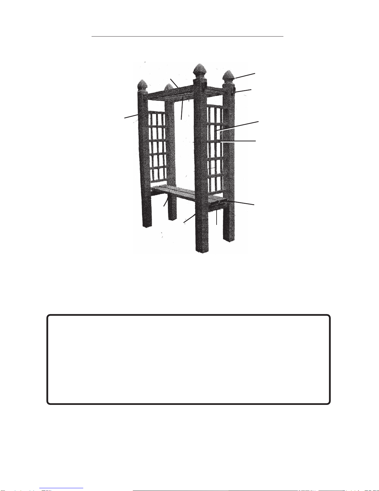
Overall Dimensions
Bench Max. Weight Capacity
Materials
Weight
58-5/8” Wide X 27-1/4” Deep X 97” High
200 Lbs.
White PVC-U.V. treated for Weather Protection
89 Lbs.

SKU91761 For technical questions, please call 1-800-444-3353. Page3
10. Warning: LocateTrelllis in a spot that is flat without an uneven surface, away from
electrical wires. Caution:Heavy winds could make theTrellis unstable.
11. Always distribute objects on Bench evenly. Uneven weight distribution could
cause toppling.Do not allow children to climb on theTrellis.
Warning:The warnings, cautions, and instructions discussed in this instruction
manual cannot cover all possible conditions and situations that may occur.It must
be understood by the operator that common sense and caution are factors which
cannot be built into this product, but must be supplied by the operator.
Unpacking
When unpacking, check to make sure the following parts are included.If any parts are
missing or broken, please call Harbor Freight Tools at the number on the cover of this
manual.
Assembly Instructions
1. Assemble all parts on a smooth surface to avoid scratching. These parts fit
together and no hardware is required.
2. “Ladder”Assembly: Use Cross Beams (2) and Bars (3) to form “ladder”.
Set aside.
See Figure A.
3. “Side Lattice” Assembly: Use four Bars (4) (horizontally), three Bars (5)
(vertically) with two Bars (11) (horizontally) at the top and bottom to build the
“lattice” assembly. Repeat instructions for the second side “lattice”.
See Figure B.
4. Still working with the parts on the ground, fit the Support Bar (7) between
the Posts (6).Fit the side “lattice”assembly between the two Posts (6).Repeat
for second side, “lattice” with Posts. Be sure all connections are secure.
See Figure B.
Figure A Figure B
Cross
Beams (2)
Bars (3)
Post (6)
Bars (4)
(horizontal) Bars(11)
(horizontal)
Bars(11)
(horizontal)
Bars (5)
(vertical)
Support Bar
(7)

SKU91761 For technical questions, please call 1-800-444-3353. Page4
5. Choose your location: The location site should be a flat, even surface (three
possible set-up options:
1.)
The Trellis can be free standing but
caution
should be taken:
Always distribute weight evenly on the bench to
prevent toppling.
2.)
Stand the Trellis upright and place in 6” deep holes.
Test that theTrellis is level.Pack dirt around Posts (6).
3.)
Place cement in the
holes before positioning the Posts (6). Test that the Trellis is level.
If you are
not experienced in setting up this type of product, it is recommended that you
seek the assistance of a qualified handyman for placement of your Trellis.
6. Place the assembled sides of the Trellis flat on the ground nearest to the
location. With an assistant, insert the “ladder assembly” into the Posts (6).
See Figure C.
7. There must be metal bars inserted in the two Braces (8) to support the weight
placed on the Bench (8).
See Figure D.
Snap the Bench (8) over the Support
Bar(7).
See Figure F–G.
8. Tap the Gothic Caps (1) on the end of each Post (6).
See Figure C.
Figure D
Figure F
Figure E
Metal
Bars
Clamps Bench (8)
Support
Bar (7)
Figure C
Gothic Cap (1) Ladder
Assembly
Post (6)

SKU91761 For technical questions, please call 1-800-444-3353. Page5
Parts List
Part # Description Qty.
1
2
3
4
5
6
7
8
9
10
11
4
2
9
8
6
4
2
2
4
4
4
4” X4” Gothic Cap
62” x 2” x 3-1/2” Cross Beam
21” X 1-1/2” x 1-1/2” Bar
25” x 1-1/2” x 1-1/2” Bar
47.5” x 13/16” x 1” Bar
89” x 4” x 4” Post
20-1/2” x 2” x 3-1/2” Support Bar
59” x 2” x 6” Bench
2 x 3-1/2” Cover
2” x 6” Cover
25” x 1-1/2” x 1-1/2” x 1-1/2” Bar
Support
Bar (7)
Bench (8)
Figure G Figure H
Cover (9)
Cover (10)
9. Place Covers (9) (not shown) over the ends of the “ladder” that are exposed.
Place the Covers (10) (not shown) over the Brace (8) pieces of the Bench.Tap
into place.
See Figure F.
10. AfterassemblyoftheTrellis is complete,test thatthe productis solid and stable
beforeusing theTrellis.

SKU91761 For technical questions, please call 1-800-444-3353. Page6
Assembly Drawing
(1)(2)
(11)
(7)
(9)
(8)
(3)
(4)
(6)
(10)
(5))
PLEASE READ THE FOLLOWING CAREFULLY
THEMANUFACTURERAND/ORDISTRIBUTORHASPROVIDEDTHEPARTSDIAGRAMINTHISMANUALAS
A REFERENCE TOOL ONLY. NEITHER THE MANUFACTURER NOR DISTRIBUTOR MAKES ANY
REPRESENTATION OR WARRANTY OF ANY KINDTOTHE BUYERTHAT HE OR SHE IS QUALIFIEDTO
MAKEANYREPAIRSTOTHEPRODUCTORTHATHEORSHE ISQUALIFIEDTOREPLACEANYPARTSOF
THEPRODUCT. INFACT,THEMANUFACTURERAND/ORDISTRIBUTOR EXPRESSLY STATESTHat ALL
REPAIRS AND PARTS REPLACEMENTS SHOULD BE UNDERTAKEN BY CERTIFIED AND LICENSED
TECHNICIANSAND NOT BYTHEBUYER.THEBUYERASSUMESALL RISK ANDLIABILITYARISINGOUT
OF HIS OR HER REPAIRS TO THE ORIGINAL PRODUCT OR REPLACEMENT PARTS THERETO, OR
ARISINGOUTOFHISORHERINSTALLATIONOFREPLACEMENTPARTSTHERETO.
NOTE: Some parts are listed and shown for illustration purposes only and are not
available individually as replacement parts.
Table of contents
Other One Stop Gardens Patio Furniture manuals