Onean Carver X User manual


WARNING!
The practice of jet powered watersports can be dangerous if the necessary
precautions are not taken. For this reason, we have prepared this user manual.
It will help you to know your new Carver X board and to use it correctly.
It contains information related to the assembly, care, use and maintenance of
your Carver X board. Please read this manual carefully before using the equipment.
It is the responsibility of the user to take the necessary measures for a safe use of the
products from Aquila Boards. The company will not be responsible for any damages
that may arise from the improper use of the equipment as well as its deterioration
due to incorrect maintenance.
!

1. Main Security checkS..............................................................5
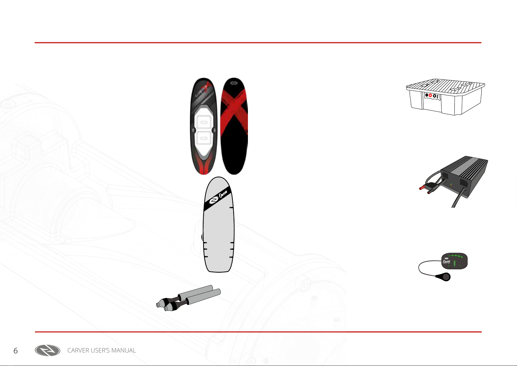
2. Packing LiSt
2.1. Carver board..........................................................................6
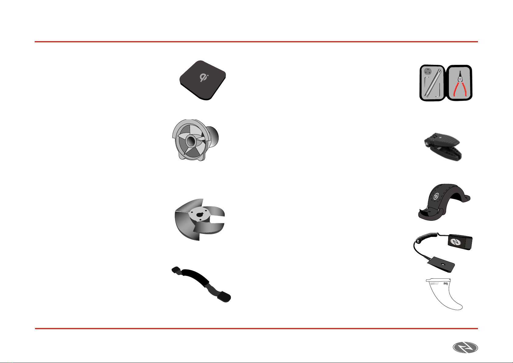
2.2. Jet Unit ...................................................................................7
2.3. batteries .................................................................................7
2.4. Charger ..................................................................................7
2.5. remote Control .....................................................................7
2.6. aCCessories .............................................................................7
3. FirSt aSSeMbLy
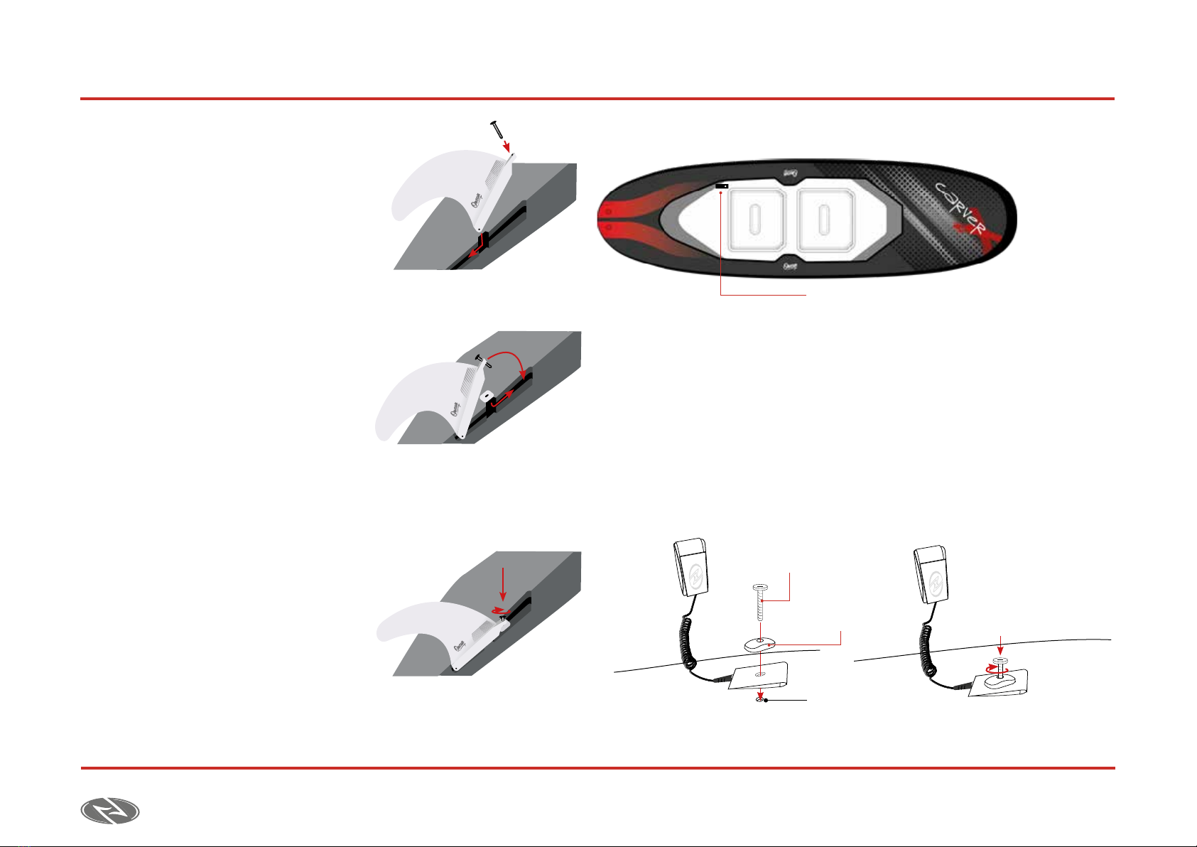
3.1. insert the fins.........................................................................8
3.2. install the leash ....................................................................8
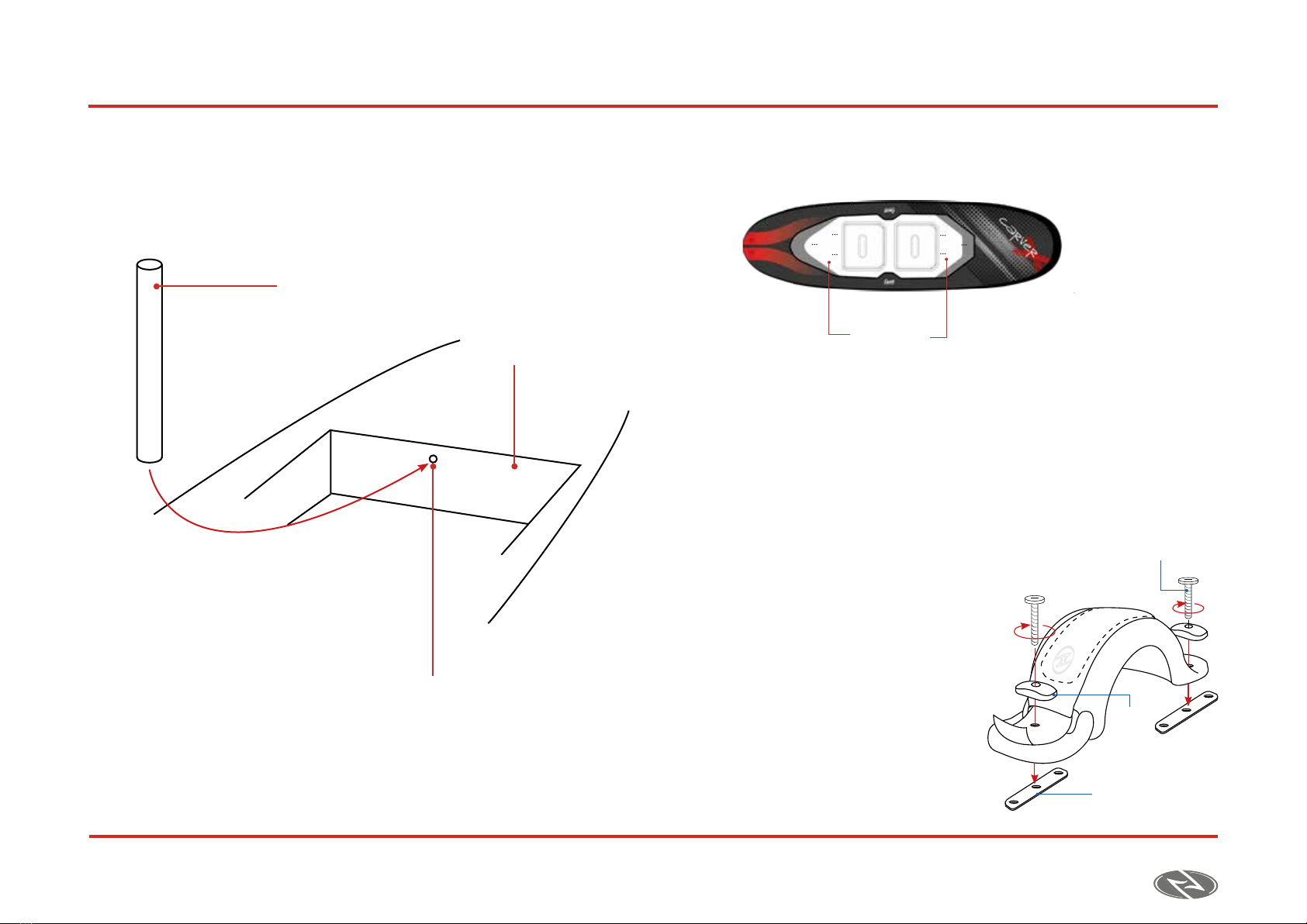
3.3. insert the battery magnet .....................................................9
3.4. Positioning the footstraPs ...................................................9
4. uSe and conFiguration oF the equiPMent
4.1. batteries ...............................................................................10
4.1.1 Battery transport and storage.......................................10
4.1.2 ConneCting/disConneCting the Battery...........................10
4.1.3 Battery Charge ...............................................................12
a) ConneCtion .......................................................................12
B) disConneCtion ...................................................................13
C) important..........................................................................13
4.2. Wireless Controller ...........................................................13
4.2.1. Controller Configuration ............................................13
a) synChronization ...............................................................14
B) maximum power................................................................14
C) Controller sensitivity ......................................................14
d) reset.................................................................................16
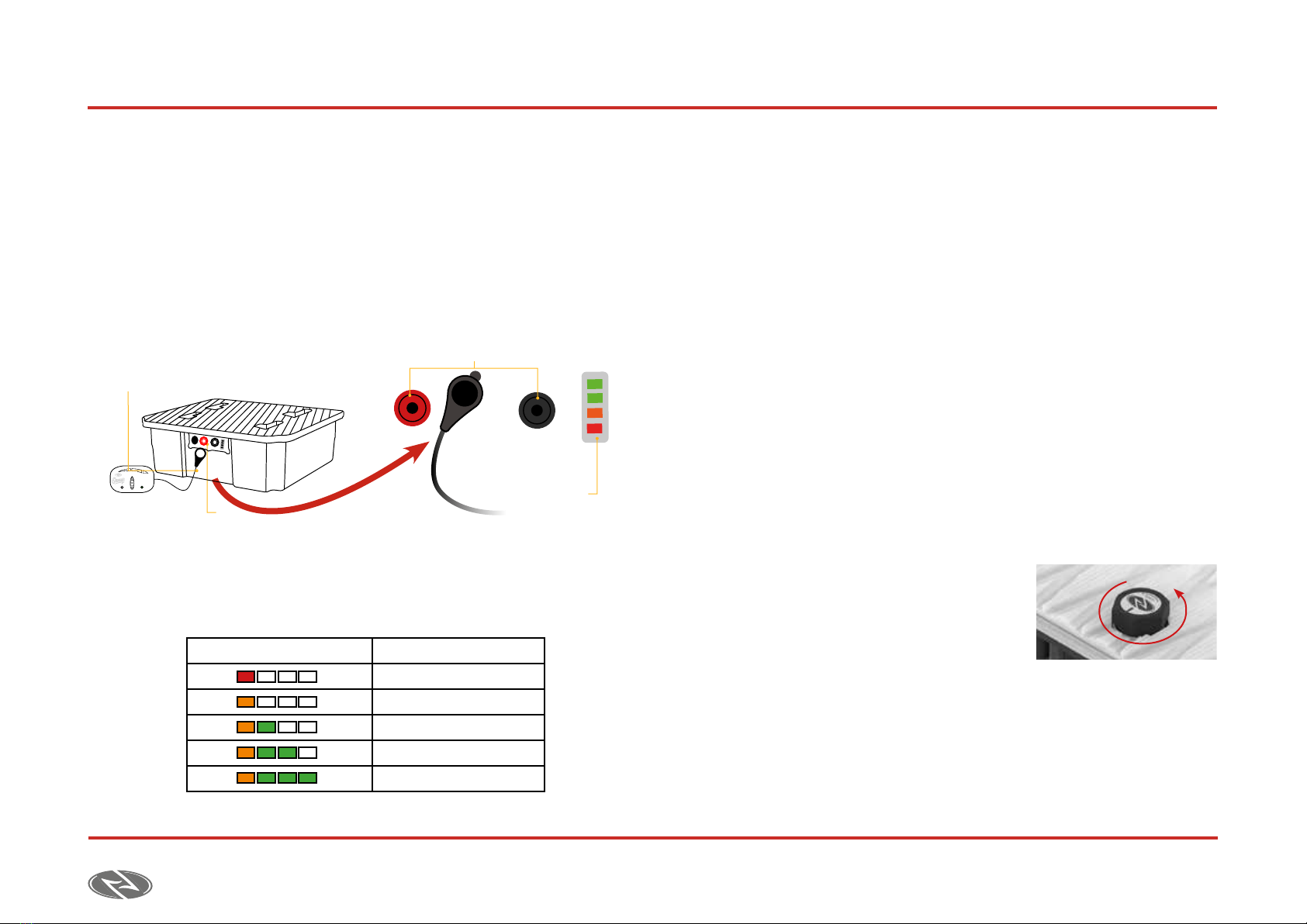
4.2.2. Charging the Controller ...............................................16
4.3. leash .....................................................................................17
4.4. seCUrity meChanisms ............................................................17
5. SaFety guideLineS
5.1. terms of Use ........................................................................18
5.2. before getting into the Water ............................................18
5.3. first Use................................................................................19
5.3.1. start up ..........................................................................19
5.3.2. tUrn ...............................................................................19
5.4. getting oUt of the Water ....................................................19
5.5. general seCUrity measUres ..................................................20
6. Maintenance oF the equiPMent
6.1. board maintenanCe..............................................................21
6.2. battery maintenanCe............................................................21
6.3. Wireless Controller maintenanCe ......................................22
7. rePairS and rePLaceMentS
7.1. imPeller.................................................................................23
7.1.1. UnmoUnting the impeller..............................................23
7.1.2. mounting the impeller...................................................24
7.2. ConneCtors ..........................................................................25
index

CARVER USER’S MANUAL 5
01
Main Security checkS
1. Main Security checkS
It is important to get familiar with the board’s security systems before starting
enjoying it. Please make sure you use the board following the instructions
provided in this manual.
• Always check the unit before entering the water. Make sure the
board, the safety disconnection system, the batteries and the wireless
controller are in good condition.
• Do not lend your equipment to anyone who has not been instructed
in the use of the Carver.
• When entering the water, you must avoid entering through wave break
areas and in case of doing so, you must always place yourself between
the board and the wave. This way the board will not harm you in case a
wave strikes you.
• Never practice this sport if the conditions exceed your skill level.
• Always wear the Leash attached while using the unit.
• When getting on the board you must always do it from one side, even
in areas of high depth. The water jet has great power and could cause
injuries.
• Never place your hands or feet near the impeller. The suction force
from the jet is very powerful and it could drag them to the interior. Even
with the batteries disconnected you must be aware of the impeller since
the leading edges are sharp and may cut.
• You must take into account that the board does not have a braking
system. Although you may discontinue to press the throttle, the board
will continue moving forward due to its inertia. This route can be relatively
long if you want to move from the glide status to the stopping one. It is
recommendable to slow down as you approach the target area where
you want to stop.
• Do not touch the steel tube right after use since it could be at elevated
temperature.

CARVER USER’S MANUAL
6
02 Packing List
2. Packing LiSt
The following describes a list of the components included with the equipment
and a description of them.
2.1. carver board
Construction with EPS core and laminated breglass
and epoxy full sandwich.
• Weight (without the batteries): 23 kg / 50 lbs
• Length: 240 cm / 7´8”
• Width: 70 cm / 27.7”
• Thickness: 15 cm / 5.9”
• Volume: 150 l
2.2. carver bag
• Semi rigid Carver Bag.
• Full bag inner padded reinforcement.
• Includes detachable wheels that ease
transporting.
2.3. 2 Jet unitS
• Nominal power: 5 kW (each)
• Nominal voltage: 44,4 VDC
• Static push: 240 N
2.4. batterieS
Short circuit, overcharge and temperature
protection. Waterproof.
• Type: multicell Litio-Ion
• Weight: 14 kg / 30 lbs
• Max. electric discharge: 130 A.
• Nominal capacity: 40.0 Ah
• Nominal voltage: 44.4 V
2.5. chargerS
Over voltage protection. Thermal protection. Short
circuit protection. Reverse polarity protection.
Charging indicator.
• Input power: 220-230 Vac (*Also available
110Vac)
• Charging current: 15 Amps
• Output voltage: 50,4 Vdc
2.6. reMote controL
Watertight. Thrust display. Battery display.
Pressure sensor Drop. Induction charging.
• Frequency: 2.4 Ghz
• Battery: LiPo 300mAh

CARVER USER’S MANUAL 7
02
Packing List
2.7. qicharger For the wireLeSS controLLer
Qi inductive technology charger that
simplifies charging into just setting your
controller down on the charging pad.
Input:5 V-2 A, Output: 5 V-1 A.
2.8. Stator+nozzLe
• Custom designed and CNC machined
out of high strength and corrosion
resistant tempered aluminum.
• Parts are hard anodized and xed joint
2.9. iMPeLLer
• 63.6 mm diameter. Custom designed
and CNC machined out of high strength
and corrosion resistant tempered
aluminum.
• Hard anodized, providing extra
corrosion resistance and an increased
surface hardness.
2.10. handLe
Made of highly durable thermoplastic
rubber, end webbing is doubled and
stitched for extra strength and security.
2.11. tooLing kit
• Contains conventional manual tools.
• Screw set and custom made tools necessary for
impeller extraction/insertion.
• All high strength and corrosion resistant.
• Ex. Impeller extractor tooling.
2.12. trigger
Ideal to minimize the eort of pressing the drop. Just
place the drop inside the trigger and press on it. Easy
to install, easy to remove.
2.13. FootStraPS
Pre-formed arch prevents collapsing. 7mm neoprene
padding. Internal adjustment system. Twist control
system.
2.14. LeaSh + Security key
7-Foot Coiled leash. Padded neoprene cu. Stainless
steel swivels to stop tangles. Custom made security
magnet pull system.
2.15. uS box FinS
Hard plastic and bre 6,5 inch UsBox ns.

CARVER USER’S MANUAL
8
03First Assembly
3.1. inSert the FinS
1. Insert the fin inside the finbox as
shown in the picture.
2. Insert the metallic square
in the finbox and move
it until it alignes the screw.
3. Fix the screw attaching the fin to the
board.
3.2. inStaLL the LeaSh
1. Insert the screw through the insert and hold the leash.
2. Align the holes with the leash insert located on the left hand lower side of
the board on the non-slippery surface.
3. Screw the piece to secure it.
Leash insert
Leash insert
Leash screw
Screw
insert

CARVER USER’S MANUAL 9
03
First Assembly
3.3. inSert the battery Magnet
Before using the unit for the first time, the cylindrical magnet must be
inserted in the hole inside the battery compartment.
3.4. PoSitioning the FootStraPS
The board incorporates inserts valid for both goofy and regular riders.
1. Depending on the style of riding, place the footstraps over the desired
inserts. One on the front of the board and one on the back.
2. Place the screw through the screw insert and hold the footstrap.
3. Align the holes with the footstrap insert.
4. Screw the footstrap to secure it.
Footstraps
inserts
Footstrap insert
Footstrap screw
Screw
insert
Battery magnet
Battery compartment
Insert for the
battery magnet

CARVER USER’S MANUAL
10
04 Use and ConfigUration of the eqUipment
4.1. batterieS
4.1.1. tranSPort and Storage oF batterieS
• In order to travel with the board, the batteries must be below 20% of charge.
This means that the LED bar must be only showing one LED.
Placing the drop near the battery display you will be able to check the
battery level.
• Do not transport the batteries inside the board unless you intend to
use it inmediately. Always use the side handle to transport the battery
pack. Do not pick it up by the top handle.
• Between uses you should store the batteries between 0ºC and 40ºC (32°F
and 104°F) always less than 3 months, in a ventilated area and with a
humidity between 0% - 80%. Do not store the batteries near metallic
objects.
4.1.2. connecting/diSconnecting the batterieS
Always charge the batteries and remote to the fullest before operating the
equipment.
Connection and disconnection of the battery:
1. Check the watertight seal and the battery housing to make sure they are
clean and free of sand. Make sure there aren´t any signs of damage before
use. Make sure there isn´t any water inside the battery compartment.
2. Turn the vent one full round counter-clock wise. Place the battery on the
pad, near the battery compartment where
the battery must be placed. Once the battery
is placed on the pad, grab it by the upper
handle and place in the battery compartment.
The blue LED on the front of the board
will light up indicating the connection.
Drop
Sensor
Charging
indicator
Battery connectors
SYNC BATTERY
Display Battery percentage
20%
40%
60%
80%
100%

CARVER USER’S MANUAL 11
04
uSe and conFiguration oF the equiPMent
3. Make sure the four pins are not visible and be aware of the
positioning while inserting it. Only one way is possible according to its
geometry.
4. Once the Battery is inserted in the board, insert
the four pins to lock the Battery. If the pins do
not enter easily, please, press down on the
battery so the watertight seal is sufficiently
compressed.
5. Close the vent completely, turning it clock wise to assure watertightness.
6. In order to ease the extraction of the batteries, turn the vent one full
round counte-clock wise. Pull from the upper handle perpendicularelly to
extract the batteries.
7. Keep the vent always closed in any other moment
and do not turn it more than three full turns.
Battery
Compartment
Board
Connectors
Antenna´s LED

CARVER USER’S MANUAL
12
04 Use and ConfigUration of the eqUipment
4.1.3 battery charge
WARNING!
Always connect the charger to the wall outlet rst and then to the
battery.
It is extremely important to respect the colors when connecting
the cable to the battery. Reverse polarity could have some
devastating consequences for the battery.
a) connection
1. In order to charge the battery it must be taken out from the board.
2. Insert the connector to the battery respecting the colors as shown in the
previous drawing (red with red and black with black).
3. When connecting the charger to the battery, The LEDs will
light up indicating a successful connection. In case of the
LEDs not lighting up, please make sure that the charger
is properly plugged to the wall outlet and to the battery.
4. Once the battery is connected, the display LED
indicator will light up indicating the charge (img.
A) until fully charging it, turnining to green (img. B).
5. The LEDs in the battery will progressively light
up as the battery is being charged.
6. When the battery is fully charged the LEDs will turn off and
you must proceed to disconnect the battery.
!
Frontal View
AC Cable
DC Cable
Static Yellow light indicates
normal charging
Green LED lights up when battery is
fully charged
¨A¨Charging “B” Full charge
Charging indicator
Connector body
Battery connectors

CARVER USER’S MANUAL 13
04
uSe and conFiguration oF the equiPMent
b) diSconnection
Avoid pulling from the cable, always pull
from the connector body.
c) iMPortant
Always supervise the charge, do not leave
the batteries unnatended while charging.
• The batteries does not need to be fully discharged before charging. A
Lithium Ion battery doesn´t have memory eect. This means that the
maximum energy capacity won´t be aected if its charged after not being
fully discharged.
• Make sure that the batteries do not remain to be connected to the
charger after the charge has been completed.
• Always remember to close the battery rubber connector covers before
use.
• The temperature use for the batteries must always remain between 0ºC
and 60ºC (32ºF y 140ºF).
• Extreme temperatures will aect the batteries life, specially during
charge. Avoid charging the batteries while being exposed to direct sunlight
or extreme high or low temperatures. The charge is recommended to be
carried out with temperatures (between 10ºC y 45ºC / between 50ºF y
113ºF).
• Do not overdischarge the batteries. Do not continue riding once the
power starts to decrease and the LEDs on the top bar begin to blink, this
has been proven to decrease the battery’s capacity over time. This is an
extra energy resource which must be used only for emergencies.
4.2. wireLeSS controLLer
To activate the board you must press on the drop. The power of the Jet will
depend on the amount of pressure done on the drop.
4.2.1. controLLer conFiguration
Through the wireless controller you can set the maximum power for the Jet
and also adjust dierent proles.
In order to access the configuration menu, you must follow the following
indications. Always with the batteries initially disconnected:
1. With the controller totally off (no LEDs ) place
the drop over the logo.
2. On this position, press on the drop
until the rst LED of the board display
SYNC BATTERY
Drop
Sync
Controller
battery
Board Battery
Power
Indicators
SYNC BATTERY
1
Connector
body
Cable

CARVER USER’S MANUAL
14
04 Use and ConfigUration of the eqUipment
on the controller beings to blink. At
this moment, the LED bar will begin to
progressively light up. Each position
represents a different function.
a) Shynchronization. 1St Led bLinking
Once the rst LED begins to blink, you
must press on the drop again to access the submenu.
In this submenu, the controller will begin to search for a board for a few
seconds and the sync LED will begin to blink.
As the sync LED is blinking the battery must be inserted to complete
the synchronization (see 4.1.2.).
Once the board is synched, both LEDs will blink at a higher pace
indicating that the process has been successfully completed.
b) MaxiMuM Power. 2 LedS bLinking
Once that the rst two LEDs are
ashing you must press on the
drop to access this submenu.
The power bar will progressively light up. Press on the drop to set
the desired value according to the following description.
c) controLLer SenSitivity. 3 LedS bLinking
Once the rst three LEDs are ashing you must press on the drop to
access the submenu.
The power bar will progressively light up. Press on the drop to set
the desired value according to the following description.
• 1 LED: Staggered 1.
• On this profile we have discretized the power levels of
the jet in 5 different ranges of pressure on the drop. It
allows us to control and hold the pressure on each range.
SYNC BATTERY
LED Blinking
2
SYNC BATTERY
LEDs Power [W] Display
1 LEDs 1.500
2 LEDs 2.300
3 LEDs 5.100
4 LEDs 7.400 Factory Settings
5 LEDs 10.000
Power %
Low
0
20
40
60
80
100
Medium High
Staggered 1

CARVER USER’S MANUAL 15
04
uSe and conFiguration oF the equiPMent
• 2 LEDs: Staggered 2. This prole has three power levels. The
rst one allows us to activate the jet at a low power in order to go at
slow speeds (for example, to go from shore to a safe cruising area). The
second power level will allow us to decrease the power consumption
once planing is reached so we can get more battery life.
• 3 LEDs: Staggered 3. This is a prole similar to the previous
one with the difference that the second power level is at a higher
power. In case that ¨Staggared 2¨doesn´t allow us to reach planing we
could use this one.
• 4 LEDs: 100%/0%. The jet will from 0 to 100% power
by pressing on the drop. This will be the most comfortable
setting for those wanting maximum power throughout
the ride but the battery life will be compromised.
• 5 LEDs: lineal. On this profile, the jet reacts
lineally to the pressure on the drop. It requires a bit more
of skills in order to use the entire range appropriately.
Power %
Low
0
20
40
60
80
100
Medium High
Staggered 2
Power %
Pr
Low
0
20
40
60
80
100
Medium High
Staggered 3
Power %
Low
0
20
40
60
80
100
Medium High
Staggered 4
Power %
Low
0
20
40
60
80
100
Medium High
Staggered 5

CARVER USER’S MANUAL
16
04 Use and ConfigUration of the eqUipment
d) reSet. 4 LedS bLinking
3. Once the controller has reached all 4 LEDs, all
the information will be stored and all LEDs turn o.
If you do not want to change any of these parameters you don’t need
to do this process again, it will remain in the internal memory of the
controller.
4. To check the current status you can repeat the step 1 but press on the
drop only one time instead of holding it pressed. The controller will show
the preferences for each category.
5. Always use the controller inside the controller wristband.
6. Always secure the wirstband before use.
7. In order to activate the jet, press on the drop with the index nger and
thumb.
8. The power will vary depending on the pressure placed on the drop.
4.2.2 . charging the controLLer
1. Connect the Qi charger through a USB.
2. Place the controller on the center of the Qi as shown in the drawing
below.
3. When charging, the green LED will begin to blink.
4. Once the controller is fully charged, the LED will turn o.
5. To check the status of the battery of the controller please pick it up and
press on the drop to see the battery LED-.
SYNC BATTERY

CARVER USER’S MANUAL 17
04
uSe and conFiguration oF the equiPMent
4.3. LeaSh
1. Attach the leash right below the knee of the front leg, as shown on the
drawing below.
2. Once the rider is ready to use the board, place the security magnet
key on the board.
The magentic key is a security mechanism, the jet will not activate if this
key is not properly placed.
3. In case of fall, the magnetic key will detatch, stopping the jet. Once the
rider is back on the board ready to continue its use, the magnetic key
should be properly placed again.
4.4. Security MechaniSMS
The board has various security mechanisms that stop it automatically in case
of:
• Engine overheat.
• Battery overheat.
• Loss of communication between the controller and board.
• Tightening of the jet when starting or blockage of the turbine due to an
external object.
• Magnetic key disconnection. In case of fall, it will automatically disconnect.
• In case of fall, or if the controller is submerged, the jet will stop as a
security measure.
If any of the previous cases happes during use, the jet will automatically stop.
This security block will remain until the above causes are solved.
In order to reactivate the board, the security magnet must be disconnected
and reconnected.
Magnetic Key
Magnetic Key
Connector

CARVER USER’S MANUAL
18
05Safety GuidelineS
5.1 terMS oF uSe
• The Carver board is suitable for fresh ans salt water use.Ideal conditions
are with no wind and at water.
• Be aware of local regulations before using and the areas where this
kind of equipment is eligible for use.
• Taking into account that the jet sucks water through the intake it is
important to look for water is free of floating elements at which to
practice this sport. Mentioned oating elements could cause damage to
the rotating elements inside the waterjet.
• The Carver Board has not been designed to be used at wave breaking
areas. Please look for an area of calm waters at which to entry the water.
• Taking into account the high speeds and maneuverability of the board, it
important to use the Carver at large open spaces free of obstacles.
• Be aware of the tides. With the sea level changes, new obstacles may
arise depending on the tide.
• Avoid using this product in the vicinity of other people, vessels or objects
that may compromise the user’s or board’s security.
• Avoid crowded beaches and always respect the navigation channels.
• In case of entering the water throught the beach, make use of the marked
areas that allow the entry and exit of watercrafts.
• It is advisable not to overturn/ip the board in the water.
• Do not grab or lift the board by the discharge connectors.
• Do not remove the goretex vent in the back of the board.
5.2. beFore getting into the water
• Make sure the leash and the magnetic security key (kill switch) are in good
condition.
• Make sure the remote works properly before heading to the water.
• Make sure to assemble your equipment over grass or sand in order not
to damage it. Any damage caused by manipulating your equipment over
a hard and abrasive surface will not be covered by the warranty.

CARVER USER’S MANUAL 19
05
Safety GuidelineS
5.3. FirSt uSe
5.3.1. Start uP
During rst uses it is recommendable to use it on your knees.
1. Get on top of the board with the leash attached and the magnetic
key connected. You should place your knees on each side of the front
footstrap.
2. After being positioned, press on the drop to activate the jet.The power
will vary depending on the pressure being put on the drop.
3. Once you gain speed you can progressively stand on it.
Make sure not to accidentally press on the drop while getting on or o
the board.
5.3.2. turn
Before turning, make sure there is enough space to do so
and not interfere with the trajectory of any other vehicle.
Shift the weight towards the side where you intend to turn to ease the
movement. The more speed, the easier it is to turn. The board turns like a
conventional board.
5.4. getting out oF the water
• Do not activate the jet outside of the water. The propulsion system is
not meant to be used outside of the water, this could signicantly damage
the jet.
• After a long use going full thrust, it´s recommendable to wait at least
one minute for the jet not to overheat.
• When the jet reaches high temperatures, an inner fan is automatically
activated for heat dissipation purposes. In order for this process to be
done appropriately, the jet must be in contact with the water.
• It is not recommendable to step on the battery surface. Although
it’s designed to hold weight, when stepping on it, the watertight seal
compresses facilitating water to get in.

CARVER USER’S MANUAL
20
05Safety GuidelineS
5.5. generaL Security MeaSureS
• This board could reach high speeds. It is recommendable to use a life
vest and a helmet while operating this product.
• Do not go further o shore than you can return swimming and always
have someone watching from shore. Do not operate this product alone.
• Be aware of climate changes or any other sudden change in the located
area (tides, shallow waters,..). Do not use this product while electric
storms.
• Do not use this product near swimmers or scuba divers.
• Make sure that the water is deep enough to operate this board, be
aware of coral reefs.
• Do not operate in areas of high current or waves. The Carver is not
meant to be used to surf waves. In case of being tilted by a wave, the
rider could suer severe damages.
• Do not use behind another board. In case of doing it, make sure you
have enough space to turn in case the rider ahead falls.
Table of contents
Popular Accessories manuals by other brands

LORD
LORD MicroStain 3DM-GX5-45 quick start guide

Fastus
Fastus TOF-L450 Series instruction manual

ORION TELESCOPES & BINOCULARS
ORION TELESCOPES & BINOCULARS 5567 quick start guide

Fluke
Fluke RUBBER SHOE ACCESSORY PN 3125710 instruction sheet

Huawei
Huawei RRU3942 Hardware description

Cumberland
Cumberland EDG-177 quick start guide