oneConcept 10000345 User manual

INSTRUCTION MANUAL
10000345/10000346/10001810/10001818

Specifications
AUDIO POWER SPECIFICATIONS
Outputs 2/4channel Amplifier
this unit had built-in power regulator which converts the power supplied by the DC12v car battery into high speed
pulses
using a MOS-FET semiconductor switch, These pulses are stepped up by the built-in pulse transformer and
separated
into both positive and negative power supplies before being converted into direct current again ,this is to regulate
fluctuating voltage from the car battery, This light weight power supply system provides a highly efficient power
supply
with a low impedance output.
Pulse power supply
Maximum power output of 300 watts pre channel (at 4 ohm)
This nuit can be used as a bridging amplifier with a maximum output of 600 watts.
Direct connection can bemade with the speaker output of your car audio if it is not equipped
with a line output (High level input connection).
Built-in variable LPF low- pass filter), HPF(high-pass filter)and low boost circuit .
Protection circuit and indicator provided.
Pulse power supply* for stable, regulated output power.
Features
300 watts per channel minimum continuous average power into 4 ohms, both channels driven
from 20Hz to 20kHz with no more than 0.04% total harmonic distortion per Car Audio Ad Hoc
committee standards.
Other specification
POWER OUTPUT AND TOTAL HARMONIC DISTORTION
2/4 channel Power Amplifier
MAX Power Output:2(300W ) 4(600W)
RMS Power Output:4 25W (4 OHM)
2 25W (4 OHM)
4 90W
2 90W
High Pass:120Hz-3KHz
Low Pass: 50Hz-250Hz
S/N Ration:90dB
Frequency Response:10Hz-30KHz
Low Input Sensitivity/impedance:120mV-1.0V 10K
Load Impedance:2-8
Damping factor>120
Power Supply:DC10.5-15V
Dimension:100 85 40mm
P.1

Troubleshooting Guide
The following checklist will assist in the correctiono f most problemsw hich you may encounter
with you unit, Before going through the connection and operating procedures.
Problem Cause / solution
The power indicator does not light up. The fuse is loose or blown -- fasten the fuse or change
it with a new one
The ground lead is not securely connected -- fasten a
metal point of the car
the voltage going into the remote terminal is too low
the connection master unit is not turned on, -turn on
the master nuit.
the system employs too many amplifiers.--use a relay.
Check the battery voltage (10.5-15V)
outout off, The protection indicator light
up in red
The speaker outputs are short -circuited.--Turn off power
switch, Rectify the cause of the short -circuit and correct.
The unit heats up abnormally or operating temperature.
Use speakers with suitable impedance--2~8 (stereo),
4~8 (when used as a bridging amplifier)
make suer to place the unit in a well ventilated location.
Alternator noise is heard.
RCA pin cords.--Tidy these connecting leads and keep
the leads away from the cords.
The ground lead not securely connected--Fasten
the ground lead securely to a metal point of the car.
Negative speaker leads are touching the car chassis.
--Keep the leads away from the car chassis.
The sound is muffled.
The sound in too low.
Location and function of controls
1. POWER indicator
Lights up in green during operation.
2. FILTER selector switch
when the switch is in the LPF positions. the filter
is set to low-pass.When in the HPF position,
the filter is set to high-pass.
3. LEVEL adjustment control
the input level can be adjusted with this control when using source
equipment
made by other manufacturers, Tun it to MAX when the output level of the car
audio seems low.
The power connecting leads are installed too close to the
The FILTER switch set to the "LPF" position.
The level adjustment control is set "MIN"position.
P.2
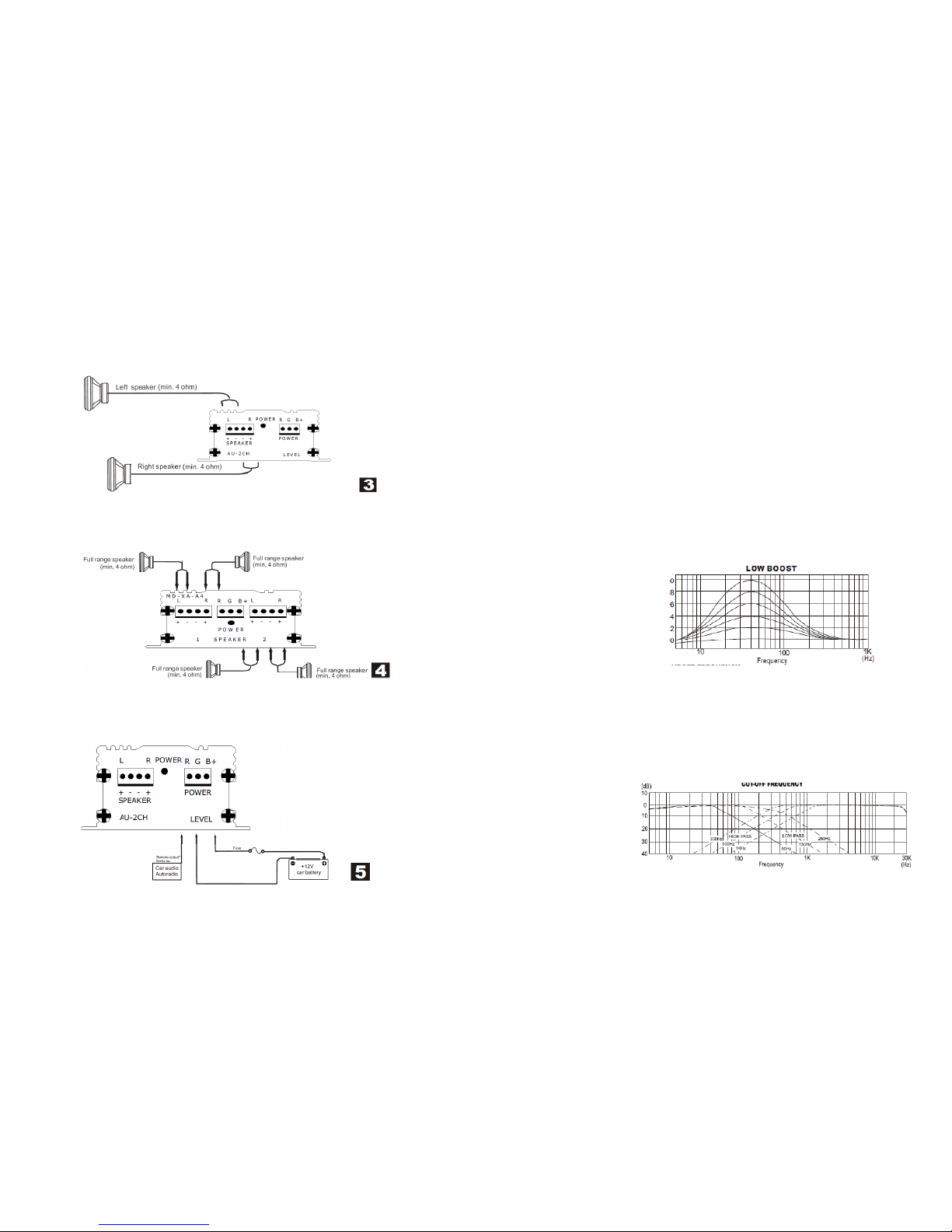
Notes on the power supply
Connect the +12V power supply lead only after all the other leads have been connected,Be sure to
connect the ground lead of the unit securely to a metal point of the car, A loose connection may
cause a malfunction of the amplifier,
Be sure to connect the remote control lead of the car audio to the remote terminal,
When using a car audio without a remote output on the amplifier, connect the remote input
terminal(REMOTE)to the accessory power supply.
Use the power supply lead with a fuse attached(40A),
Place the fuse in the power supply lead as close as possible to the car battery,
Make sure that the leads to be connected to the +12Vand GND terminals of this unit are larger than
10-Gauge (AWG-10)or have a sectional area of more than 5 (mm)
Precautions
This unit is designed for negative ground 12V DCoperation only.
Use speakers with suitable impedance.--2 to 16ohm(stereo).
Do not connect any active speakers (with built-in amplifier)to the speaker terminals of the nuit.
Avoid installing the unit where:
--it would be subject to high temperatures such as from direct sunlight or hot air from the heater.
--it would be exposed to rain or moisture.
--it would be subject to dust or dirt, lf your car is parked in direct sunlight and there is a considerable
rise
in temperature inside the car, allow the unit to cool down before use.
When installing the unit horizontally, be sure not to cover the fins with the floor carpet etc.
lf this unit is placed too close to the car radio, interference may occur. ln this case, relocate the
amplifier away from the car radio .
lf no power is being supplied to the master unit, check the connections.
This power amplifier employs a protection circuit to protect the transistors and speakers if the
amplifier malfunctions.
Do not attempt to test the protection circuit by covering the heat dink or connecting improperloads.
Do not use the unit on a weak battery as its optimum performance depends on s good power
supply.
For safety reasons, keep you car audio volume moderate so that you can still hear sounds outside
your car.
*Protection circuit
this amplifier is provided with a protection circuit that operates in the following cases:
--when the unit is overheated
--when a DC current is generated
--when the speaker terminals are short circuited.
The PROTECTOR indicator lights up in red and the unit will shut down.
lf this happens, turn off the connected equipment, take out the cassette tape or disc, and determine
the cause of the malfunction, lf the amplifier has overheated, wait until the unit cools down before
use.
Installation
Before installation
Mount the unit either inside the trunk or under a seat.
Choose the mounting location carefully so the unit
will not interfere with the normal movements of the
driver and it will not be exposed to direct sunlight or
hot air from the heater.
Do not install the unit under the floor carpet, where
the heat dissipation from the unit will be considerably impaired.
P.7

2-speaker system
For details on the settings of switches and controls, refer to "Location and function of controls."
4-speaker system
For details on the settings of switches and controls, refer to "Location and function of controls."
Note
in this system, the volume of subwoofers will be controlled dy the car audio fader control
power connection leads
lf you have the factory original or some other car audio without a remote out-put on the amplifier,
connect the remote input terminal (REMOTE) to the accessory power supply. P.6
Fuse replacement
lf the fuse blows, check the power connection and replace the fuse, lf the fuse blows again after
replacement,
there may be an internal malfunction, ln such a case, consult your nearest goods dealer.
Warning
when replacing the fuse, be sure to use one matching the amplifier stated above the fuse
holder, Never use a fuse with an amperage rating exceeding the one supplied with the
unit as this could damage the unit.
Caution
Before making any connections, disconnect the ground terminal of the car battery to avoid short
circuits,
Be sure to use speakers with an adequate power rating, lf you use small capacity speakers, they
may be
damaged.
Do not connect the "-" terminal of speaker system to the car chassis and do dot connect the "-"
terminal of the
right speaker with that of the left speaker.
ln stall the input and output cords away from the power supply lead as running them close together
can
generate some interference noise.
This unit is a high powered amplifier , Therefore, it may not perform to its full potential if used with
the speaker
cords supplied with the car.
lf your car is equipped with a computer
system for navigation or some other
purpose, do not remove the ground wire
from the car battery, lf you disconnect the
wire, computer memory may be erased, To
avoid short circuits when making
connections, disconnect the +12v power
supply lead until all the other leads have
been connected.
Make the terminal
connections as illustrated below.
Note
tighten the screws firmly, but be
careful not to apply too much force*
as doing so may damage thee screws.
the torque value should be less
than 1 mm
First, place the unit where you plan to
install it, and mark positions of the four
screw holes on the surface of the mounting
board (not supplied), Then drill the
hoes approximately 3mm in
diameter and mount the unit onto
the board with the supplied
mounting screws.
The supplied mounting screws are
15mm long, Therefore, make sure
that the mounting board is thicker
than 15mm.

Input.connections
Line input connection(with speaker connectlon 3 )
Line input connection (with speaker connectlon 1, 2 or 4 )
P.4
Speaker.connections
4-speaker system
For details on the settings of switches and controls, refer to "Location and function of controls."
3-speaker system
For details on the settings of switches and controls, refer to “Location and function of controls.”
Notes
in this system, the volume of the subwoofer will be
controlled by the car audio fader control.
ln this system, the output signals to the subwoofer are a combination
of both the REAR L and R INPUT jack or the REAR high level input connector signals. P.5
This manual suits for next models
3
Table of contents
Other oneConcept Car Amplifier manuals
Popular Car Amplifier manuals by other brands

Sound Storm
Sound Storm Force F1200M user guide

BOSSCO
BOSSCO Chaos Wired CW1250 user manual

Audiodesign
Audiodesign Hifonics AXi5005 owner's manual

Sound Storm
Sound Storm M1082 user manual

Audiosystem
Audiosystem C0-95.2 owner's manual

Diamond Audio Technology
Diamond Audio Technology D7054 installation manual