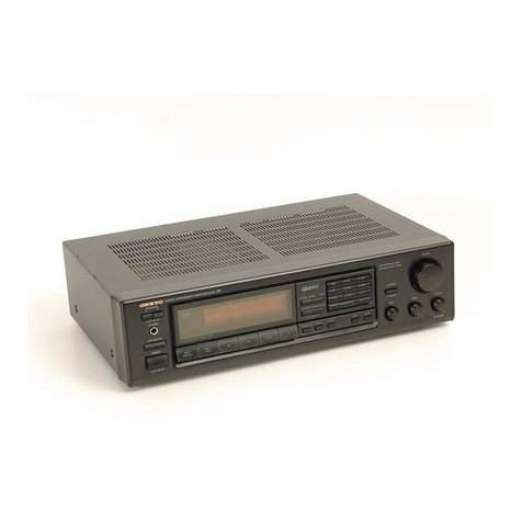
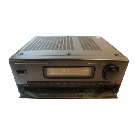
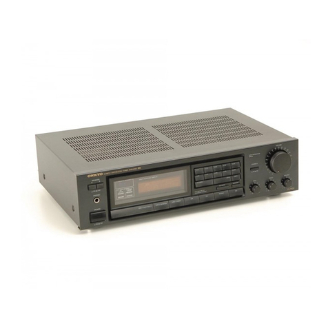
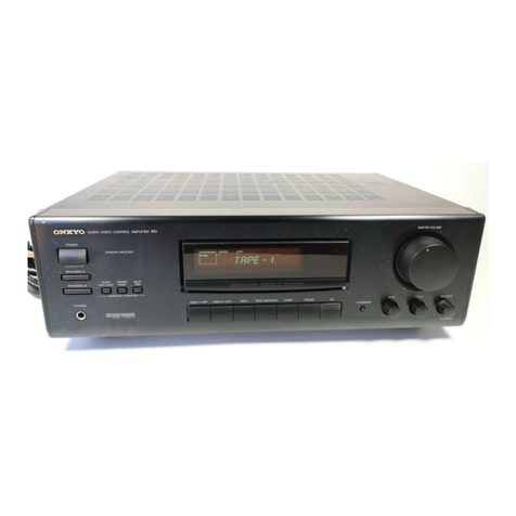
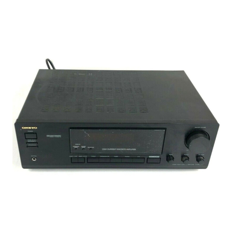
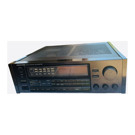
Onkyo TX-902 User manual

RCE

@
Congratulations
on
your
purchase
of
the
ONKYO
TX-902,
TX-
900
Tuner-
Amplifier.
@
Please
read
this
manual
thoroughly
before
making.
connections
and
turning
poweron.
®
Following
the
instructions
in
this
manual
will
enable
you
to
obtain
optimum
performance.
a
ete
and
listening
enjoyment
from
your
new
TX-902,
TX
900.
e
Please
retain
this
manual
for
future:
haere
reference.
CON
TEN
TS
-
Features
Precautions
Before
using
this
unit
System
connections
Control
positions
and
names
Operations
Troubleshooting
guide
Specifications
Features
®
Pienty
of
Clean
Power
TX-902:
50
watts
of
continuous
power
per
channel
into
8
ohms
with
no
more
than
0.2%
total
harmonic
distortion
(2
x
65
watts
continuous
power
at
4
ohms
DIN)
TX-900:
40
watts
of
continuous
power
per
channel
into
8
ohms
with
no
more
than
0.3%
total
harmonic
distortion
(2
x
55
watts
continuous
power
at
4
ohms
DIN)
@
Discrete
Output
Stage
Important
SafeEQuardsS...........
cc
ccceccceecssnsseeeeeeeeeeteees
Pet
ENO
HATHA
RR
EAEE
HHT
AHHH
AHSHHOHTEEREHPHE
RARE
EER TER
ERASE
TeEHEEOH
ei
=
ghic
oe
ats
1
instead
of
the
less
expensive
IC
power
amp
circuitry
used
in
some
receivers,
the
TX-902
and
TX-900
feature
output
stages
composed
of
discrete
components.
Not
just
an
off
—
the
—
shelf
chip,
the
circuit
design
of
the
output
stage
is
optimized
for
the
specific
requirements
of
the
tuner
amplifier
to
assure
that
the
TX-902
and
TX-900
can
not
only
deliver
sufficient
power,
but
also
safely
drive
even
low
impedance
loads.
@
30-Station
FM/AM
Random
Preset
Tuning
®
Classified
Memory
Preset
The
memory
presets
are
divided
into
six
classes,
A
through
F,
which
can
be
used
for
different
types
of
programs
(rock,
news,
classical,
etc.).
Or
each
member
of
the
family
can
have
a
separate
class
(class
A
for
Dad,
class
B
for
Mom,
class
D
for
Junior).
Any
preset
station
can
be
assigned
to
any
class.
®
Direct
Access
Tuning
Using
Numeric
Suttons
Instead
of
using
the
UP
or
DOWN
tuning
buttons
to
scan
through
the
available
frequencies
until
the
desired
station
is
located,
Direct
Access
Tuning
lets
you
punch
in
the
broadcast
frequency
directly
using
the
numeric
buttons.
For
example,
103.50
MHz
can
be
selected
by
simply
pressing
the
1,
0, 3,
5
and
O
buttons.
@
APR
(Automatic
Precision
Reception)
System
Onkyo’s
exclusive
APR
system
lets
every
FM
broadcast
sound
its
best.
Its
built
—
in
electronic
brain
monitors
the
signal
and
selects
the
optimum
settings
for
RF
local/DX
and
stereo
auto/mono.
The
APR
system
settings
are
shown
by
indicators
on
the
front
panel.
Two
Pairs
of
Speaker
Output
Terminals
Loudness
Control
Important
safeguards
“WARNING”
“TO
REDUCE
THE
RISK
OF
FIRE
OR
ELECTRIC
SHOCK,
DO
NOT
EXPOSE
THIS
APPLIANCE
TO
RAIN
OR
MOISTURE.”
CAUTION
“TO
REDUCE
THE
RISK
OF
ELECTRIC
SHOCK,
DO
NOT
REMOVE
COVER
(OR
BACK).
NO
USER-SERVICEABLE
PARTS
INSIDE.
REFER
SERVICING
TO
QUALIFIED
SERVICE
PERSONNEL.”
@
For
models
having
power
cord with
a
polarized
plug.
CAUTION:
To
PREVENT
ELECTRIC
SHOCK
DO
NOT
USE
THIS
(POLARIZED)
PLUG
WITH
AN
EXTENSION
CORD,
RE-
CEPTACLE
OR
OTHER
OUTLET
UNLESS
THE
BLADES
CAN
BE
FULLY
INSERTED
TO
PREVENT
BLADE
EXPOSURE.
Six
Program
Inputs
Including
Video
Sound
with
Logic
Controlled
Feather-Touch
Keys
f2|
Compatible
Wireless
Remote
Control
Included
(TX-902
only)
ATTENTION
FOR
BRITISH
MODEL
@
Replacement
and
mounting
of
an
AC
plug
on
the
power
supply
cord
of
this
unit
should
be
performed
only
by
qualified
service
personnel.
@
IMPORTANT:
The
wires
in
the
mains
lead
are
coloured
in
ac-
cordance
with
the
following
code:
Blue:
Neutral
Brown:
Live
As
the
colours
of
the
wires
in
the
mains
lead
of
this
apparatus
may
not
correspond
with
the
coloured
markings
identifying
the
terminals
in
your
plug,
proceed
as
follows:
The
wire
which
is
coloured
blue
must
be
connected
to
the
terminal
which
is
marked
with
the
letter
N
or
coloured
black.
The
wire
which
is
coloured
brown
must
be
connected
to
the
terminal
which
is
marked
with
the
letter
L
or
coloured
red.
@
This
apparatus
complies
with
requirements
of
EC
directive
87/308/EEC.
lads
o
Lenddn
MS

Observe
the
following
precautions
to
obtain
troublefree
performance
for
many
years.
1,
Avoid
places
subject
to
direct
sunlight
or
extremely
high
or
low
temperatures.
.
Avoid
damp
or
dusty
places
and
places
directly
affected
by
vibrations
from
the
speakers.
In
particular,
avoid
placing
the
unit
on
or
above
one
of
the
speakers.
.
Avoid
unstable
locations
and
high
places
from
which
the
unit
could
fail.
_
Ventilation
—
The
unit
should
be
situated
so
that
its
location
or
position
does
not
interfere
with
proper
ventilation.
For
ex-
ample,
the
unit
should
not
be
placed
on
a
bed,
sofa,
rug
of
similar
surface
that
could
block
the
ventilation
openings
or
placed
in
a
built-in
installation,
such
as
a
bookcase
or
cabinet,
that
could
impede
the
flow
of
air
through
the
ventilation
openings.
.
Heat
—
The
unit
should
be
situated
away
from
heat
sources
such
as
radiators,
heat
registers,
or
other
appliances
(including
amplifiers)
that
produce
heat.
Precautions
4
Warranty
Card
The
serial
number
is
written
on
the
rear
panel
of
this
unit.
Copy
the
serial
number
and
model
number
onto
your
warranty
card
and
keep
it
in
a
safe
place.
Recording
Copyright
Recording
of
copyrighted
material
for
other
than
personal
use
is
illegal
without
permission
of
the
copyright
holder.
.
AC
Fuse
The
fuse
is
located
inside
the
chassis
and
is
not
user
serviceable.
If
power
does
not
come
on,
contact
your
Onkyo
service
center.
.
Care
From
time
to
time
you
should
wipe
off
the
front
and
rear
panels
and
the
cabinet
with
a
soft
cloth.
For
heavier
dirt,
dampen
a
soft
cloth
in
a
weak
solution
of
mild
detergent
and
water,
wring
it
out
dry,
and
wipe
off
the
dirt.
Following
this,
dry
immediately
with
a
clean
cloth.
Do
not
use
rough
material,
thinners,
alcohol
or
other
chemical
solvents
or
cloths
since
these
could
damage
the
finish
or
remove
the
pane!
lettering.
.
Power
WARNING
BEFORE
TURNING
ON
POWER
FOR
THE
FIRST
TIME,
READ
THE
FOLLOWING
SECTION
CAREFULLY.
Some
models
are
designed
for
use
only
with
the
power
supply
voltage
of
the
region
where
they
are
sold.
European
models
(except
U.K.):
Canadian
models:
U.K.
&
Australian
models:
Worldwide
models:
AC230V,
50Hz
AC120V,
60Hz
AC
240V,
50Hz
120
and
220V
switchabie,
50/60Hz
®
Voitage
Selector
(Rear
Panel)
Worldwide
models
are
equipped
with
a
voltage
selector
to
conform
with
jocal
power
supplies.
Be
sure
to
set
this
switch
to
match
the
voltage
of
the
power
supply
in
your
area
before
turning
the
power
switch
on.
Voltage
is
changed
by
sliding
the
groove
in
the
switch
with
a
screwdriver
to
the
right
or
left.
Confirm
that
the
switch
has
been
moved
all
the
way
to
the
right
or
left
before
turning
the
power
switch
on.
Models
without
a
voltage
selector
can
only
be
used
in
areas
where
the
power
supply
is
the
same
as
that
of
the
unit.
6.
7.
8.
@
Tuning
Step
Frequency
Switch
(Bottom)
Cleaning
of
the
internal
parts
should
be
performed
only
by
qualified
service
personnel.
:
Spillage
—
Care
should
be
taken
so
that
objects
do
not
fall
and
liquids
are
not
spilled
into
the
enclosure
through
the
openings.
Damage
Requiring
Service
—
The
unit
should
be
serviced
by
qualified
service
personnel
when:
A.
The
power
supply
cord
or
the
plug
has
been
damaged;
or
B.
Objects
have
fallen
or
liquid
has
been
spilled
into
the
unit;
or
C.
The
unit
has
been
exposed
to
rain;
or
D.
The
unit
does
not
appear
to
operate
normally
or
exhibits
a
marked
change
in
performance;
or
E.
The
unit
has
been
dropped
or
the
enclosure
damaged.
.
Servicing
~
The
user
should
not
attempt
to
service
the
unit
beyond
that
described
in
the
operating
instructions.
All
other
servicing
should
be
referred
to
qualfied
service
personnel.
220V
™
at
AC220V
220V 120V
™\
at
AC120V
120V
Worldwide
models
are
equipped
with
a
switch
that
controls
the
AM
(9kHz/10kHz)
and
FM
(50kHz/200kHz)
band
tuning
steps.
Be
sure
to
set
this
switch
to
match
the
tuning
step
frequency
in
your
area.
U.S.A.
and
Canada
10kHz/200kHz
Other
area
9kHz/50kHz
Memory
Preservation
This
unit
does
not
require
memory
preservation
batteries.
A
built-in
memory
power
back-up
system
preserves
the
contents
of
the
memory
during
power
failures
and
even
when
the
unit
is
unplugged.
The
unit
must
be
plugged
in
and
the
power
switch
turned
on
and
off
once
in
order
to
charge
the
back-up
system.
Note
that
since
this
is
not
a
permanent
memory,
the
power
switch
must
be
turned
on
and
off
a
few
times
each
month
to
keep
the
back-up
system
operative.
The
memory
preservation
period
after
power
has
been
turned
off
varies
depending
on
climate
and
placement
of
the
unit.
On
the
average,
memory
contents
are
protected
over
a
period
of
a
few
weeks
after
the
last
time
power
has
been
turned
off.
This
period
is
shorter
when
the
unit
is
exposed
to
a
highly
humid
climate.

Before
using
this
unit
a
a
A
De
EET
1.
Supplied
Accessories
TX-902
only
AM
loop
T-shaped
FM
fRi
remote
contro!
cable
x
1.
Remote
control
transmitter
x
1
antenna
x
1
antenna
x
1
(fRE
:
Remote
tnteractive)
Battery
x
2
Use
of
Batteries
@
The
remote
contro!
transmitter
is
powered
by
two
batteries.
Before
using
this
unit
for
the
first
time,
insert
the
two
batteries
(included)
as
shown
in
the
diagram.
@
Average
battery
life
is
about
one
year.
This
period
may
be
shorter
depending
on
the
frequency
of
use
and
environment
(temper-
ature
and
humidity)
in
which
the
remote
control
transmitter
is
used,
@
If
the
remote
control
transmitter
does
not
operate
even
though
front
panel
controls
function
normally,
the
batteries
should
be
replaced.
Use
only
batteries
listed
in
the
following
chart.
|
Type
|
Voltage
|
Size
AA
R6
.
UM-3
GQ)
Push
the
battery
cover
on
the
rear
of
the
transmitter
in
the
di-
.
Do
not
leave
an
expired
battery
in
the
case
as
it
may
leak
rection
of
the
arrow
and
lift
it
up.
or
damage
the
battery
case.
Load
the
two
batteries
that
came
with
the
transmitter
or
two
.
When
inserting
the
batteries,
be
sure
the
(+)
and
(—)
ends
batteries
listed
in
the
table.
Load
them
with
the
+
and
-
ends
are
properly
aligned.
facing
as
shown
in
the
diagram.
.
Do
not
use
nickel-cadmium
(rechargeable)
batteries.
3)
Put
the
battery
cover
back
in
place.
.
Do
not
use
one
specified
(manganese)
battery
and
one
al-
kaline
battery
at
the
same
time.
.
Replace
both
batteries
at
once;
do
not
use
one
old
and
one
new
battery
together.

System
connections
ES
ae
ane
PE
Do
not
plug
in
the
cord
until
all
connections
have
been
made.
General
Switch
the
main
power
switch
off
before
performing
connections.
|
Also
be
sure
to
perform
left
and
right
channel
connections
properly.
Models
for
some
areas
are
equipped
with
a
screw-type
FM
antenna
terminal
(75/300
ohms).
Do
not
connect
both
indoor
and
outdoor
FM
antennas.
If
you
decide
to
install
an
outdoor
antenna,
be
sure
to
disconnect
the
indoor
feeder
antenna.
AM
loop
Outdoor
Indoor
T-shaped
antenna
antenna
FM
Antenna
Outdoor
AM
antenna
TX-902
only
RE
REMOTE
CONTROL
PHONO
CO
TAPE-1/
VIDEO
TAPE.
2
e---e—=~s
-
REC
FLAY
REC
ey
DOE
DHO*O-«
COVES
a
bh
HPEDAD
HD
Lf
'
~
.
=
Ground
connection
is
not
necessary
for
turntabie
without
ground
lead
(
L(®)
($)
@)
A
=
©
ea.
O
O®
TURNTABLE
COMPACT
CASSETTE
TAPE
DISC
DECK
1
PLAYER
or
VIDEO
CASSETTE
RECORDER
FM
Antenna
Connections
Use
the
T-shaped
antenna
if
you
live
in
an
area
where
signal
strength
of
FM
broadcasts
is
high.
Connect
the
antenna
to
the
FM
75
ohms
terminals
and
place
the
antenna
on
a
wail
or
other
surface
in
the
position
in
which
reception
is
best.
If
signal
strength
is
low
in
your
area,
use
a
multi-element
FM
outdoor
antenna.
Consuit
your
Onkyo
authorized
service
center
about
the
right
type
of
antenna
for
your
area.
NOTES:
1.
Do
not
connect
both
the
indoor
T-shaped
antenna
and
an
outdoor
FM
antenna.
If
you
decide
to
install
an
outdoor
antenna,
be
sure
to
disconnect
the
indoor
T-shaped
antenna.
Do
not
use
the
same
antenna
for
both
FM
and
TV
reception
since
the
FM
and
TV
signals
can
interfere
with
each
other.
lf
you
must
use
a
common
FM/TV
antenna,
use
a
directional
linkage
type
splitter.
oy)
@
(O)
©
CASSETTE
TAPE
DECK
2
or
GRAPHIC
EQUALIZER
SPEAKER
(A)
RATING.
>
Twist
Press
down
the
lever
and
insert
the
wire.
When
the
wire
has
been
inserted
firmly
into
the
hole,
return
the
lever
to
its
ori-
ginal
position.
min
3%
.
aC
OUTLET
——_-—---_--_—
Worldwide
models
only
ys
.
wy
‘
|
Co
oy
X-902
onl
|
:
T
¥
NHYO.
[O]
SWATCHED
100W
MAX
OCNAYO
CONPORATION
|
MADE
'N
MALAYSIA
QUAATI
SYNTHESIZED
TUNER
ArPLIFIER
MODEL
AC
POWER
SUPPLY
CORD
SPEAKER
IMPEDANCE:
AorB:
4
ohms
MIN./SPEAKER
A+B:
8
ohms
MIN./SPEAKER
SPEAKER
(8)
To
receiver
Directional
linkage
type
splitter
To
TV
(or
VCR)

AM
Antenna
Connections
An
AM
loop
antenna
ts
included
in
the
installation
instructions
bag.
Take
out
the
connection
line
and
connect
it
to
the
AM
antenna
terminals.
This
loop
antenna
can
be
placed
on
top
of
any
stable
surface
or
attached
to
a
wall.
Try
several
positions
to
determine
which
gives
the
best
reception.
Be
sure
the
antenna
is
not
near
a
speaker,
power
cord,
television
set,
VCR,
or
motorized
appliances.
When
using
an
external
AM
antenna,
do
not
remove
the
loop
an-
tenna;
connect
both
antennas
to
the
AM
antenna
terminals.
NOTE:
AM
reception
is
easily
affected
by
television
sets
and
VCRs.
Therefore,
AM
reception
may
be
poor
if
this
unit
is
placed
too
close
to
a
TV
or
a
VCR.
|
AM
toop
antenna
assembly
Connect
to
the
AM
antenna
terminals.
Remove
the
vinyl
tie
and
take
out
the
connection
:
Bend
in
the
reverse
line.
direction.
a.
With
the
antenna
on
top
of
any
stable
surface
b.
With
the
antenna
attached
to
a
wall
installation
hole
Mount
on
a
wall,
etc.
Turntable
Connections
(PHONO)
Connect
the
output
leads
of
the
turntable
to
the
PHONO
jacks.
Be
sure
to
connect
the
ground
(earth)
lead
wire
from
the
turntable
to
the
ground
terminal
(GND)
(Antenna
terminal).
Lack
of
proper
ground
connection
will
cause
hum.
Turntables
not
provided
with.
GND
wires
do
not
need
to
be
connected.
1.
Place
the
turntable
on
a
firm
shelf
or
deck
free
from
vibrations
(especially
those
generated
by
the
speaker
system).
If
the
turntable
is
permitted
to
pick
up
such
unwanted
vibrations,
not
only
with
the
performance
of
the
unit
drop,
but
distortion
in
the
bass
frequencies
and
howling
in
the
speakers
may
also
occur.
2.
Check
the
turntable
instruction
manual
for
any
other
precautions.
3.
The
loud
noises
that
occur
when
connecting
and
disconnecting
the
turntable
leads,
replacing
the
cartridge
or
lowering
the
tonearm
could
damage
the
speakers.
Always
turn
the
power
switch
off
before
making
connections.
4.
If
an
Onkyo
turntable
with
remote
control
jack
is
used
with
this
unit,
the
remote
contro!
transmitter
can
also
be
used
to
start
and
stop
turntable
operation.
In
this
case,
the
turntable
and
TX-902
must
be
connected
with
a
remote
contro!
cable.
Insert
the
plug
into
the
PHONO
jack
of
the
REMOTE
CONTROL
on
the
rear
panel
of
the
TX-902.
(Please
refer
to
“Connections
for
Remote
Control
on
page
6.)
(Canadian
models
only)
Compact
Disc
Player
or
Other
Component
Connections
(CD)
|
Connect
the
output
leads
of
the
CD
player
or
an
additional
audio
component
to
the
CD
jacks.
An
Onkyo
CD
player
with
remote
control
that
has
the
FRI
mark
can
be
operated
by
the
TX-902.
(Please
refer
to
“Connections
for
Remote
Control”
on
page
6.)
For
more
details,
refer
to
your
CD
player
instruction
manual.
Tape
Deck
and
Graphic
Equalizer
Connections
(TAPE-1,
TAPE-2)
1.
This
unit
has
facilities
for
two
tape
decks.
If
you
are
using
only
one
tape
deck,
connect
it
to
the
TAPE-1/ViIDEO
jacks.
If
you
have
two
tape
decks,
connect
one
to
the
TAPE-1/VIDEO
jacks
and
the
other
to
the
TAPE-2
jacks.
2.
Connect
the
output
leads
of
the
tape
decks
to
the
TAPE-1/VIDEO
and
TAPE-2
“PLAY”
jacks.
Connect
the
input
leads
of
the
tape
decks
to
the
TAPE-1/VIDEO
and
TAPE-2
“REC”
jacks
of
the
unit.
For
more
details,
refer
to
your
tape
deck
instruction
manual.
3.
To
connect
a
graphic
equalizer,
too,
use
the
TAPE-2
jacks
and
connect
the
second
tape
deck
to
the
tape
jacks
of
the
equalizer.
(See
the
figure)
To
connect
a
graphic
equalizer
and
second
tape
deck
to
the
TAPE-2
jacks.
To
TAPE-2
“REC”
jacks
of
TX-902/900
To
TAPE-2
“PLAY”
jacks
of
TX-902/900
Graphic
equalizer
Second
tape
deck
4.
For
the
audio
signal
of
a
VDP,
VCR,
etc.,
make
the
connections
to
the
TAPE-1/VIDEO
“PLAY”,
“REC”
jacks.
For
details,
refer
to
the
operating
instructions
of
the
video
equipment
concerned.
5.
If
you
have
an
Onkyo
tape
deck
with
the
FRI
remote
control
jack,
connect
it
to
the
TAPE-1/VIDEO
jacks.
Please
refer
to
the
section
“Connections
for
Remote
Control”
on
6
page
regarding
connection
of
the
remote
control
cable.
(TX-902
only)
Speaker
Connections
(SPEAKERS)
1.
Connect
the
speakers
to
A
and/or
B
terminals.
2.
When
connecting
speakers,
proper
polarity
is
important.
Always
connect
the
(+)
terminal
(red)
on
this
equipment
to
the
(+)
terminal
on
the
speaker
and
the
(—)
terminal
(black)
on
this
equipment
to
the
(—)
terminal
on
the
speaker.
3.
Do
not
connect
a
single
speaker
in
parallel
to
the
right
and
left
channel
outputs.
4.
Use
speaker
cables
that
have
a
low
impedance
and
that
are
as
short
as
possible.
¢«
Attach
speaker
cables
to
the
rear
panel
speaker
terminals
with
care,
being
sure
that
connections
are
made
firmly
and
that
there
is
no
possibility
of
a
short
circuit
occurring.

AC
Outlets
@
SWITCHED:
(TX-3902
only)
:
An
AC
outlet
is
switched
on
and
off
by
the
Power
button
on
the
front
panel
and
remote
control
transmitter.
Capacity
is
100
watts.
(TX-902
only)______
Connections
for
Remote
Control
(REMOTE
CONTROL)
®@
The
upper
and
lower
(2)
remote
control
jacks
have
the
same
function.
©
A
cassette
tape
deck
and
compact
disc
player
that
have
the
Onkyo
(1
mark
can
be
operated,
using
the
accessory
remote
control
transmitter.
TX-902
COMPACT
=
DISC
PLAYER
os
21
REMOTE‘
CONTROL
CASSETTE
>)
TAPE
DECK
f
ft
REMOTE
CONTROL
©
a
|
An
{-24
remote
contro!
cable
equipped
with
a
1/8”
(3.5mm)
diameter
miniature
two-conductor
phone
plug
is
attached
to
the
TX-902
and
to
any
compact
disc
player,
with
the
f=2§
mark.
To
use
an
Onkyo
compact
disc
player
and
cassette
tape
deck
with
the
ff
mark,
insert
the
accessory
remote
control
cable
plug
into
the
REMOTE
CONTROL
jacks.
As
far
as
connecting
sequence
is
concerned,
it
doesn’t
matter
whether
the
cable
is
connected
from
the
TX-902
to
the
cassette
tape
deck
or
to
the
compact
disc
player.
The
remote
control
transmitter
is
operated
by
facing
it
towards
the
remote
control
sensor
of
the
TX-902.
NOTE:
Remote
control
operation
is
not
possible
when
only
the
remote
|
control
cable
is
connected.
Remote
contro!
cable
and
pin
cord
|
must
be
connected.
(MOM
OMEN
EER
MOREL
A
IAIN
SIE
PR
POOOL
ER
ELT
NE
EO
NEE
ONESTAT
~
Australian
model
(TX-902
only}
AG
OUTLETS
AG240V%U.
SOME
SWITCHED
TOTAL
100W:
MAX.
=
ie
Canadian
models
only
lf
you
own
a
Canadian
model
of
the
TX-902,
the
Onkyo
turntable
can
be
operated,
using
the
accessory
remote
control
transmitter.
@
|f
your
turntable
has
an
{1
mark
on
it,
insert
the
accessory
{2}
remote
control
cable
plug
attached
to
the
Onkyo
turntable
with
the
(Qf
mark
into
the
PHONO
of
the
TX-902’s
REMOTE
CONTROL.
®
Onkyo
turntables
that
can
be
remote
controlled
but
do
not
have
the
Fi
mark.
This
equipment
has
a
7-pin
DIN
jack
on
the
rear
panel.
Connect
this
jack
and
the
jack
on
the
rear
of
the
TX-902
with
the
special
cable
for
this
purpose,
which
ts
sold
separately.
TURNTABLE
with
no
[2]
mark
TURNTABLE
with
the
(3
§
mark
0.0
(34
REMOTE
aie
|
2
|
CONTROL
s
GS
(
—,
Se
TX-902
;
ARIE
onemote
NON
Pf
contro,
CONTROL
For
this
special
cable.
Contact
an
Onkyo
Service
Center.
For
a
turntable
(3.5
mm
pin
to
7-pin
plug
cable)
part
number;
2010140
Direct
function
feature
NOTE:
This
function
works
when
an
Onkyo
cassette
tape
deck
or
|
|
CD
player
with
the
(QE
mark
is
connected
to
a
TX-902
with
|
|
an
ff
remote
control
cable.
Just
by
directly
operating
the
desired
component
(compact
disc
player,
or
tape
deck),
the
TX-902's
input
selector
automatically
switches
to
that
component.
The
component
that
was
being
used
stops,
and
the
desired
component
starts
operation.
Therefore,
it
is
not
necessary
to
switch
the
TX-902's
input
selector
when
changing
listening
sources.
Example
When
the
compact
disc
player's
play
button
Is
pressed,
the
TX-902’s
input
selector
will
switch
automatically
to
“CD.”
If
the
current
listening
source
was
a
tape
deck,
tape
playback
will
stop
|
and
the
compact
disc
player
will
start
playing.
NOTE:
The
direct
function
feature
does
not
apply
to
turntabie.
caer
NRE
CEA
SCRE
SPR
STAC
ACER
SC
NIACIN
AA
HT
ACARI
PMA
ERE
AE

Control
positions
and
names
Front
panel
NOTE:
AOR
MOS
edie
ees
sn
GET
res
Puss
ene
ne
Os
RNa
ae,
|
@
The
features,
specifications,
and
display
for
the
TX-902
and
|
TX-900
are
slightly
different.
Read
this
manual
carefully
to
|
operate
the
model
you
have
purchased
correctly.
For
more
information
about
buttons
or
controls,
turn
to
the
page
number
listed
in
the
ieee
Tuning
Selector
Buttons
({
Speaker
Selector
Switches
(SPEAKERS)
[9]
r
|
Headphone
Jack
|
(PHONES)
[9]
|
q@
DOWN,
UP
P
)[10]
(an,
Muting/Mode
Button
(MUTE/MODE)
[10]
ae
Number
Buttons
(1~9,
0)[10]
|
Loudness
Control
Switch
Stand-By
Indicator
(TK-$802
only)
(LOUDNESS){[9]
When
this
indicator
is
lit,
the
power
can
be
turned
on
by
the
remote
|
j
{
{
control
transmitter.
Volume
Control
Knob
Remote
Control
Sensor
[8]
(VOLUME)[39)
(TX-902
only)
Display
———
SYSTEM
POWER
Button
(TX-902
only)
[9]
Display
and
indicators
Tuned
Indicators
FM
Muting
On/Off
indicator
|
APR
system
indicators
-——
i
MAIN
POWER
Switch
[9]
Balance
Contro!
Knob
|
(BALANCE)
[9}
Memory
Button
(MEMORY)[11]
Classified
Miemory
Buttons
—
(CLASS-A
~
CLASS-F)
[11]
Treble
Control
Knob
(TREBLE)
[9]
|
Direct
Tuning
Sutton
|
(DIRECT
TUNING)
[10]
Bass
Control
Knob
(BASS)
[9]
input
Selector
Buttons
(TAPE-2
MONITOR,
TAPE-1/VIDEG,
4M,
FM,
PHONO,
CD)
[9]
FM
Stereo
Indicator
—~
oe
Memory
Indicator
se
eseianenscnetrererenn
renee
A
(or
Tape-2
Monitor
Indicator
|
i
:
i
ar
APR
EMMute
TUNED
cacol
[TAPE2)
(CLASS
MEMORY
|
MODE
“Mone.
|
fon)
OFF]
(inirm
ESTEREQ}
IMonitoa}
|
re,
|
AUDIO
MUTE
pr
Audio
Muting
Indicator
—
op
or
ae
o
OED
me ae
|
Pe
i
LEE
Tobe
ny
Pe
eo,
|
x-902
only)
KH
j j
f
aerate
}
PEPER
TAL
EP
plete
|
ee
Classified
Memory
Display
|
Input
Selector/Frequency
Display
|
Preset
Station

Remote
control
transmitter
(7X-962
only)
®
The
tuner
amplifiers
are
provided
with
the
following
remote
control
transmitters:
USA
and
Canadian
models................
ee
eae
RC-183S
other
area
models.......
UN
ge
a
RC-184S
Power
Button
(POWER)
Phono
Operation
Button
(PLAY/REJECT)
——
(RC-183S
only)
This
button
is
used
to
operate
the
turntable.
The
phono
operation
button
can
be
used
only
“when
the
PHONO
input
selector
button
has
been
pressed.
Each
time
the
phono
operation
button
is
pressed,
the
remote
control
transmitter
_
alternately
emits
the
play
or
reject
command.
CD
Operation
Buttons
(CD)
~~
These
buttons
are
used
to
operate
an
ONKYO
CD
player
with
the
Ff
mark.
|
®
:Press
this
button
to
play
the
CD
|
player.
ge
:
Press
this
button
to
pause
the
CD
play
back.
To
resume
disc
play,
press
the
PLAY
button.
—______________
Input
Selector
Buttons
(TAPE-1,
TUNER,
PHONO,
CD,
TAPE-2)
[9]
%
When
the
TUNER
button
is
pressed,
the
station
which
was
received
previously
is
recalled.
Selection
of
AM
or
FM
should
be
done
on
the
main
unit.
y—
Tape
Operation
Buttons
(DECK-A,
DECK-B)
These
buttons
control
Onkyo
double
cassette
tape
decks
that
can
be
remote
controlled.
Use
the
DECK-B
buttons
to
control
single
cassette
|
tape
decks
with
the
QE
mark.
@/sta
.
When
this
is
pressed,
the
recording
DISC:
Press
to
use
for
sequential
selection
of
discs
in
the
order
they
were
loaded
on
the
CD
changer.
(RC-183S
only)
@
:Press
this
button
to
stop
the
CD
player.
é¢
=:
Press
this
button
to
go
back
to
the
beginning
of
the
current
track
and
again
to
skip
back
to
the
previous
track.
bey
:
Press
this
button
to
skip
to
the
next
track.
-
Audio
Muting
Button
(AUDIO
MUTE)
and
SS
teeeeesrsemnemgemm
Indicator
This
button
temporarily
switches
off
the
sound
from
the
speaker
or
headphone.
Pressing
this
button
will
operate
the
TX-902
audio
muting
circuit.
The
audio
muting
indicator
“AUDIO
MUTE”
will
flash.
Pressing
the
button
again
or
using
the
POWER
button
on
the
remote
control
transmitter
to
turn
the
power
on
will
Per
ene
2
Saar
os
SAC
Sane
we
Fete
coe
turn
off
the
audio
muting.
stand-by
mode
is
entered.
et
:
The
tape
plays,
moving
from
right
é
to
left,
or,
in
the
recording
stand-by
e
mode,
recording
begins.
:
iE
:
Interrupts
all
operations.
>
:
The
tape
plays,
moving
from
left
to
right,
or,
in
the
recording
stand-by
mode,
recording
begins.
:
Fast
forward
from
right
to
left.
:
Fast
forward
from
left
to
right.
+i
a
Tuner
Operation
Buttons
(TUNER)
[11]
CLASS:
Class
selector
button
€@
PRESET
®
:
Preset
memory
DOWN/UP
buttons
|
Using
the
remote
control
transmitter
1.
Remove
the
batteries
if
the
remote
control
transmitter
is
not
going
to
be
used
for
a
long
time.
2.
The
batteries
of
the
remote
control
transmitter
must
be
replaced
periodically.
This
unit
uses
infrared
rays.
Therefore,
commands
may
not
be
received
properly
if
the
front
panel
of
this
unit
is
exposed
to
bright
light.
To
prevent
this
from
occurring,
place
this
unit
so
that
it
is
not
directly
exposed
to
bright
light.
_4.
If
this
unit
is
placed
inside
an
audio
rack
behind
a
glass
door,
the
door
should
not
have
colored
glass
or
have
any
decorations
on
it,
since
this
could
shorten
the
range
or
prevent
commands
from
being
received.
5.
Use
of
other
infrared
remote
control
devices
in
the
same
room
may
Cause
interference.
6.
The
transmitter
operates
up
to
a
distance
of
about
five
meters
(16
feet).
The
transmitting
window
must
always
be
pointed
at
the
reception
window
when
a
command
is
sent
to
the
TX-902.
Belt
this
remote
control
transmitter
does
not
operate
property,
confirm
that
the
batteries
are
not
dead.
If
the
probiem
persists,
contact
your
Onkyo
Service
Center.
a)
Remote
Sensor
Wa,
approx.
5m
(16
feet)
Remote
contro!
transmitter

Operations
To
listen
to
your
favorite
Source
@
o
©)
SPEAKERS
and
HEADPHONES
VOLUME
MAIN
POWER
7)
Tone
Controls
Input
Selector
Buttons
SYSTEM
POWER
(5)
Starting
Source
Selected
in
(TX-902
only)
Press
the
POWER
switch
to
turn
on
the
power.
Press
this
switch
to
switch
the
on/off
status
of
the
power
supply.
Press
this
button
to
turn
on
power
and
the
AC
outlets
on
the
rear
panel
when
the
unit
is
in
the
standby
mode.
Power
can
also
be
turned
on
by
using
the
remote
contro!
power
button
(TX-902
only)
Select
the
desired
pair
of
speakers
by
depressing
the
corre-
sponding
speaker
selector
switch.
@
This
unit
can
drive
two
pairs
of
speakers
in
pairs
(A
or
B)
or
fours
(A
+
B).
To
listen
to
both
speaker
systems
at
once,
depress
both
speaker
selector
switches.
®
Stereo
headphones
with
a
standard
binaural
plug
can
be
connected
here.
Press
one
of
the
desired
Input
Selector
Button
(CD,
PHONO,
FM,
AM,
TAPE-1/VIDEO).
Make
sure
that
the
connections
between
the
input
sources
are
correct.
®
The
button
pressed
is
shown
in
Display.
For
FM
or
AM,
the
band
and
the
frequency
are
shown
in
Display.
@
Confirm
that
the
TAPE-2
MONITOR
indicator
is
off
when
a
source
other
than
the
TAPE-2
MONITOR
has
been
selected.
Also
check
the
audio
muting
is
off.
(TX-902
only)
Start
play
of
the
selected
input
source.
@
Follow
the
operating
instructions
of
that
unit.
&
lf
FM
or
AM
is
selected,
please
refer
to
the
section
"Tuner
Reception’.
Adjust
the
Volume
Control
knob
to
the
appropriate
level.
@
Turn
clockwise
to
increase
the
volume
level.
The
volume
can
be
adjusted
manually
and
by
the
remote
contro!
transmitter's
Volume
UP/DOWN
button.
(TX-902
only)
Y)
oe
the
Tone
Controls
to
obtain
the
desired
tone
setting.
Bass
Control
Knob
(BASS)
Adjust
to
strengthen
or
weaken
bass
response.
@
Treble
Control
Knob
(TREBLE)
Adjust
to
strengthen
or
weaken
treble
response.
=
Balance
Control
Knob
(BALANCE)
Use
this
control
to
adjust
the
relative
volume
levels
of
the
left
and
right
speaker
systems.
m&
Loudness
Control
Switch
(LOUDNESS)
When
listening
at
low
volume
levels,
depress
this
switch
to
boost
the
very
high
and
very
low
frequencies
to
provide
a
more
natural
sound.

Tuner
Reception
Press
the
FM
or
AM
Input
Selector
button
and
make
sure
that
the
TAPE-2
MONITOR
indicator
is
off
and
audio
muting
is
off.
i2@
Tuning
with
the
TUNING
buttons
<<
DOWN,
UP
&
O
To
tune
in
an
FM
or
AM
station
not
stored
in
the
memory,
press
one
of
the
Tuning
selector
buttons.
If
you
press
UP,
the
fre-
quency
is
increased.
Pressing
DOWN
decreases.
Note
that
the
frequency
is
changed
in
50kHz
(or
200kHz)
steps
in
FM
and
9kHz
(or
10kHz)
steps
in
AM
when
the
Tuning
selector
button
is
pressed
in
single
steps.
If
this
button
is
pressed
continuously
for
more
than
0.5
seconds,
the
auto
tuning
mode
is
entered,
and
frequencies
are
scanned
automatically.
When
a
broadcast
signal
is
received,
scanning
stops
and
that
frequency
is
dis-
played.
If
a
different
frequency
is
desired,
press
the
button
once
again.
@
The
Tuned
indicators
{iiMllill
will
light
if
the
broadcast
is
being
properly
received.
These
indicators
do
not
light
for
weak
broadcasts.
The
red
“
q
"
indicator
blinks
during
scanning.
To
receive
a
weak
FM
broadcast,
set
the
MUTE/MODE
button
to
the
OFF
position
and
select
the
frequency
of
the
desired
broadcast
station.
me
Receiving
a
station
by
inputting
the
frequency
for
the
station
directly
(Direct
Tuning)
if
the
frequency
for
the
desired
station
is
known,
input
the
fre-
quency
number
directly.
(2)
DIRECT
TUNING
|
(3)
Number
Buttons
GQ)
Press
the
AM
or
FM
button
of
the
Input
selector
buttons.
(2)
Press
the
DIRECT
TUNING
button.
@
‘--"
or“-"
will
flash
for
16
seconds
in
the
Frequency
Display.
8)
Input
the
desired
frequency
number
by
using
the
Number
But-
tons
while
the
cursors
are
flashing.
For
instance,
if
you
wish
to
receive
the
station
of
88.10MHz,
press
the
Number
Buttons,
8,
8,
1
and
OQ.
@
in
areas
where
AM
frequencies
are
set
in
10kHz
steps,
in-
putting
a
number
to
the
10kHz
digit
sets
0
to
the
1kHz
digit
automatically.
@
if
the
desired
frequency
set
in
this
operation
does
not
exist,
the
frequency
which
is
the
nearest
and
lower
than
the
desired
frequency
will
be
received.
If
the
frequency
set
is
not
in
the
receive
frequency
range,
the
frequency
flashes
for
two
sec-
onds
and
then
the
previous
frequency
will
be
displayed.
@
If
awrong
frequency
has
been
set,
press
the
DIRECT
TUNING
button
and
start
again.
&
How
to
use
the
FM
Muting/Mode
Button
(MUTE/MODE)
in
the
Muting
ON
(STEREO)
setting,
FM
stereo
reception
is
possible
and
the
muting
circuit
suppresses
interstation
noise
and
weak
FM
stations.
In
the
OFF
(MONO)
setting,
interstation
noise
will
be
heard
and
even
weak
FM
stations
can
be
received.
(Muting/Mode
operation
ts
effective
for
only
FM
reception.)
MUTE/MODE
@
The
Stereo
indicator
will
light
up
if
the
broadcast
is
being
received
in
stereo.
The
Stereo
indicator
will
not
light
up
if
the
broadcast
is
monaural
or
too
weak
to
be
received
in
Stereo.
Automatic
Precision
Reception
System
(FM
Mode)
APR
system
is
Onkyo’s
unique
computer-controlled
system.
APR
system
automatically
sets
the
RF
stage
gain
(Distance/
Local),
stereo/mono
reception
modes
to
the
proper
settings
for
the
qualily
of
the
broadcast
currently
being
received.
This
in-
dicator
changes
each
time
the
APR
circuit
switches
between
the
LOCAL/DX
or
AUTO/MONDO
to
show
the
current
APR
setting.
(APR
system
is
effective
for
only
FM
reception.)
NOTES:
@
When
FM
MODE
button
is
not
AUTO,
the
APR
Mode
se-
lection
function
does
not
operate,
and
the
STEREO
MODE
indicator
is
forced
to
“MONO”.
®
The
“MONO”
indicator
lights
up
for
FM
monaural
reception.
@
The
RF
MODE
will
indicate
LOCAL
when
sufficient
signal
is
received.

Classified
Memory
Function
The
memory
can
be
divided
(classified)
for
different
users
or
pro-
grams
of
stations.
NOTE:
There
are
times
when
frequencies
are
left
in
the
machine's
me-
mory
from
the
final
testing
done
prior
to
shipment.
If
this
is
the
case
with
your
TX-902/900,
cancel
unnecessary
preset
stations
according
to
“How
to
cancel
memorized
stations”
and
memorize
desired
frequencies.
How
to
classify
stations
With
this
model,
six
classes
(CLASS
A
to
F)
are
available
and
stations
can
be
memorized
in
any
class.
A
total
of
30
stations
can
be
memorized
in
classes
from
A
to
F.
Although
the
same
station
can
be
memorized
in
different
classes,
the
memory
number
for
the
station
will
differ
depending
on
the
order
in
which
the
station
is
memorized
in
the
classes.
MEMORY
CLASSIFIED
MEMORY
PRESET
DIRECT
TUNING.
Number
Buttons
1)
Tune
inthe
desired
station
(see
section
on
“Tuner
Reception’).
Press
the
MEMORY
button.
@
The
MEMORY
indicator
will
flash
for
8
seconds.
})
Press
the
desired
Classified
Memory
button
(one
of
buttons
A
tok}
©
The
station
is
mernorized
in
the
selected
class
with
the
me-
mory
number
which
is
the
smallest
of
the
unoccupied
numbers
in
the
class.
By
repeating
the
operations
above,
up
to
30
stations
can
be
me-
morized.
If
an
attempt
is
made
to
memorize
31
stations
or
more,
“FULL”
will
be
displayed
in
the
Input
Selector/Frequency
Display,
indicating
that
no
more
stations
can
be
memorized.
Cle)
(
Es
Hovw
te
cancel
memorized
stations
Retrieve
the
class
number
you
want
to
cancel
(see
“How
to
retrieve
memorized
stations”)
and
then
press
the
MUTE/MODE
button
while
holding
down
the
MEMORY
button.
Another
station
can
be
memorized
with
the
memory
number
which
has
been
cancelled.
i
Pte
K
t
a
i
ut
\
uf
LL
=
\
Tees
Se
ee
<
~.
a
E
=
How
to
retrieve
memorized
stations
.
-()
Press
the
Classified
Memory
button
for
the
desired
class.
If
remote
control
is
used,
the
class
next
to
the
present
one
is
re-
trieved
when
the
CLASS
button
is
pressed.
(TX-902
only)
@
The
memory
number
(station)
which
was
being
received
before
the
class
is
retrieved
will
be
received.
,
(2)
There
are
several
methods
to
proceed
after
the
above
operations
are
carried
out.
Use
any
of
the
following
methods.
a.
Pressing
the
same
Classified
Memory
button
again
permits
the
next
preset
memory
number
(station)
to
be
received.
b.
Input
the
memory
number
you
wish
to
receive
by
using
the
Number
buttons.
@
If
the
memory
number
consists
of
2
digits,
input
two
numbers,
immediately
one
after
the
other.
For
instance,
when
inputting
“15”,
"15”
will
not
be
registered
if
you
wait
more
than
one
second
before
inputting
“5”,
resulting
in
only
“1”
being
registered.
@
|fanumber
other
than
a
number
from
1
to
30,
or
anumber
which
has
not
been
memorized
is
input,
the
number
flashes
for
2
seconds
and
then
the
number
which
was
displayed
before
will
be
displayed.
@
If
a
number
between
1
and
3
is
pressed,
the
display
and
station
are
changed
1
second
later.
c.
Whenthe
<«
PRESET
®
button
of
the
remote
controller
is
pressed,
the
memory
number
of
the
class
currently
being
received
will
be
incremented
or
decremented.
Keeping
pressing
the
button
increments
or
decrements
continuously.
After
the
maximum
or
minimum
number
is
reached,
the
next
class
or
one
before
the
present
class
will
be
entered.
(TX-902
only)
Tape
Recording
qd)
Make
all
connections
between
the
tape
deck
and
the
unit
as.
shown
in
the
System
Connections
Diagram.
(2)
Radio:
Press
the
FM
or
AM
Input
Selector
button.
Record:
Press
the
PHONO
Input
Selector
button.
cu:
Press
the
CD
Input
Selector
button.
3)
Put
the
tape
deck
in
the
recording
mode.
The
recording
can
be
monitored
through
the
speakers
or
headphones
as
desired.
For
TAPE-2,
turn
on
the
corresponding
Tape
Monitor
button
to
hear
the
signal
that,
having
been
recorded,
is
returned
from
the
deck
to
the
TX-902/900.
(if
the
deck
has
three
heads).
(4)
Set
the
proper
recording
level
using
the
controls
on
the
tape
deck
used
for
recording.
Also,
during
recording
and
dubbing
operations,
never
change
the
positions
of
any
controls
(bass,
treble,
etc.)
on
this
unit.
Tape-to-Tape
Dubbing
G@)
Connect
the
two
tape
decks
to
this
unit
as
shown
in
the
System
Connections
diagram.
(2)
Load
the
original
tape
in
tape
deck
1
and
the
blank
tape
in
tape
deck
2.
Press
the
TAPE-1
Input
Selector
button.
(4)
Put
tape
deck
1
in
the
playback
mode
and
tape
deck
2
in
the
recording
mode.
6)
The
source
signal
can
be
monitored
through
the
speakers
or
headphones,
when
the
TAPE-2
MONITOR
button
is
in
the
OFF
position.
If
tape
deck
2
has
three
heads,
the
just-recorded
signa!
can
be
monitored
(when
the
TAPE-2
MONITOR
button
is
in
the
ON
position).
Refer
to
the
tape
deck
instruction
manuals
for
more
details.
:
Using
the
Graphic
Equalizer
G@)
Connect
the
graphic
equalizer
to
the
TAPE-2
jacks
on
the
rear
panel.
(2)
if
a
second
tape
deck
is
used,
connect
it
to
the
tape
jacks
on
the
graphic
equalizer.
;
Press
the
TAPE-2
MONITOR
button.
Follow
the
graphic
equalizer
operating
instructions.
To
record
an
equalized
signal,
use
tape
deck
2
(connected
to
the
equalizer)
for
recording.
OO)

Trouble
shooting
guide
a
Mc
ene
a
Sd
gS
OR
as
eee
ae
Te
NOTE
(TX-902
only):
lf
a
problem
occurs,
first
operate
the
unit
using
the
front
panel
controls
to
confirm
that
it
is
not
due
to
a
malfunction
(or
worn
out
batteries)
of
the
remote
control
transmitter.
No
power.
@
Power
cord
is
disconnected.
@
Connect
power
cord.
@
AC
fuse
blown.
®
Contact
Onkyo
Service
Center.
Power
but
no
sound.
@
Tape
monitor
switch
on.
®
Switch
to
off.
®
Audio
muting
switch
on.(TX-902
only)
|
@
Switch
to
off
by
remote
control
transmitter.
@
Bad
connections.
@®
Check
input
leads,
speaker
leads,
pin
plugs,
etc.
®
Amplifier
protection
circuitry
has
been
|
@
Contact
Onkyo
Service
Center.
activated.
Hum,
low
frequency
noise.
®
Poor
or
no
input
ground.
@
Check
outer
conductor
of
input
plugs.
@
Poor
or
no
phono
motor
ground.
@
Check
for
proper
ground
connection.
Howling
when
the
volume
is
turned
up.
|
©
Turntable
and
speakers
are
too
close
®
Move
them
farther
apart.
together.
Rough
or
scratchy
sound.
High
range
is
|
@
Stylus
of
pick-up
is
worn.
®
Replace.
not
clear.
@
Stylus
tip
is
dirty.
,
®@
Clean.
®
Treble
control
too
high.
®
Turn
treble
control
down.
AM
stations
cannot
be
received.
@
AM
ioop
antenna
is
not
attached.
@
Connect
the
included
AM
loop
antenna
to
the
|
AM
antenna
terminals.
Buzzing
noise
on
AM
(particularly
con-
|
@
Noise
from
electrical
apparatus
such
@
Move
AM
loop
antenna
to
different
position.
spicuous
at
night
or
with
weak
stations).
as
fluorescent
lamp.
@
Set
up
outdoor
AM
antenna.
High
pitched
noise
or
buzzing
noise
on
AM.
@
Noise
from
TV.
®@
Place
the
AM
loop
antenna
as
far
as
possible
from
the
TV.
@
Move
unit
away
from
TV
set.
Crackling
noise
on
AM
and FM.
®
Noise
caused
by
turning
fluorescent
lamp
on
and
off.
@
Noise
from
automobile
ignition.
@
Move
antenna
as
far
as
possible
from
the
flu-
orescent
lamp.
®
install
and
FM
outdoor
antenna
as
far
as
possible
from
the
road.
®
Change
the
position
or
direction
of
the
outdoor
antenna.
FM
tuned
and
stereo
indicators
light
but
sound
is
distorted
and
stereo
separation
is
bad.
FM
tuned
and
stereo
indicators
flicker
on
and
off
and
hiss
is
heard
on
FM.
®
Station
is
too
strong.
@
Multiple
reflection
of
the
radio
waves
because
of
tall
buildings
or
mountains.
®
Station
is
too
weak.
®
Stereophonic
FM
broadcasts
cover
only
about
half
the
distance
of
an
ordinary
broadcasts.
@
Change
to
T-shaped
antenna.
@
Use
antenna
which
has
better
directivity
and
se-
lect
a
point
where
the
distortion
is
least.
@
install
an
outdoor
FM
antenna.
@
Change
the
position
or
direction
of
the
outdoor
antenna.
No
station
is
recalled
when
a
preset
sta-
tion
number
is
input.
®
The
power
switch
has
not
been
turned
on
for
a
long
time
or
the
power
cord
has
been
unplugged
for
a
long
time.
®
The
memory
contents
are
lost
if
the
power
switch
is
not
turned
on
a
few
times
each
month.
Store
all
stations
again
and
remember
to
turn
the
power
on
a
few
times
each
month.
®
Insert
batteries.
@®
Replace
batteries.
@
No
batteries
in
remote
contro!
trans-
mitter.
®
Batteries
have
worn
out.
Front
panel
controls
function
but
remote
control
transmitter
does
not.
(TX-902
only)
The
tuning
steps
by
which
the
tuned
frequency
changes
on
each
band
have
been
set
at
the
factory
to
the
proper
value
for
the
country
where
each
unit
is
to
be
sold.
If
you
use
the
unit
in
a
country
where
a
different
tuning
step
is
required
or
if
the
broadcast
frequencies
tn
your
country
change
so
that
you
can
not
tune
in
radio
stations
precisely,
contact
your
authorized
Onkyo
Service
Center.
EN
a
ae
ee
ee
a
Sa
i
haa
a
NT
a
a
a

Specification
AMPLIFIER
SECTION
Power
Output:
Musical
Power
Output:
Continuous
Power
Output:
Total
Harmonic
Distortion:
IM
Distortion:
Damping
Factor:
Frequency
Response:
RIAA
Deviation:
Sensitivity
and
Impedance:
Phono
Overload:
Signal-to-Noise
Ratio:
Tone
Controls:
Muting:
TUNER
SECTION
FM:
Tuning
Range:
Usable
Sensitivity:
50dB
Quieting
Sensitivity:
Capture
Ratio:
Image
Rejection
Ratio:
IF
Rejection
Ratio:
Signal!-to-Noise
Ratio:
Selectivity
AM
Suppression
Ratio:
Harmonic
Distortion:
Frequency
Response:
Stereo
Separation:
AM:
Tuning
Range:
Usable
Sensitivity:
Image
Rejection
Ratio:
IF
Rejection
Ratio:
Signal-to-Noise
Ratio:
Harmonic
Distortion:
GENERAL
Power
Supply:
Dimensions
(W
x
H
x
D):
Weight:
|
TX-902
50
watts
per
channel,
min.
RMS,
at
8
ohms,
both
channels
driven,
from
40Hz
to
20kHz,
with
no
more
than
0.2%
THD.
2
xX
120
watts
at
4
ahms,
1kHz
(DIN)
2
x
80
watts
at
8
ohms,
1kHz
(DIN)
2
<
65
watts
at
4
ohms,
1kHz
(DIN)
2
X
55
watts
at
8
ohms,
1kHz
(DIN)
0.2%
at
rated
power
0.1%
at
30
watt
output
0.2%
at
rated
power
0.1%
at
30
watt
output
50
at
8
ohms
20
-
30,000
Hz
+
1dB
20
—
20,000
Hz
+
0.8dB
Phono:
2.5mV/50
kohms
CD/Tape
Play:
150mV/50
kohms
Tape
Rec:
150mV/3.5
kohms
120mV
RMS
at
1kHz,
0.2%
THD
Phono:
80dB
(at
5mV
input,
IHF-A)
CD/Tape:
100dB
(IHF-A)
Bass:
+
10dB
at
100Hz
Treble:
+
10dB
at
10kHz
—~
oO
European
models:
87.5
—
108.0MHz
(50kHz
steps)
Canadian
models:
87.9
—
107.9MHz
(200kHz
steps)
Mono:
12.4dBf,
1.2uV,
75
ohms
1.2nV
(S/N
26dB,
40kHz
Devi.)
75
ohms
DIN
Stereo:
19.2dBf,
2.5uV,
75
ohms
25uV
(S/N
46dB,
40kHz
Devi.)
75
ohms
DIN
Mono:
18.2dBf,
2.2uV,
75
ohms
Stereo:
38.2dBf,
22uV,
75
ohms
1.5dB
85dB
90dB
Mono:
70dB
Stereo:
65dB
50dB
DIN
(£300kHz,
40kHz
dev.)
50dB
Mono:
0.15%
Stereo:
0.30%
30
—
15,000Hz
+
1.5dB
40dB
at
1kHz
European
models:
522
—
1611kHz
(9kHz
steps)
Canadian
models:
530
—
1710kHz
(10kHz
steps)
Saudi
Arabia
&
Worldwide
models:
531
—
1602kHz
(9kHz
steps)
30pnV
40dB
40dB
40dB
0.8%
European
models:
AC230V,
50Hz
Canadian
models:
AC120V,
60Hz
U.K&
Australian
models:
AC
240V,
50Hz
Worldwide
models:
120
and
220V
switchable,
50/60Hz
455
x
120
x
316
mm
17-15/16"
x
4-6/8"
«x
12-7/16"
7.8
kg.,
17.2
Ibs.
Remote
control
transmitter
RC-183S/RC-184S
(TX-902
only)
Transmitter:
Signal
range:
Power
supply:
Infrared
Approx.
5
meters
(76ft.
4”)
Two
“AA”
batteries
(1.5V
x
2)
Specifications
and
features
are
subject
to
change
without
notice.
TX-900
40
watts
per
channel,
min.
RMS,
at
8
ohms,
both
channels
driven,
from
40Hz
to
20kHz,
with
no
more
than
0.3%
THD.
2
X
95
watts
at
4
ohms,
1kHz
(DIN)
2
x
68
watts
at
8
ohms,
1kHz
(DIN)
2
x
55
watts
at
4
ohms,
1kHz
(DIN)
2
X
45
watts
at
8
ohms,
1kHz
(DIN)
0.3%
at
rated
power
0.1%
at
30
watt
output
0.3%
at
rated
power
0.1%
at
30
watt
ouput
50
at
8
ohms
20
—
30,000
Hz
+
1dB
20
—
20,000
Hz
+
0.8dB
Phono:
2.5mV/50
kohms
CD/Tape
Play:
150mV/50
kohms
Tape
Rec:
150mV/3.5
kohms
120mV
RMS
at
1kHz,
0.3%
THD
Phono:
80dB
(at
5mV
input,
[HF-A)
CD/Tape:
100dB
(IHF-A)
Bass:
+
10dB
at
100Hz
Treble:
+
10d8
at
10kHz
European
models:
87.5
—
108.0MHz
(50kHz
steps)
Canadian
models:
87.9
—
107.9MHz
(200kHz
steps)
Mono:
12.4dBf,
1.2uV,
75
ohms
1.2unV
(S/N
26dB,
40kHz
Devi.)
75
ohms
DIN
Stereo:
19.2dBf,
2.5nV,
75
ohms
25uV(S/N
46dB,
40kHz
Devi.)
75
ohms
DIN
Mona:
18.2dBf,
2.2uV,
75
ohms
Stereo:
38.2dBf,
22unV,
75
ohms
1.5dB
85dB
90dB
Mono:
70d8
Stereo:
65dB
50dB
DIN
(+300kHz,
40kHz
dev.)
50dB
Mono:
0.15%
Stereo:
0.30%
30
—
15,000Hz
+
1.5dB
40dB
at
1kHz
European
models:
522
—
1611kHz
(9kHz
steps)
Canadian
models:
530
—
1710kHz
(10kHz
steps)
Saudi
Arabia
&
Worldwide
models:
531
—
1602kHz
(9kHz
steps)
30nV
40dB
40dB
40dB
0.8%
European
models:
AC230V,
50Hz
Canadian
models:
AC120V,
60Hz
U.K&
Australian
models:
AC
240V,
50Hz
Worldwide
models:
120
and
220V
switchable,
50/60Hz
455
x
120
x
310mm
17-15/16"
x
4-6/8"
x
12-7/16"
7.0
kg.,
15.4
tbs.
This manual suits for next models
1
Table of contents
Other Onkyo Amplifier manuals

Onkyo
Onkyo A-905X User manual

Onkyo
Onkyo TX-SV717PRO User manual

Onkyo
Onkyo M-5160 User manual

Onkyo
Onkyo M-5030 User manual

Onkyo
Onkyo TX-860 User manual

Onkyo
Onkyo TX-SV313PRO User manual

Onkyo
Onkyo A-08 User manual

Onkyo
Onkyo TX-7900 User manual

Onkyo
Onkyo A-8700 User manual

Onkyo
Onkyo TX-SV313 User manual

Onkyo
Onkyo A-RV410 User manual

Onkyo
Onkyo A-9310 User manual

Onkyo
Onkyo A-807 User manual

Onkyo
Onkyo M-5150 User manual

Onkyo
Onkyo A-8037 User manual

Onkyo
Onkyo TX-7230 User manual

Onkyo
Onkyo M-282 - Amplifier User manual
Onkyo
Onkyo TX-SV515PRO II User manual
Onkyo
Onkyo M-282 - Amplifier User manual

Onkyo
Onkyo R-801A User manual