Onkyo CR-305X User manual

Thank you for purchasing the Onkyo CD Receiver.
Please read this manual thoroughly before making
connections and turning on the power.
Following the instructions in this manual will enable
you to obtain optimum performance and listening
enjoyment from your new CD Receiver.
Please retain this manual for future reference.
CD Receiver
CR-305X
Instruction Manual
Contents
Before using
Important Safeguards ....................... 2
Precautions ....................................... 3
Features ............................................ 4
Supplied accessories ........................ 5
Before operating this unit ................ 5
Preparation
Audio equipment connections ......... 6
Connecting speaker systems ............ 8
Connecting the AC power cord
(mains lead)...................................... 9
Making antenna connections ......... 10
Control positions and names .......... 12
Remote controller RC-421S........... 13
Operation
Setting the clock............................. 14
Choosing the required source ........ 16
Adjusting the sound ....................... 16
Muting / Listening with the
headphones..................................... 17
Playing a CD .................................. 18
Receiving stations .......................... 22
Using the timer............................... 26
Appendix
Troubleshooting ............................. 32
Specifications ................................. 34
Control guide
Using the remote controller ........... 35

2
1. Read Instructions – All the safety and operating instructions
should be read before the appliance is operated.
2. Retain Instructions – The safety and operating instructions
should be retained for future reference.
3. Heed Warnings – All warnings on the appliance and in the op-
erating instructions should be adhered to.
4. Follow Instructions – All operating and use instructions should
be followed.
5. Cleaning – Unplug the appliance from the wall outlet before
cleaning. The appliance should be cleaned only as recommended
by the manufacturer.
6. Attachments – Do not use attachments not recommended by
the appliance manufacturer as they may cause hazards.
7. Water and Moisture – Do not use the appliance near water –for
example, near a bath tub, wash bowl, kitchen sink, or laundry
tub; in a wet basement; or near a swimming pool; and the like.
8. Accessories – Do not place the appliance on an unstable cart,
stand, tripod, bracket, or table. The appliance may fall, causing
serious injury to a child or adult, and serious damage to the ap-
pliance. Use only with a cart, stand, tripod, bracket, or table rec-
ommended by the manufacturer, or sold with the appliance.Any
mounting of the appliance
should follow the
manufacturer’s instructions, and
should use a mounting acces-
sory recommended by the
manufacturer.
9. An appliance and cart combina-
tion should be moved with care.
Quick stops, excessive force,
and uneven surfaces may cause
the appliance and cart combina-
tion to overturn.
10. Ventilation – Slots and openings in the cabinet are provided for
ventilation and to ensure reliable operation of the appliance and
to protect it from overheating, and these openings must not be
blocked or covered. The openings should never be blocked by
placing the appliance on a bed, sofa, rug, or other similar sur-
face. The appliance should not be placed in a built-in installa-
tion such as a bookcase or rack unless proper ventilation is pro-
vided. There should be free space of at least 20 cm (8 in.) and an
opening behind the appliance.
11. Power Sources – The appliance should be operated only from
the type of power source indicated on the marking label. If you
are not sure of the type of power supply to your home, consult
your appliance dealer or local power company.
12. Grounding or Polarization – The appliance may be equipped
with a polarized alternating current line plug (a plug having one
blade wider than the other). This plug will fit into the power
outlet only one way. This is a safety feature. If you are unable to
insert the plug fully into the outlet, try reversing the plug. If the
plug should still fail to fit, contact your electrician to replace
your obsolete outlet. Do not defeat the safety purpose of the
polarized plug.
13. Power-Cord Protection – Power-supply cords should be routed
so that they are not likely to be walked on or pinched by items
placed upon or against them, paying particular attention to cords
at plugs, convenience receptacles, and the point where they exit
from the appliance.
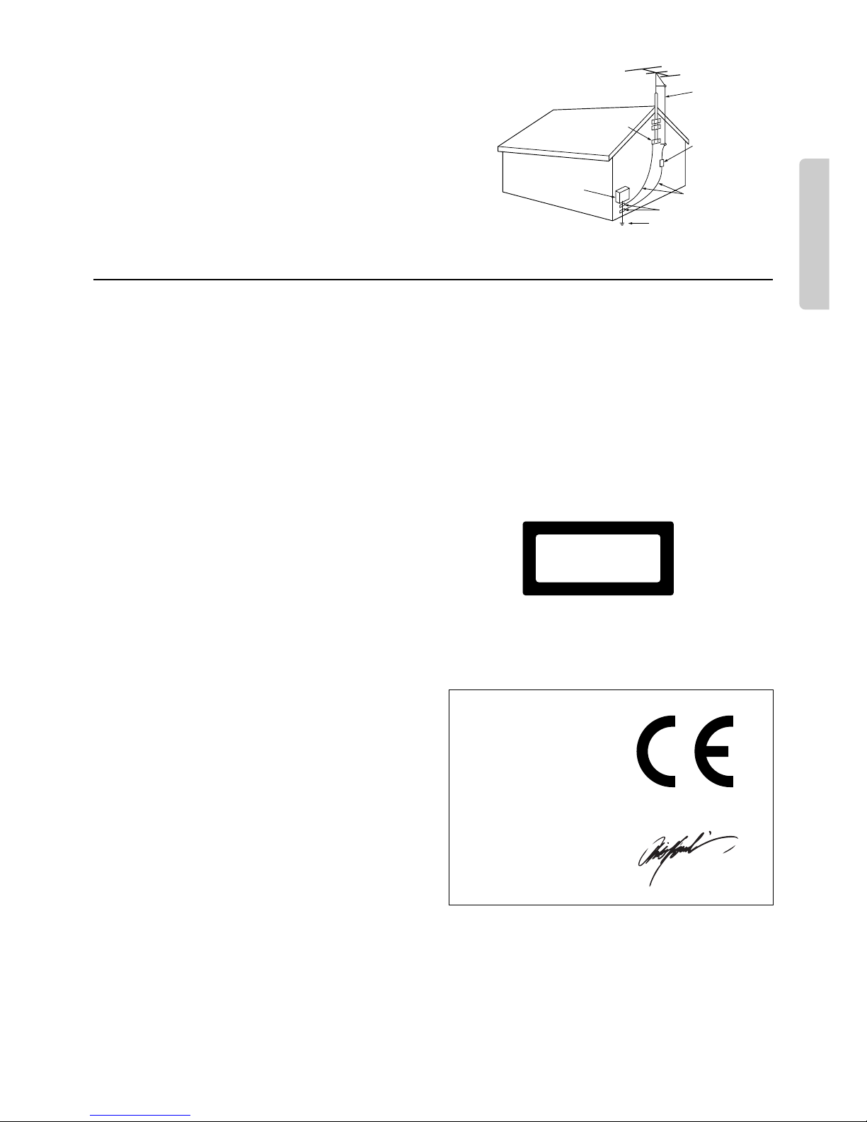
14. Outdoor Antenna Grounding – If an outside antenna or cable
system is connected to the appliance, be sure the antenna or cable
system is grounded so as to provide some protection against volt-
age surges and built-up static charges. Article 810 of the Na-
tional Electrical Code,ANSI/NFPA 70, provides information with
regard to proper grounding of the mast and supporting structure,
grounding of the lead-in wire to an antenna-discharge unit, size
of grounding conductors, location of antenna-discharge unit, con-
nection to grounding electrodes, and requirements for the ground-
ing electrode. See Figure 1.
15. Lightning – For added protection for the appliance during a light-
ning storm, or when it is left unattended and unused for long
periods of time, unplug it from the wall outlet and disconnect
the antenna or cable system. This will prevent damage to the
appliance due to lightning and power-line surges.
16. Power Lines – An outside antenna system should not be located
in the vicinity of overhead power lines or other electric light or
power circuits, or where it can fall into such power lines or cir-
cuits. When installing an outside antenna system, extreme care
should be taken to keep from touching such power lines or cir-
cuits as contact with them might be fatal.
17. Overloading – Do not overload wall outlets, extension cords, or
integral convenience receptacles as this can result in a risk of
fire or electric shock.
18. Object and Liquid Entry – Never push objects of any kind into
the appliance through openings as they may touch dangerous
voltage points or short-out parts that could result in a fire or
electric shock. Never spill liquid of any kind on the appliance.
19. Servicing – Do not attempt to service the appliance yourself as
opening or removing covers may expose you to dangerous volt-
age or other hazards. Refer all servicing to qualified service per-
sonnel.
20. Damage Requiring Service – Unplug the appliance form the
wall outlet and refer servicing to qualified service personnel un-
der the following conditions:
A. When the power-supply cord or plug is damaged,
B. If liquid has been spilled, or objects have fallen into the ap-
pliance,
C. If the appliance has been exposed to rain or water,
D. If the appliance does not operate normally by following the
operating instructions. Adjust only those controls that are
covered by the operating instructions as an improper adjust-
ment of other controls may result in damage and will often
require extensive work by a qualified technician to restore
the appliance to its normal operation,
E. If the appliance has been dropped or damaged in any way,
and
F. When the appliance exhibits a distinct change in performance
– this indicates a need for service.
Important Safeguards
PORTABLE CART WARNING
S3125A
WARNING:
TO REDUCE THE RISK OF FIRE OR ELECTRIC SHOCK,
DO NOT EXPOSE THIS APPLIANCE TO RAIN OR
MOISTURE.
CAUTION:
TO REDUCE THE RISK OF ELECTRIC SHOCK, DO NOT
REMOVE COVER (OR BACK). NO USER-SERVICEABLE
PARTS INSIDE. REFER SERVICING TO QUALIFIED
SERVICE PERSONNEL.
The lightning flash with arrowhead symbol, within an equilateral
triangle, is intended to alert the user to the presence of uninsulated
“dangerous voltage”within the product’s enclosure that may be of
sufficient magnitude to constitute a risk of electric shock to persons.
The exclamation point within an equilateral triangle is intended to
alert the user to the presence of important operating and maintenance
(servicing) instructions in the literature accompanying the appliance.
WARNING
RISK OF ELECTRIC SHOCK
DO NOT OPEN
RISQUE DE CHOC ELECTRIQUE
NE PAS OUVRIR
AVIS

3
21. Replacement Parts –When replacement parts are required, be
sure the service technician has used replacement parts specified
by the manufacturer or have the same characteristics as the origi-
nal part. Unauthorized substitutions may result in fire, electric
shock, or other hazards.
22. Safety Check –Upon completion of any service or repairs to
the appliance, ask the service technician to perform safety checks
to determine that the appliance is in proper operation condition.
23. Wall or Ceiling Mounting –The appliance should be mounted
to a wall or ceiling only as recommended by the manufacturer.
24. Heat –The appliance should be situated away from heat sources
such as radiators, heat registers, stoves, or other appliances (in-
cluding amplifiers) that produce heat.
1. Warranty Claim
You can find the serial number on the rear panel of this unit. In case
of warranty claim, please report this number.
2. Recording Copyright
Recording of copyrighted material for other than personal use is il-
legal without permission of the copyright holder.
3. AC Fuse
The fuse is located inside the chassis and is not user-serviceable. If
power does not come on, contact your Onkyo authorized service
station.
4. Care
From time to time you should wipe the front and rear panels and the
cabinet with a soft cloth. For heavier dirt, dampen a soft cloth in a
weak solution of mild detergent and water, wring it out dry, and
wipe off the dirt. Following this, dry immediately with a clean cloth.
Do not use rough material, thinners, alcohol or other chemical sol-
vents or cloths since these could damage the finish or remove the
panel lettering.
5. Power
WARNING
BEFORE PLUGGING IN THE UNIT FOR THE FIRST TIME,
READ THE FOLLOWING SECTION CAREFULLY.
The voltage of the available power supply differs according to coun-
try or region. Be sure that the power supply voltage of the area where
this unit will be used meets the required voltage (e.g., AC 230 V, 50
Hz or AC 120 V, 60 Hz) written on the rear panel.
Setting the STANDBY button to standby does not shut off the power
completely. So the power cord should be removed from the AC out-
let when the unit is not used for a prolonged time.
6. Do not touch this unit with wet hands
Do not handle this unit or power cord when your hands are wet or
damp. If water or any other liquid enters the case, take this unit to an
authorized service center for inspection.
7. Location of this unit
Place this unit in a well-ventilated location.
Take special care to provide plenty of ventilation on all sides of this
unit especially when it is placed in an audio rack. If ventilation is
blocked, this unit may overheat and malfunction.
Do not expose this unit to direct sunlight or heating units as this
unit's internal temperature may rise and shorten the life of the pickup.
Avoid damp and dusty places and places directly affected by vibra-
tions from the speakers. In particular, avoid placing the unit on or
above one of the speakers.
Be sure this unit is placed in a horizontal position. Never place it on
its side or on a slanted surface as it may malfunction.
Do not place near tuners or TV sets.
If placed next to a TV or tuner, it may cause reception interference
resulting in some noise in the TV or tuner output.
8. Points to remember
If this unit is brought from a cold environment to a warm one or is in
a cold room that is quickly heated, condensation may form on the
pickup, preventing proper operation. In this case, remove the disc
and leave the power ON for about one hour to remove the condensa-
tion.
When transporting this unit, be careful not to bump it.
FIGURE 1:
EXAMPLE OFANTENNA GROUNDINGAS PER NATIONAL ELEC-
TRICAL CODE, ANSI/NFPA 70
Precautions
ANTENNA
DISCHARGE UNIT
(NEC SECTION 810-20)
GROUNDING CONDUCTORS
(NEC SECTION 810-21)
GROUND CLAMPS
POWER SERVICE GROUNDING
ELECTRODE SYSTEM
(NEC ART 250, PART H)
NEC – NATIONAL ELECTRICAL CODE
ELECTRIC
SERVICE
EQUIPMENT
GROUND
CLAMP
ANTENNA
LEAD IN
WIRE
S2898A
Declaration of Conformity
We, ONKYO EUROPE
ELECTRONICS GmbH
INDUSTRIESTRASSE 20
82110 GERMERING,
GERMANY
GERMERING, GERMANY
ONKYO EUROPE ELECTRONICS GmbH
A.HORIUCHI
declare in own responsibility, that the ONKYO product described
in this instruction manual is in compliance with the corresponding
technical standards such as EN60065, EN55013, EN55020 and
EN61000-3-2, -3-3 (or EN60555-2, -3)
This unit contains a semiconductor laser system and is classified as
a “CLASS 1 LASER PRODUCT.”So, to use this model properly,
read this Instruction Manual carefully. In case of any trouble, please
contact the store where you purchased the unit. To prevent being
exposed to the laser beam, do not try to open the enclosure.
DANGER:
INVISIBLE LASER RADIATION WHEN OPEN AND INTER-
LOCK FAILED OR DEFEATED. AVOID DIRECT EXPOSURE
TO BEAM.
CAUTION:
THIS PRODUCT UTILIZES A LASER. USE OF CONTROLS OR
ADJUSTMENTS OR PERFORMANCE OF PROCEDURES
OTHER THAN THOSE SPECIFIED HEREIN MAY RESULT IN
HAZARDOUS RADIATION EXPOSURE.
For European model
This label on the right side of the panel states that:
1. This unit is a CLASS 1 LASER PRODUCT and employs a laser
inside the cabinet.
2. To prevent the laser from being exposed, do not remove the cover.
Refer servicing to qualified personnel.
“CLASS 1 LASER
PRODUCT”

4
■2 ×20 watts min RMS at 4 ohms, 1 kHz no more than
1.0 % THD (FTC rating)
■2 ×20 watts at 4 ohms, 1 kHz, DIN
■2 ×25 watts at 4 ohms, EIAJ
■4-Ohm Drive capability
■High-Grade Discrete Outputs Stage Circuits
■Brushed Aluminium Front Panel
■4-step Acoustic Presence control
■Illuminated Volume knob
■zFull-Function Remote Control
U.S. & Canadian models
■Optical Digital Output
■Subwoofer Preout
■CDR and Tape Inputs/Outputs
European and Asian models
■2 Optical Digital Outputs
■Auto Digital Level Adjustment for Synchro-Recording
(When connected to MD-105X or CDR-205X)
■MD, CDR, and Tape Inputs/Outputs
■RDS (PS) (European models)
Features
For U.S. model
The laser is covered by a housing which prevents exposure during
operation or maintenance. However, this product is classified as a
Laser Product by CDRH (Center for Devices and Radiological
Health) which is a department of the Food and DrugAdministration.
According to their regulations 21 CFR section 1002.30, all manu-
factures who sell Laser Products must maintain records of written
communications between the manufacturer, dealers and customers
concerning radiation safety. If you have any complaints about in-
structions or explanations affecting the use of this product, please
feel free to write to the address on the back page of this manual.
When you write us, please include the model number and serial num-
ber of your unit.
In compliance with Federal Regulations, the certification, identifi-
cation and the period of manufacture are indicated on the rear panel.
FCC Information for User
CAUTION:
The user changes or modifications not expressly approved by the
party responsible for compliance could void the user’s authority to
operate the equipment.
NOTE:
This equipment has been tested and found to comply with the limits
for a Class B digital device, pursuant to Part 15 of the FCC Rules.
These limits are designed to provide reasonable protection against
harmful interference in a residential installation. This equipment gen-
erates, uses and can radiate radio frequency energy and, if not in-
stalled and used in accordance with the instructions, may cause harm-
ful interference to radio communications. However, there is no guar-
antee that interference will not occur in a particular installation. If
this equipment does cause harmful interference to radio or televi-
sion reception, which can be determined by turning the equipment
off and on, the user is encouraged to try to correct the interference
by one or more of the following measures:
•Reorient or relocate the receiving antenna.
•Increase the separation between the equipment and receiver.
•Connect the equipment into an outlet on a circuit different from
that to which the receiver is connected.
•Consult the dealer or an experienced radio/TV technician for help.
Note to CATV system installer:
This reminder is provided to call the CATV system installer’s atten-
tion to Article 820-40 of the NEC, ANSI/NFPA 70, which provides
guidelines for proper grounding and, in particular, specifies that the
cable ground shall be connected to the grounding system of the build-
ing, as close to the point of cable entry as practical.
For Canadian model
NOTE: THIS CLASS B DIGITAL APPARATUS COMPLIES
WITH CANADIAN ICES-003.
For models having a power cord with a polarized plug:
CAUTION: TO PREVENT ELECTRIC SHOCK, MATCH WIDE
BLADE OF PLUG TO WIDE SLOT, FULLY INSERT.
Modele pour les Canadien
REMARQUE: CETAPPAREIL NUMÉRIQUE DE LA CLASSE
B EST CON-FORME ÀLA NORME NMB-003 DU CANADA.
Sur les modèles dont la fiche est polarisée:
ATTENTION: POUR ÉVITER LES CHOCS ÉLECTRIQUES,
INTRODUIRE LA LAME LA PLUS LARGE DE LA FICHE DANS
LA BORNE CORRESPONDANTE DE LA PRISE ET POUSSER
JUSQU’AU FOND.
For British model
Replacement and mounting of an AC plug on the power supply cord
of this unit should be performed only by qualified service personnel.
IMPORTANT
The wires in the mains lead are coloured in accordance with the
following code:
Blue : Neutral
Brown : Live
As the colours of the wires in the mains lead of this apparatus may
not correspond with the coloured markings identifying the terminals
in your plug, proceed as follows:
The wire which is coloured blue must be connected to the terminal
Memory Preservation
This unit does not require memory preservation batteries.A built-
in memory power back-up system preserves the contents of the
memory during power failures and even when the unit is un-
plugged. The unit must be plugged in order to charge the back-up
system.
The memory preservation period after the unit has been unplugged
varies depending on climate and placement of the unit. On the
average, memory contents are protected over a period of a few
weeks after the last time the unit has been unplugged. This pe-
riod is shorter when the unit is exposed to a highly humid cli-
mate.
which is marked with the letter N or coloured black.
The wire which is coloured brown must be connected to the termi-
nal which is marked with the letter L or coloured red.
IMPORTANT
A 5 ampere fuse is fitted in this plug. Should the fuse need to be
replaced, please ensure that the replacement fuse has a rating of 5
amps and that it is approved by ASTA or BSI to BS1362. Check for
the ASTA mark or the BSI mark on the body of the fuse.
IF THE FITTED MOULDED PLUG IS UNSUITABLE FOR THE
SOCKET OUTLET INYOUR HOME THEN THE FUSE SHOULD
BE REMOVED AND THE PLUG CUT OFF AND DISPOSED OF
SAFELY. THERE IS A DANGER OF SEVERE ELECTRICAL
SHOCK IF THE CUT OFF PLUG IS INSERTED INTO ANY 13
AMP SOCKET.
If in any doubt, please consult a qualified electrician.

5
Installing the remote controller batteries
1. Remove the battery compartment cover by pressing and sliding it
out.
2. Insert twoAA (R6- or UM-3)-size batteries into the battery com-
partment. Carefully follow the polarity diagram (positive (+) and
negative (–) symbols) inside the battery compartment.
3. After batteries are installed and seated correctly, replace the com-
partment cover.
Notes
•Do not mix new batteries with old batteries or different kinds of
batteries.
•To avoid corrosion, remove the batteries if the remote controller
is not to be used for a long time.
•Remove dead batteries immediately to avoid damage from cor-
rosion. If the remote controller doesn’t operate smoothly, replace
both the batteries at the same time.
Using the remote controller
Point the remote controller toward the remote control sensor.
Notes
•Place the unit away from strong light such as direct sunlight or
inverted fluorescent light which can prevent proper operation of
the remote controller.
•Using another remote controller of the same type in the same
room or using the unit near equipment which uses infrared rays
may cause operational interference.
•Do not put any object such as a book on the remote controller.
The buttons of the remote controller may be pressed by mistake
and drain the batteries.
•Make sure the audio rack doors do not have colored glass. Plac-
ing the unit behind such doors may prevent proper remote con-
troller operation.
•If there is any obstacle between the remote controller and the
remote control sensor, the remote controller will not operate.
Before operating this unit
Remote
control sensor
CR-305X
approx. 5 m
(16 feet)
30°
30°
1
2
3
Supplied accessories
Check that the following accessories are supplied with this unit.
AM loop antenna ×1 FM indoor antenna ×1
Remote controller (RC-421S) ×1
Batteries (size AA or UM-3) ×2
75/300 ohms antenna adapter ×1
REMOTE CONTROLLER
RC-421S
The following accessory is available on the models other than U.S.
and Canadian models.

6
Audio equipment connections
•Do not connect the AC power cord (mains lead) to the wall outlet (the mains) until you have completed all the other connections
including the zconnections on page 7, and the speaker connections on page 8.
•On each pair of connectors, a red connector (marked R) corresponds to the right channel, and a white connector (marked L) to the left
channel. Connect white plugs of audio connection cables to L connectors and connect red plugs of audio connection cables to R
connectors .
•Please refer to the instruction manual for each component when you make any connec-
tions.
•Insert the plug securely. If the connection is incomplete, noise or malfunction may result.
U.S. and Canadian models
Asian and European models
To L connector ,(White)
To R connector ,(Red)
Audio connection cable
(White) / To L connector
(Red) / To R connector
Improper connection
Insert completely
L
RL
RL
REMOTE
CONTROL
OPTICAL
SPEAKERS
TAPE
CDR
DIGITAL
OUTPUT
SUBWOOFER
PRE OUT
ANTENNA AM
FM
75
R
OUT
(REC)
(PLAY)
IN
OUT
(REC)
(PLAY)
IN
L
1
2
RL
RL
REMOTE
CONTROL
OPTICAL
SPEAKERS
TAPE
CDR MD
ANTENNA AM
FM
75
DIGITAL
OUTPUT
R
OUT
(REC)
(PLAY)
IN
OUT
(REC)
(PLAY)
IN
OUT
(REC)
(PLAY)
IN
RL
Stereo cassette
tape deck
CD recorder
MD recorder
Stereo cassette
tape deck
CD recorder
INPUT (REC)
OUTPUT (PLAY)
INPUT (REC)
OUTPUT (PLAY)
DIGITAL OPTICAL INPUT
: Signal flow
INPUT (REC)
OUTPUT (PLAY)
INPUT (REC)
OUTPUT (PLAY)
DIGITAL OPTICAL INPUT
OUTPUT
(PLAY)
: Signal flow
INPUT
(REC)
DIGITAL OPTICAL
INPUT
To wall outlet
To wall outlet
Protective cap for the optical digital audio connector
•Remove the protective cap before you use
the OPTICAL DIGITAL OUTPUT con-
nector. Please retain it for future use. If
you do not use the optical digital audio
connector, make sure to replace the cap.

7
Audio equipment connections
zremote control cable (supplied with every
ONKYO component that has zconnectors ex-
cept for the amplifier and receiver)
This unit
(CR-305X)
MD recorder
Stereo cassette
tape deck
CD recorder
Connecting the zremote control cables
If your other components are made by ONKYO and those components are equipped with zconnectors, you can control the z-
connected components with the supplied remote controller.
•The unit must be connected in the zsystem hookups for zcontrol operations.
•Each component has two zconnectors except for this unit. There is no difference between these connectors.
•The components may be connected in any order.
•The hookups on the previous page are necessary independently of the zsystem hookups.
•The illustration below is an example of a zhookup.
Note
•This is not an example of stacking the components.
What can you do with the other ONKYO components by connecting with an zremote control cables?
Combination use of the unit with the stereo cassette tape deck K-505X, CD recorder CDR-205X (not available in U.S. and Canada), or MD
recorder MD-105X (not available in U.S. and Canada) enables you to operate the following convenient functions.
•Remote control of the components
All the components can be operated using the supplied remote controller. (Refer to “Using the remote controller” on page 35.)
•Program timer
You can operate timer playback and recording using this unit. (With the CD recorder CDR-205X, you can operate timer playback only.)
(Refer to “Using the timer” on page 26.)
•CD dubbing
Simple CD dubbing using the CD recorder, MD recorder, or stereo cassette tape deck is possible with the pressing of a single button.
The unit begins a search for the peak level and the CD recorder, MD recorder, or stereo cassette tape deck sets the optimum recording level
to match that peak level. (Refer to CDR-205X, MD-105X, or K-505X instruction manual for details.)
•CD synchro recording
With the CD recorder, MD recorder, or stereo cassette tape deck in recording pause, starting CD playback causes these components to start
recording. (Refer to CDR-205X, MD-105X, or K-505X instruction manual for details.)
Note
•Make sure the unit and each component are firmly connected with the zremote control cable, audio connection cable, and optical fiber
cable. If the connection is incomplete, the above functions does not work.
About the OPTICAL DIGITAL OUTPUT connector
•An optical digital audio input equipped MD recorder, DAT, or CD recorder may be connected with an optical fiber audio cable for digital
recording of this unit.

8
Connecting speaker systems
Connecting left and right speakers
•The load impedance of each speaker must be at least 4 ohms.
•Do not use unnecessarily long or extremely thin speaker cords. Otherwise, the DC resistance of the speaker cords may become too
high, lowering the damping factor and causing the sound quality to deteriorate.
•Do not connect the speaker cord to the L and R connectors at the same time and do not connect two or more speakers to the same
speaker connectors.
Connecting the speaker cords to the speaker connectors
1. Strip 15 mm from the
end of each cord.
2. Twist the stripped end
of the cord.
Note
To prevent damage to circuits never
short-circuit the positive (+) and
negative (-) speaker wires.
3. Press down the lever. The
wire of the stripped end
of the cord should appear
slightly.
NO
NO NO
15mm (5/8”)
RL
SPEAKERS RL
SPEAKERS
RL
SPEAKERS
–+–+
1. Push the lever up.
2. Insert the stripped end of
the cord.
Preparing the speaker cords for connection

9
V
O
L
U
M
E
U
P
V
O
L
U
M
E
D
O
W
N
REMOTE CONTROLLER
STANDBY/ON
INPUT
TIMER ENTER
RANDOM
MEMORY REPEAT
CD
PLAY MODE
SLEEP
A.PRESENCE
CLOCK
CALL
MUTING
REPEAT
MD
VOLUME
PLAY MODE
REPEAT
TUNER
PRESET
CDR
TAPE
SCROLL
RC-421S
Connecting speaker systems
Connecting a sub-woofer (U.S. and Canadian models)
•The SUBWOOFER PRE OUT jack supplies the left and right mixed monaural signals to the sub-woofer.
Connecting the AC power cord (mains lead)
1. Connect the AC power cord (mains lead) to the wall outlet
(the mains).
“– –:––” appears on the display.
2. Press the STANDBY/ON button.
Notes
•If the AC power cord (mains lead) is connected to the AC outlet
of another component, that component's AC power cord (mains
lead) must be connected to the wall outlet (the mains) to supply
power to the unit. If the component has a power switch, it must be
set to On.
•If you do not use the unit for a long time, remove the power cord
of the CR-305X from the AC outlet.
•The unit may cause a power surge on your home circuit when you
turn it on. If this interferes with any other devices connected to
the same circuit, plug this unit into another outlet on a separate
circuit.
1. To wall outlet
2. STANDBY/ON
2. STANDBY/ON
DISPLAY
TUNING/PRESET
STANDBY/ON
MEMORY FM MODE
CLEAR
PHONES
INPUT
M
A
X
M
I
N
A
C
O
U
S
T
I
C
P
R
E
S
E
N
C
E
V
O
L
U
M
E
L
RL
RL
REMOTE
CONTROL
OPTICAL
SPEAKERS
TAPE
CDR
DIGITAL
OUTPUT
SUBWOOFER
PRE OUT
ANTENNA AM
FM
75
R
OUT
(REC)
(PLAY)
IN
OUT
(REC)
(PLAY)
IN
Active sub-woofer

10
Making antenna connections
Assembling the AM loop antenna
Assemble the loop antenna as shown in the illustration.
Connecting the antenna cable
1. Press down the lever.
2. Insert the wire into the hole.
3. Release the lever to replace it.
Insert into the hole.
12 3
Connecting the included antennas
Connecting the FM indoor antenna
The FM indoor antenna is for indoor use only. Extend the antenna
and move it in various directions until the clearest signal is received.
Fix it with push pins or similar implements in the position that will
cause the least amount of distortion.
If the reception is not very clear with the attached FM indoor an-
tenna, the use of an outdoor antenna is recommended.
U.S. and Canadian models
Remove the insulation at the tip of the cable, and insert the cable
securely, fully to the end of the exposed tip.
Connecting the AM loop antenna
The AM loop antenna is for indoor use only. Set it in the direction
and position where you receive the clearest sound. Put it as far away
as possible from the unit, TVs, speaker cables, and power cords.
When reception is not satisfactory with the attached AM loop an-
tenna alone, connection of an outdoor antenna is recommended.
U.S. and Canadian models
Asian and
European models
ANTENNA AM
FM
75
ANTENNA AM
FM
75

11
Making antenna connections
Connecting an AM outdoor antenna
The outdoor antenna will be more effective if it is stretched horizon-
tally above a window or outside.
•Do not remove the AM loop antenna.
•To avoid the risk of lightning and electrical shock, grounding is
necessary. Follow item 14 of the “Important Safeguards”on page
2 when you install the outdoor antenna.
ANTENNA AM
FM
75
Directional Iinkage
Do not use the same antenna for both FM and TV (or VCR) recep-
tion since the FM and TV (or VCR) signals can interfere with each
other. If you must use a common FM/TV (or VCR) antenna, use a
directional linkage type splitter.
Directional lingake
type splitter
To CR-305X To TV (or VCR)
Connecting the antenna cable to the 75/300 ohm
antenna adapter (Asian models)
Connecting the 300 ohm ribbon wire
Loosen the screws and wrap the wire around these screws. Then
tighten the screws with a screwdriver.
Connecting the coaxial cable
1. With your fingernail or a small screwdriver, press the stoppers
outward and remove the cover.
2. Remove the transformer wire A from slit B and insert it into slit
C.
3. Prepare the coaxial cable as shown in the diagram.
Connect the 75/300 ohm antenna adapter to the coaxial cable.
1 Insert the end of the cable.
2Clamp it in place with pliers.
4. Re-install the cover.
12 3
Outdoor
antenna
Indoor
antenna
300 ohms
ribbon wire
Slit B
6
mm
3
mm
6
mm
Wire A
Slit C
15 mm
1
2
Connecting an FM outdoor antenna
Please make sure that you follow the considerations below regard-
ing the location.
Keep the antenna away from noise sources (neon signs, busy roads,
etc.).
It is dangerous to put the antenna close to power lines. Keep it well
away from power lines, transformers, etc.
•To avoid the risk of lightning and electrical shock, grounding is
necessary. Follow item 14 of the “Important Safeguards”on page
2 when you install the outdoor antenna.
ANTENNA AM
FM
75
ANTENNA AM
FM
75
U.S., Canadian, and European models
Asian models

12
Control positions and names
DISPLAY
TUNING/PRESET
STANDBY/ON
MEMORY FM MODE
CLEAR
PHONES
A
C
O
U
S
T
I
C
P
R
E
S
E
N
C
E
INPUT
A
C
O
U
S
T
I
C
P
R
E
S
E
N
C
E
V
O
L
U
M
E
M
A
X
M
I
N
ST
S.BASS
DIRECT
STEREO
MUTING
MIN
kHz
MHz
MONOAUTOTRACKTIMER
W.DAY
W.END
REC
SLEEP
CD
MEMORY
REPEAT
RANDOM
RDS
PMAM
123 4 5 6 789
10
11121315
abcde f g h i j k l
mnopqr
Front panel
For more information about buttons or knobs, refer to the pages listed
in the brackets ( [ ] ) below.
1. STANDBY/ON button [9, 28, 30]
2. MEMORY button [20, 22 to 24]
3. FM MODE button [24]
4. DISPLAY button [21, 25]
5. INPUT a/sbuttons [16, 18, 22 to 24]
6. TUNING/PRESET a/sbuttons [22 to 24]
q/d, f/w buttons [18, 20]
7. r button [18, 20]
8. ebutton [18, 20]
9. n button [16, 18, 20]
10. ACOUSTIC PRESENCE button and indicator [16]
11. VOLUME control knob [16]
12. Remote contrtol sensor [5]
13. Display (Refer to the “Display” illustration.)
14. Disc tray [18]
15. PHONES jack [17]
Display
If a protective film on the surface of the screen making it difficult to
read the display, remove the film.
a. CD indicator
b. MEMORY indicator
c. (play/pause) indicator
d. TRACK indicator
e. AUTO indicator
f. MONO indicator
g. AM/PM indicator
AM or PM lights up when you switch the clock setting to “12H”
(12 hour display).
h. RDS indicator (European models only)
i. Single remaining time indicator
j. Total remaining time indicator
k. Tuning indicator
l. STEREO indicator
m. MUTING indicator
n. Frequency indicators
o. Sleep time indicator
p. Multi display
q. REPEAT indicator
r. RANDOM indicator
s. Timer setting indicators
Display
s
14

13
Remote controller RC-421S
V
O
L
U
M
E
U
P
V
O
L
U
M
E
D
O
W
N
REMOTE CONTROLLER
STANDBY/ON
INPUT
TIMER ENTER
RANDOM
MEMORY REPEAT
CD
PLAY MODE
SLEEP
A.PRESENCE
CLOCK
CALL
MUTING
REPEAT
MD
VOLUME
PLAY MODE
REPEAT
TUNER
PRESET
CDR
TAPE
SCROLL
RC-421S
1
2
3
4
5
6
7
8
9
10
11
12
13
For more information about buttons or knobs, refer to the pages listed
in the brackets ( [ ] ) below.
1. STANDBY/ON button [9]
Toggles between STANDBY and ON.
2. TIMER operation buttons [14, 15, 26 to 30]
Enables you to make the settings of the clock, timer playback
and recording.
3. CD operation buttons [16, 18 to 20]
4. MD operation buttons [35]
5. SLEEP button [31]
Enables you to make the sleep time setting.
6. VOLUME y(UP)/u(DOWN) buttons [16, 17]
Enables you to increase or decrease the volume level.
7. CLOCK CALL button [15]
Enables you to display the current time.
8. CDR operation buttons [35]
9. TUNER PRESET u/ybuttons [24]
Enables you to select the PRESET stations.
10. INPUT u/ybuttons [16, 18, 22 to 24]
Enables you to select a listening source.
11. A. PRESENCE button [16]
Enables you to switch acoustic presence off and types.
12. MUTING button [17]
Enables you to mute the sound temporarily.
13. TAPE operation buttons [35]

14
3
4
ENTER
1
2
Setting the clock
Setting the clock
1. Press the TIMER button until “ADJUST” is selected on the
display, then press the ENTER button.
The day of the week will flash on the display.
2. Press the u/ybuttons until the desired day of the week is
selected, then press the ENTER button.
The time will flash on the display.
3. Use the u/ybuttons to set the desired time.
4. Press the ENTER button.
The clock will start operating. When you set the clock while the
unit is in the standby mode, the present time will continue to be
displayed. When you set the clock while the unit is on, the nor-
mal display will be resumed.
TIMER ENTER
u/y
V
O
L
U
M
E
U
P
V
O
L
U
M
E
D
O
W
N
REMOTE CONTROLLER
STANDBY/ON
INPUT
TIMER ENTER
RANDOM
MEMORY REPEAT
CD
PLAY MODE
SLEEP
A.PRESENCE
CLOCK
CALL
MUTING
REPEAT
MD
VOLUME
PLAY MODE
REPEAT
TUNER
PRESET
CDR
TAPE
SCROLL
RC-421S
TIMER
ENTER
ENTER

15
Clock Call function
Press the CLOCK CALL button to display the time, press again to
cancel the time display.
Note
•If the time has not been set, “ADJUST” will flash on the display.
In this case, press again the CLOCK CALL button, then set the
clock. (Refer to “Setting the clock” on page 14.)
CLOCK CALL
Setting the clock
TIMER ENTER
u/y
V
O
L
U
M
E
U
P
V
O
L
U
M
E
D
O
W
N
REMOTE CONTROLLER
STANDBY/ON
INPUT
TIMER ENTER
RANDOM
MEMORY REPEAT
CD
PLAY MODE
SLEEP
A.PRESENCE
CLOCK
CALL
MUTING
REPEAT
MD
VOLUME
PLAY MODE
REPEAT
TUNER
PRESET
CDR
TAPE
SCROLL
RC-421S
CLOCK
CALL
Switching between the 24 hour and 12 hour
display settings
1. Press the TIMER button repeatedly to display “24H/12H.”
2. Press the ENTER button.
“24H” or “12H” flashes on the display.
3. Use the u/ybuttons to select 24H (24 hour display) or 12H
(12 hour display).
4. Press the ENTER button to confirm the setting.
1
2
3
4
TIMER
ENTER
ENTER

16
Choosing the required source
1
3
Choosing the required source
1. Press the INPUT a/sbuttons or the INPUT u/ybuttons
on the remote controller to select the desired source.
Each time you press these buttons, the display changes as fol-
lows.
U.S. and Canadian models: CD, CDR, TAPE, FM or AM
Asian and European models:
CD, MD, CDR, TAPE, FM or AM
2. Start playing the source you selected in step 1.
The example shown on the left indicates that you have selected
the CD as the source.
3. Set the volume to appropriate level using the VOLUME con-
trol or the VOLUME y(UP)/u(DOWN) buttons on the re-
mote controller.
Turn the VOLUME control clockwise to increase the volume or
counterclockwise to decrease the volume.
INPUT u/y
V
O
L
U
M
E
U
P
V
O
L
U
M
E
D
O
W
N
REMOTE CONTROLLER
STANDBY/ON
INPUT
TIMER ENTER
RANDOM
MEMORY REPEAT
CD
PLAY MODE
SLEEP
A.PRESENCE
CLOCK
CALL
MUTING
REPEAT
MD
VOLUME
PLAY MODE
REPEAT
TUNER
PRESET
CDR
TAPE
SCROLL
RC-421S
DISPLAY
TUNING/PRESET
STANDBY/ON
MEMORY FM MODE
CLEAR
PHONES
INPUT
M
A
X
M
I
N
A
C
O
U
S
T
I
C
P
R
E
S
E
N
C
E
V
O
L
U
M
E
INPUT a/s
VOLUME
VOLUME
y/u
INPUT
INPUT
Remote controller
V
O
L
U
M
E
M
A
X
M
I
N
V
O
L
U
M
E
U
P
V
O
L
U
M
E
D
O
W
N
VOLUME
Remote controller
2Remote controller
TRACK
CD
s
n
ACOUSTIC PRESENCE
Acoustic Presence reinforces super bass, bass and treble of the mu-
sic through the use of exclusive Onkyo circuitry. You can enjoy the
powerful sound with the following 4 presence settings.
Each press of the ACOUSTIC PRESENCE button or the A. PRES-
ENCE button on the remote controller changes the mode as follows,
and the indicator lights up while you are activating Acoustic Pres-
ence.
A. PR-OFF: Acoustic Presence is off.
A. PR-1: Super bass is reinforced.
A. PR-2: Bass is reinforced.
A. PR-3: Super bass and bass are reinforced at the same time.
A. PR-4: Treble is reinforced in addition to super bass and
bass that are reinforced in the A. PR-3 mode.
A.PRESENCE
Remote controller
ACOUSTIC
PRESENCE
A. PRESENCE
Adjusting the sound
A. PR-OFF A. PR-1 A. PR-2
A. PR-3A. PR-4
Indicator
A
C
O
U
S
T
I
C
P
R
E
S
E
N
C
E

17
Muting / Listening with the headphones
Listening with the headphones
Connect the stereo headphones mini plug to the PHONES jack.
The speakers will reproduce no sound while the headphones are con-
nected.
Tip
•You can adjust the sound through the headphones as well as
through the speakers. See “Adjusting the sound”on the previous
page for operations.
Muting the sound
Press the MUTING button on the remote controller to mute the sound.
The MUTING indicator flashes on the display. To restore the sound,
press the MUTING button again.
Tip
During muting,
•if you press the VOLUME y(UP)/u(DOWN) buttons on the
remote controller, the MUTING indicator disappears then the
sound will be restored, and
•if you turn the unit in Standby mode, and turn it on again, the
MUTING indicator disappears.
MUTING
V
O
L
U
M
E
U
P
V
O
L
U
M
E
D
O
W
N
REMOTE CONTROLLER
STANDBY/ON
INPUT
TIMER ENTER
RANDOM
MEMORY REPEAT
CD
PLAY MODE
SLEEP
A.PRESENCE
CLOCK
CALL
MUTING
REPEAT
MD
VOLUME
PLAY MODE
REPEAT
TUNER
PRESET
CDR
TAPE
SCROLL
RC-421S
DISPLAY
TUNING/PRESET
STANDBY/ON
MEMORY FM MODE
CLEAR
PHONES
INPUT
M
A
X
M
I
N
A
C
O
U
S
T
I
C
P
R
E
S
E
N
C
E
V
O
L
U
M
E
MUTING
MUTING
PHONES
VOLUME
y/u
STANDBY/ON
MEMORY FM MODE
CLEAR
PHONES

18
Playing a CD
1
2
3
INPUT u/y
V
O
L
U
M
E
U
P
V
O
L
U
M
E
D
O
W
N
REMOTE CONTROLLER
STANDBY/ON
INPUT
TIMER ENTER
RANDOM
MEMORY REPEAT
CD
PLAY MODE
SLEEP
A.PRESENCE
CLOCK
CALL
MUTING
REPEAT
MD
VOLUME
PLAY MODE
REPEAT
TUNER
PRESET
CDR
TAPE
SCROLL
RC-421S
DISPLAY
TUNING/PRESET
STANDBY/ON
MEMORY FM MODE
CLEAR
PHONES
INPUT
M
A
X
M
I
N
A
C
O
U
S
T
I
C
P
R
E
S
E
N
C
E
V
O
L
U
M
E
INPUT a/s
INPUT
INPUT
Remote controller
TRACK
CD
Remote controller
rn
s
Label side
e
eg
Locating a particular point of the track
Press and hold the f/w button for fast forwarding, or the
q/d button for fast reversing during playback or pause until
you find the point you want.
Selecting the track to play
To locate the beginning of the playing track, press the q/d
button or the qbutton on the remote controller. To select the
former track in reverse order, press the q/d button or the
qbutton on the remote controller. To select the next track in
order, press the f/w button or the wbutton on the remote
controller.
If you have selected the track while the CD is stopped, press the
nbutton or the sbutton on the remote controller to start play-
back.
Note
•It may take a while to start playing back CDs with many tracks.
q/d, f/w
q, w
Playing a CD
1. Press the rbutton to open the disc tray, and put the CD in
the tray with the label side facing up. Put 8-cm discs within
the center circle of the tray.
To close the disc tray, press the rbutton.
2. Press the INPUT a/sbuttons or the INPUT u/y buttons
on the remote controller to switch the input source to CD.
The CD indicator lights up on the display.
3. Press the n button or the sbutton on the remote con-
troller to start playback.
•Playback automatically stops when the last track has been played.
•If the unit is in Standby mode and there is a CD in the disc tray, it
tuns on automatically and starts playback even if another source
is selected when the n button is pressed.
•If you switch the input source to FM or AM during playback, the
unit pauses playback of the CD for as long as FM or AM is se-
lected. To resume playback of the CD, switch the input source
back to CD, then press the n button or the sbutton on the
remote controller.
To stop playback,
•Press the ebutton.
To pause,
•Press the n button or the g button on the remote controller.
The indicator lights up on the display.
•To restart playback, press the n button or the sbutton on
the remote controller. Playback starts again from exactly where
it left off.

19
Playing a CD
RANDOM playback (remote controller only)
All the tracks on the disc will be shuffled, then played back.
To start RANDOM playback, press the RANDOM button while the
CD is stopped, or press the RANDOM button during playback.
•When the unit finishes playing the last track, playback will be
repeated with a different track order.
•You can combine the RANDOM mode with the MEMORY mode.
In this case, the programmed tracks are played back in random
order. (Refer to “MEMORY playback”on page 20.)
To cancel RANDOM playback,
•press the RANDOM button again. The RANDOM indicator dis-
appears.
RANDOM
REPEAT
V
O
L
U
M
E
U
P
V
O
L
U
M
E
D
O
W
N
REMOTE CONTROLLER
STANDBY/ON
INPUT
TIMER ENTER
RANDOM
MEMORY REPEAT
CD
PLAY MODE
SLEEP
A.PRESENCE
CLOCK
CALL
MUTING
REPEAT
MD
VOLUME
PLAY MODE
REPEAT
TUNER
PRESET
CDR
TAPE
SCROLL
RC-421S
s
RANDOM
REPEAT
T
TRACK
CD
MEMORY
RANDOM
T
TRACK
CD
MEMORY
REPEAT
REPEAT playback (remote controller only)
The REPEAT mode plays back a CD repeatedly.
Press the REPEAT button and then press the sbutton, or press the
REPEAT button during playback.
•You can combine the REPEAT mode with the MEMORY mode.
In this case, the programmed tracks are played back repeatedly.
(Refer to “MEMORY playback”on page 20.)
To cancel REPEAT playback,
•press the REPEAT button again. The REPEAT indicator disap-
pears.

20
MEMORY
MEMORY
Playing a CD
q, w
V
O
L
U
M
E
U
P
V
O
L
U
M
E
D
O
W
N
REMOTE CONTROLLER
STANDBY/ON
INPUT
TIMER ENTER
RANDOM
MEMORY REPEAT
CD
PLAY MODE
SLEEP
A.PRESENCE
CLOCK
CALL
MUTING
REPEAT
MD
VOLUME
PLAY MODE
REPEAT
TUNER
PRESET
CDR
TAPE
SCROLL
RC-421S
DISPLAY
TUNING/PRESET
STANDBY/ON
MEMORY FM MODE
CLEAR
PHONES
INPUT
M
A
X
M
I
N
A
C
O
U
S
T
I
C
P
R
E
S
E
N
C
E
V
O
L
U
M
E
s
n
q/d, f/w
e
erDISPLAY
1
2
3
MEMORY playback
You can select and store track numbers (up to 20) in the desired
playback order.
1. Press the MEMORY button while the CD is stopped.
2. Press the q/d, f/w buttons to select the first
track you would like to play back, then press the MEMORY
button.
•To select the next track to be played, repeat this step.
3. Press the nbutton to start MEMORY playback.
•When the unit finishes playing the track which number you stored
last, playback stops. The track numbers stored in memory will be
retained.
Remote controller operation
1. Press the MEMORY button while the CD is stopped.
2. Press the q, wbuttons to select the first track you would
like to play back, then press the MEMORY button.
•To select the next track to be played, repeat this step.
3. Press the sbutton to start MEMORY playback.
•When the unit finishes playing the track which number you stored
last, playback stops. The track numbers stored in memory will be
retained.
Notes
•If you try to store more than 20 tracks into memory, “FULL”
flashes on the display to indicate that the memory is full.
•If the MEMORY button is pressed during playback, the playing
track is stored into memory.
To stop MEMORY playback,
•press the ebutton during MEMORY playback.
To cancel MEMORY playback mode,
•press the MEMORY button. The MEMORY indicator disappears.
To erase a track number from memory,
•while in MEMORY playback mode, and the CD is stopped, press
the ebutton. Each press erases the last track number from
memory.
To erase all track numbers from memory,
•while in MEMORY playback mode, and the CD is stopped, press
the rbutton.
T
TRACK
CD
MEMORY
MEMORY FM MODE
CLEAR
MEMORY
Remote controller
TRACK
CD
MEMORY
Remote controller
TRACK
CD
MEMORY
Remote controller
TUNING/PRESET
MEMORY FM MODE
CLEAR
T
TRACK
CD
MEMORY
MEMORY
Remote controller
T
TRACK
CD
MEMORY
Other manuals for CR-305X
1
Table of contents
Other Onkyo Car Receiver manuals

Onkyo
Onkyo T-407 User manual

Onkyo
Onkyo CR-535 User manual

Onkyo
Onkyo CS-375D User manual

Onkyo
Onkyo CR-245DAB User manual

Onkyo
Onkyo C-701A User manual

Onkyo
Onkyo CR-505DAB User manual

Onkyo
Onkyo CR-325UKD User manual

Onkyo
Onkyo CR-505DA User manual

Onkyo
Onkyo CR-545 User manual

Onkyo
Onkyo CS-345 User manual