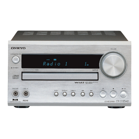
Onkyo CR-185X User manual

1
CD RECEIVER
VOLUME
TUNER CD/LINE TAPE/MD MIN MAX
SYSTEM PHONES
STAND-BY/ ON AUTO / MONO
DISPLAYMEMORY
TUNING / PRESET
CR-185X
CR-185X
Features................................................ 2
Important safeguards ........................... 3
Special cautions for CD player............ 4
Precautions .......................................... 5
Before operation this unit .................... 5
System connections ............................. 6
Control Positions and Names ............ 10
Setting the Time and Day .................. 12
Operating the Amplifier..................... 13
Listen to the Radio............................. 15
Receiving RDS .................................. 18
Playing CDs....................................... 19
Using the Timer ................................. 24
Handling CDs .................................... 29
Troubleshooting Guide ...................... 30
Specifications..................................... 31
CONTENTS
CD Receiver
Instruction Manual

2
ATTENTION FOR BRITISH MODEL
Replacementand mountingof anAC plugon thepower supplycord
ofthisunitshouldbeperformedonlybyqualifiedservicepersonnel.
IMPORTANT:
The wires in the mains lead are coloured in accordance with the
following code:
Blue: Neutral
Brown: Live
As the colours of the wires in the mains lead of this appliance may
notcorrespondwiththecolouredmarkingsidentifyingtheterminals
in your plug, proceed as follows:
ThewirewhichiscolouredBLUEmustbeconnectedtotheterminal
in the plug which is marked with the letter N or coloured BLACK.
The wire which is coloured BROWN must be connected to the
terminal in the plug which is marked with the letter L or coloured
RED.
IMPORTANT
A5ampfuseisfittedin thisplug.Shoudthe fuseneedtobe replaced
please ensure that the replacement fuse has a rating of 5 amps and
thatitisapprovedbyASTAorBSI toBS1362.Check fortheASTA
mark or the BSI mark on the body of the fuse.
IF THE FITTED MOULDED PLUG IS UNSUITABLE FOR THE
SOCKETOUTLETINYOURHOMETHENTHEFUSESHOULD
BEREMOVEDAND THEPLUGCUTOFFANDDISPOSEDOF
SAFELY. THERE IS A DANGER OF SEVERE ELECTRICAL
SHOCK IF THE CUT OFF PLUG IS INSERTED INTO ANY 13
AMP SOCKET.
If in any doubt please consult a qualified electrician.
Declaration of Conformity
We, ONKYO EUROPE
ELECTRONICS GmbH
INDUSTRIESTRASSE 20
82110 GERMERING,
GERMANY
declare in own responsibility, that the ONKYO product described
in this instruction manual is in compliance with the corresponding
technical standards such as EN55013, EN55020, EN61000-3-2, -3-3
and EN60065
GERMERING, GERMANY
ONKYO EUROPE ELECTRONICS GmbH
K.OTSU
FOR U.S.A. MODEL
Note to CATV system installer:
●This reminder is provided to call the CATV system installer’s
attention to Section 820-40 of the NEC which provides guide-
lines for proper grounding and, in particular, specifies that the
cable ground shall be connected to the grounding system of the
building, as close to the point of cable entry as practical.
FOR CANADIAN MODEL
POUR LE MODELE CANADIEN
●For models having a power cord with a polarized plug.
CAUTION: TO PREVENT ELECTRIC SHOCK, MATCH
WIDE BLADE OF PLUG TO WIDE SLOT, FULLY INSERT.
●Sur les modèles dont la fiche est polarisée.
ATTENTION: POUR ÉVITER LES CHOCS ÉLECTRI-
QUES, INTRODUIRE LA LAME LA PLUS LARGE DE LA
FICHE DANS LA BORNE CORRESPONDANTE DE LA PRISE
ET POUSSER JUSQU’AU FOND
FOR EUROPEAN MODEL
Thank youfor purchasing the Onkyo
CR-185X CD Receiver.
Please read this manual thoroughly before making connections
and operating the unit.
Following the instructions in this manual will enable you to
obtainoptimumperformanceandlisteningenjoymentfromyour
new CD Receiver.
Please retain this manual for future reference.
Features
■20 Watts Per Channel into 4 ohms, 1kHz, DIN
■Exceptionally Compact
■Unique CD Player and Receiver Combination
■4-Ohm Drive — extremely uncommon for a component this
size — the result of superior thermal engineering and high
quality parts; can handle the widest variety of speakers without
distortion or cutting off
■Oversized, High-Current Power Transformer with heavy-
duty shielding minimizes flux leakage and provides better
dynamicimpact(strongbass,cleartransients,subtletyinmusic)
■OpticalDigitalOutputforoptimumdigital-to-digitalperform-
ancewhenconnectedtoaDATdeck,MiniDiscrecorder,ampor
receiver with direct digital inputs
■Line-In Input for quick, easy connection to a TV, VCR or any
other analog component
■Costly Discrete Output Stage Circuits for superior sonic
characteristics, enhanced cooling and high-current handling
capability
■Solid Aluminum Front Panel for added value and long-term
elegance — further evidence of Onkyo’s attention to detail
■RI Compatible Full-Function Remote with logical layout to
enhance operation ease
Supplied accessory
Remote control (1)
Dry batteries UM-3 (2)
FM indoor antenna (1)
75/300 ohm antenna adapter (1)
(supplied with models other than the European model)

3
Important safeguards
1. ReadInstructions– All the safety and operating instructions should
be read before the appliance is operated.
2. Retain Instructions – The safety and operating instructions should
be retained for future reference.
3. HeedWarnings– All warnings on the appliance and in the operating
instructions should be adhered to.
4. Follow Instructions – All operating and use instructions should be
followed.
5. Water and Moisture – The appliance should not be used near water
- for example, near a bathtub, washbowl, kitchen sink, laundry tub, in a
wet basement, or near a swimming pool, and the like.
6. Carts and Stands – The appliance should be used only with a cart or
stand that is recommended by the manufacturer.
6A. An appliance and cart combination
should be moved with care. Quick
stops, excessive force, and uneven
surfacesmay causetheapplianceand
cart combination to overturn.
7. Wall or Ceiling Mounting– The appliance should be mounted to a
wall or ceiling only as recommended by the manufacturer.
8. Ventilation – The appliance should be situated so that its location or
position does not interfere with its proper ventilation. For example, the
appliance should not be situated on a bed, sofa, rug, or similar surface
that may block the ventilation openings; or if placed in a built-in
installation, such as a book case or cabinet that may impede the flow of
airthroughtheventilationopenings,thereshouldbefreespaceofatleast
20 cm and open up behind the appliance.
9. Heat – The appliance should be situated away from heat sources such
asradiators,heatregisters, stoves, or other appliances (including ampli-
fiers) that produce heat.
10. Power Sources – The appliance should be connected to a power
supply only of the type described in the operating instructions or as
marked on the appliance.
11. Polarization – If the appliance is provided with a polarized plug
having one blade wider than the other, please read the following
information: The polarization of the plug is a safety feature. The
polarized plug will only fit the outlet one way. If the plug does not fit
fully into the outlet, try reversing it. If there is still trouble inserting it,
the user should seek the services of a qualified electrician. Under no
circumstances should the user attempt to defeat the polarization of the
plug.
12. Power-Cord Protection– Power-supply cords should be routed so
that they are not likely to be walked on or pinched by items placed upon
oragainst them, especially nearplugs, convenience receptacles, andthe
point where they exit from the appliance.
13. Cleaning– The appliance should be cleaned only as recommended by
the manufacturer.
14. Power Lines – An outdoor antenna should be located away from
power lines.
15. Nonuse Periods – The power cord of the appliance should be
unplugged from the outlet when left unused for a long period of time.
16. Object and Liquid Entry– Care should be taken so that objects do
not fall and liquids are not spilled into the enclosure through openings.
17. Damage Requiring Service– The appliance should be serviced by
qualified service personnel when:
A. The power-supply cord or the plug has been damaged; or
B. Objects have fallen, or liquid has been spilled into the appliance; or
C. The appliance has been exposed to rain; or
D. The appliance does not appear to operate normally or exhibits a
marked change in performance; or
E. The appliance has been dropped, or the enclosure damaged.
18. Servicing – The user should not attempt to service the appliance
beyond that described in the operating instructions. All other servicing
should be referred to qualified service personnel.
19. OutdoorAntenna Grounding– If an outsideantennaisconnected
to the receiver, be sure the antenna system is grounded so as to provide
some protection against voltage surges and built up static charges.
Article 810 of the National Electrical Code, ANSI/NFPA 70, provides
informationwith regard topropergrounding of themastand supporting
structure,groundingofthelead-inwiretoanantennadischargeunit,size
of grounding conductors, location of the antenna-discharge unit, con-
nection to grounding electrodes, and requirements for the grounding
electrode. See Figure 73.1.
FIGURE 73.1:
EXAMPLE OF ANTENNA GROUNDING AS PER NA-
TIONAL ELECTRICAL CODE
GROUND
CLAMP
ELECTRIC
SERVICE
EQUIPMENT
POWER SERVICE GROUNDING
ELECTRODE SYSTEM
(NEC ART 250, PART H)
GROUND CLAMPS
GROUNDING CONDUCTORS
(NEC SECTION 810-21)
ANTENNA
DISCHARGE UNIT
(NEC SECTION 810-20)
ANTENNA
LEAD IN
WIRE
NEC – NATIONAL ELECTRICAL CODE
S2898A
●The lightning flash with arrowhead symbol, within
an equilateral triangle, is intended to alert the user
tothepresenceofuninsulated“dangerousvoltage”
within the product’s enclosure that may be of suffi-
cientmagnitudetoconstituteariskofelectricshock
to persons.
●Theexclamation point within an equilateraltriangle
is intended to alert the user to the presence of
important operating and maintenance (servicing)
instructionsintheliteratureaccompanyingtheprod-
uct.
S3125A
PORTABLE CART WARNING
“WARNING”
“TO REDUCE THE RISK OF FIRE OR ELECTRIC SHOCK,
DO NOT EXPOSE THIS APPLIANCE TO RAIN OR MOIS-
TURE.”
CAUTION:
“TO REDUCE THE RISK OF ELECTRIC SHOCK, DO NOT
REMOVE COVER (OR BACK). NO USER-SERVICEABLE
PARTSINSIDE.REFERSERVICINGTOQUALIFIEDSERV-
ICE PERSONNEL.”
WARNING
RISK OF ELECTRIC SHOCK
DO NOT OPEN RISQUE DE CHOC ELECTRIQUE
NE PAS
OUVRIR
AVIS
4
This unit contains a semiconductor laser system and is classified as
a“CLASS 1LASER PRODUCT”.So, touse thismodel properly,read
thisInstructionManualcarefully.Incaseofanytrouble,pleasecontact
thestorewhereyoupurchasedtheunit.To prevent being exposed to
the laser beam, do not try to open the enclosure.
DANGER:
INVISIBLE LASER RADIATION WHEN OPEN AND INTERLOCK
FAILED OR DEFEATED. AVOID DIRECT EXPOSURE TO BEAM.
CAUTION:
THIS PRODUCT UTILIZES A LASER. USE OF CONTROLS OR
ADJUSTMENTS OR PERFORMANCE OF PROCEDURES OTHER
THANTHOSESPECIFIEDHEREINMAYRESULTINHAZARDOUS
RADIATION EXPOSURE.
FOR U.S.A. MODEL:
1. The laser is covered by a housing which prevents exposure
during operation or maintenance. However, this product is
classified as a Laser Product by CDRH (Center for Devices and
Radiological Health) which is a department of the Food and
Drug Administration. According to their regulations 21 CFR
section1002.30, all manufactureswho sellLaserProducts must
maintainrecordsofwrittencommunicationsbetweenthemanu-
facturer, dealers and customers concerning radiation safety. If
you have any complaints about instructions or explanations
affecting the use of this product, please feel free to write to the
address on the back page of this manual. When you write us,
please include the model number and serial number of your CD
receiver.
2. In compliance with Federal Regulations, the certification, iden-
tificationandtheperiodofmanufactureareindicatedon therear
panel.
3. FCC INFORMATION FOR USER
CAUTION:
Changes or modifications not expressly approved by the manu-
facturer for compliance could void the user’s authority to oper-
ate the equipment.
NOTE:
This equipment has been tested and found to comply with the
limitsforaClassBdigitaldevice,pursuanttoPart15oftheFCC
Rules. These limits are designed to provide reasonable protec-
tion against harmful interference in a residential installation.
Thisequipmentgenerates, uses,andcan radiateradiofrequency
energy and, if not installed and used in accordance with the
instructions,maycauseharmfulinterference toradiocommuni-
cations.However,thereisnoguaranteethatinterferencewillnot
occur in a particular installation. If this equipment does cause
harmful interference to radio or television reception, which can
be determined by turning the equipment off and on, the user is
encouraged to try to correct the interference by one or more of
the following measures:
• Reorient or relocate the receiving antenna.
• Increase the separation between the equipment and receiver.
• Connect the equipment into an outlet on a circuit different
from that to which the receiver is connected.
• Consult the dealer or an experienced radio/TV technician for
help.
Special cautions for CD player
FOR CANADIAN MODEL:
(POUR LE MODELE CANADIEN)
• THIS DIGITAL APPARATUS DOES NOT EXCEED THE
CLASS B LIMITS FOR RADIO NOISE EMISSION FROM
DIGITAL APPARATUS SET OUT IN THE RADIO INTER-
FERENCEREGULATIONSOFTHECANADIANDEPART-
MENT OF COMMUNICATIONS.
• L’INTERFERENCE,RADIOELECTRIQUEGENEREEPAR
CET APPAREIL NUMERIQUE DE TYPE B NE DEPASSE
PAS LES LIMITES ENONCEES DANS LE REGLEMENT
SULLESPERTURBATIONSRADIOELECTRIQUES,SEC-
TION APPAREIL NUMERIQUE, DU MINISTERE DES
COMMUNICATIONS.
FOR EUROPEAN MODELS (including U.K.)
This label on the right side of the panel states that:
1. Thisunit isaCLASS1LASERPRODUCTand employsa laser
inside the cabinet.
2. To prevent the laser from being exposed, do not remove the
cover. Refer servicing to qualified personnel.
“CLASS 1 LASER
PRODUCT”
Playable Discs
This CD player can play back the following discs.
Disc mark Contents Disc Maximum
size playback time
Audio 12 cm 74 minutes
CDs Audio 8 cm 20 minutes
(CD single)
You cannot play back discs other than those listed above.
Avoid using heart-shaped or octagonal discs. Playing irregularly
shapeddiscs maydamagetheinternalmechanism ofthe CD player.
Donotusediscsonwhichadhesivefromadhesivetapeoradisclabel
(ifitisarentaldisc)remains.Otherwise,youmaynotbeabletoeject
the discs or the CD player may become inoperative.

5
1. Warranty Claim
Youcan findtheserialnumberontherear panel.In caseof warranty
claim, please report this number.
2. Recording Copyright
Recording of copyrighted material for other than personal use is
illegal without permission of the copyright holder.
3. AC Fuse
The fuse is located inside the chassis and is not user-serviceable.
If power does not come on, contact your Onkyo authorized service
station.
4. Care
From time to time you should wipe the front and rear panels and the
cabinet with a soft cloth. For heavier dirt, dampen a soft cloth in a
weaksolutionofmilddetergentandwater,wringitoutdry,andwipe
off the dirt. Following this, dry immediately with a clean cloth. Do
not use rough material, thinners, alcohol or other chemical solvents
or cloths since these could damage the finish or remove the panel
lettering.
5. Power
WARNING
BEFORE PLUGGING IN THE UNIT FOR THE FIRST TIME,
READ THE FOLLOWING SECTION CAREFULLY.
• The voltage of the available power supply differs according to
country or region. Be sure that the power supply voltage of the
areawherethisunitwillbeusedmeetstherequiredvoltage(e.g.,
AC230V 50Hz or AC120V 60Hz) written on the rear panel.
•Models Equipped with a Voltage Selector
Worldwide models are equipped with a voltage selector to
conform to local power supplies. Be sure to set this switch to
match the voltage of the power supply in your area before
plugging in the unit.
6. Do not touch this unit with wet hands
Do not handle this unit or powr cord when your hands are wet or
damp.If water oranyother liquid entersthe case, takethis unit toan
authorized service center for inspection.
Precautions
7. Location of this unit
• Do not expose this unit to direct sunlight or heating units as this
unit’s internal temperature may rise and shorten the life of the
pickup.
• Avoid damp and dusty places and places directly affected by
vibrationsfromthespeakers.Inparticular,avoidplacingtheunit
on or above one of the speakers.
• Be sure this unit is placed in a horizontal position.
Never place it on its side or on a slanted surface as it may
malfunction.
• Do not place near tuners or TV sets.
If placed next to a TV or tuner, it may cause reception interfer-
ence resulting in some noise in the TV or tuner output.
8. Points to remember
• If this unit is brought from a cold environment to a warm one or
is in a cold room that is quickly heated, condensation may form
onthe pickup,preventing properoperation.Inthiscase, remove
the disc and leave the power ON for about one hour to remove
the condensation.
• Always close the disc tray when not loading or unloading discs
to protect delicate internal parts from dust.
• When transporting this unit, be careful not to bump it.
Memory Preservation
Thisunitdoesnotrequirememorypreservationbatteries.Abuilt-
in memory power back-up system preserves the contents of the
memory during power failures and even when the unit is un-
plugged.Theunitmustbepluggedinandthepowerswitchturned
on and off once in order to charge the back-up system. Note that
since this is not a permanent memory, the power switch must be
turned on and off a few times each month to keep the back-up
system operative. The memory preservation period after power
has been turned off varies depending on climate and placement
of the unit. On the average, memory contents are protected over
a period of a few weeks after the last time power has been turned
off. This period is shorter when the unit is exposed to a highly
humid climate.
Before operation this unit
Insert the batteries into the remote control according to the illustration.
Using the remote control
The following information will help you get
optimal use from the remote control.
• Place this unit away from direct bright
light which can prevent proper operation
of the remote control.
• Make sure audio rack doors do not have
tintedglass.Placingthisunit behindsuch
adoormaypreventproperremotecontrol
operation.
Loading the batteries
Remove the battery compartment cover by
opening it as shown in the illustration. Load
two AA (R6 or UM-3)-size batteries into the
remote control with the plus (+) and minus
(–) terminals positioned as indicated by the
diagraminsidethebatterycompartment,then
close the cover.
• Immediately remove empty batteries to
avoid corrosion damage.
• To avoid potential corrosion damage,
never mix old batteries with new ones.
• The manganese batteries supplied with
this unit have a service life of approxi-
mately six months, depending on the fre-
quency of use.
• The CR-185X comes equipped with two
AA (R6 or UM-3) manganese batteries,
butwerecommendthatlong-lifeAA(LR6
or AM-3)-size alkaline batteries be used
when replacing the batteries.
approx. 5m
Remote control senser
Remote control
CR-185X
CDTUNERAMPLIFIER
CR-185
30°
30°

6
System connections
Connecting the Onkyo Separate Collection Series
(Refer to the illustration on the following page.)
If a component, such as a cassette tape deck or MD recorder, from
the Onkyo Separate Collection Series is connected to this unit, the
following functions are possible.
■Auto Power On
The amplifier’s power automatically turns on when a compo-
nent connected to the amplifier is powered on or operated.
You can continue operating other components, even after turn-
ing off this unit when it is not being used.
■Direct Change
The amplifier’s INPUT SELECTOR automatically switches to
CD, MD or TAPE when these components are played, or to
TUNERwhenthetuner’sPRESETUP/DOWNbuttonorBAND
button are pressed.
■Timer function
You can use the Timer Play (weekday, weekend), the Timer
Record and the Sleep Timer.
■Remote control operation
Each component can be operated using the remote control
enclosed with this unit.
■CDDubbing(CD-to-tape,CD-to-MDdubbing)/MDSynchro
recording
These functions can be used if a cassette deck and an MD
recorder are connected to this unit. Refer to the operating
instructions of each function for more details.
■CD Dubbing with track specified (CD-to-MD)
You can record only one track at a time being played from CD
to MD.
General connections
• Do not plug in the power cord until all
connections have been made.
• Oneachpairofjacks,thejack(markedR)
corresponds to the right channel, and the
jack (marked L) to the left channel.
• Please refer to the instruction manual of
each component when making any con-
nections.
LINE IN jack
This jack can be used to connect a BS tuner, CS-PCM tuner, DAT
deck or any other audio or video components with an analog audio
output. Connect the output of the other component to this jack.
However, a turntable should not be connected to these jacks.
Playing a component connected to the LINE IN jack
1. Press the CD/LINE button and “LINE” appears on the display.
2. Begin playing the connected component.
Changing the input name
The name of the input that appears in the display (“LINE” in step 1
above) can be changed according to the connected component.
1. Press the CD/LINE button and “LINE” appears on the display.
2. Hold down the MEMORY button and continue pressing the
DISPLAYbutton until thedesiredname appears onthe display.
With each press of the button, the name changes one at a time in
the following sequence:
→LINE →BS →CS-PCM
DIGITAL OUTPUT jack
WhenanMDrecorderorDATdeckisconnected,adigitalsoundcan
be recorded.
For more details, refer to the instruction manual of the other
components.
Separately sold optical fiber cables are used to connect these
components.
Note:
• A terminal protection cap is attached to the digital input termi-
nal. Remove this cap when connecting the CR-185X to other
digital equipment. When you are not using the optical digital
input terminal, replace the cap.
• Bendingopticalcables orcoilingthem tootightlycan distortthe
optical fibers inside and degrade performance. Never wrap
opticalcablesintoacoilwitharadiustighterthanaboutoneinch
(4cm).
RATING:
2-1, NISSHIN-CHO, NEYAGAWA-SHI,
OSAKA MADE IN JAPAN
CD RECEIVER
MODEL NO.
ANTENNA
RL
FM
75 OPTICAL
DIGITAL
OUTPUT
TAPE
MD
RL
OUT/PUT
(REC)
INPUT
(PLAY)
OUTPUT
(REC)
INPUT
(PLAY)
RL
SPEAKERS
Ω
LINE
IN
REMOTE
CONTROL
CAUTION : SPEAKER IMPEDANCE
4OHMS MIN. / SPEAKERS
CR-185X
Cassette deck
BS tuner, etc.
MD, DAT, etc.

7
System connections
Connecting the CR-185Xto the K-185XConnecting the CR-185Xto the MD-185X
RATING:
2-1, NISSHIN-CHO, NEYAGAWA-SHI,
OSAKA MADE IN JAPAN
CD RECEIVER
MODEL NO.
ANTENNA
RL
FM
75 OPTICAL
DIGITAL
OUTPUT
TAPE
MD
RL
OUT/PUT
(REC)
INPUT
(PLAY)
OUTPUT
(REC)
INPUT
(PLAY)
RL
SPEAKERS
Ω
LINE
IN
REMOTE
CONTROL
CAUTION : SPEAKER IMPEDANCE
4OHMS MIN. / SPEAKERS
LINE IN
LINE OUT
(REC)
(PLAY)
INPUT OPTICAL
12
RL
RL
REMOTE
CONTROL
DIGITAL
AC OUTLET
AC230V 50Hz
UNSWITCHED
100W MAX.
LL
RR
LINE IN LINE OUT
(REC) (PLAY) REMOTE
CONTROL
AC OUTLET
AC230V 50Hz
UNSWITCHED
100W MAX.
RATING:
2-1, NISSHIN-CHO, NEYAGAWA-SHI,
OSAKA MADE IN JAPAN
CD RECEIVER
MODEL NO.
ANTENNA
RL
FM
75 OPTICAL
DIGITAL
OUTPUT
TAPE
MD
RL
OUT/PUT
(REC)
INPUT
(PLAY)
OUTPUT
(REC)
INPUT
(PLAY)
RL
SPEAKERS
Ω
LINE
IN
REMOTE
CONTROL
CAUTION : SPEAKER IMPEDANCE
4OHMS MIN. / SPEAKERS
LL
RR
LINE IN LINE OUT
(REC) (PLAY)
REMOTE
CONTROL
AC OUTLET
AC230V 50Hz
UNSWITCHED
100W MAX.
RATING:
2-1, NISSHIN-CHO, NEYAGAWA-SHI,
OSAKA MADE IN JAPAN
CD RECEIVER
MODEL NO.
LINE IN
LINE OUT
(REC)
(PLAY)
INPUT OPTICAL
12
RL
RL
REMOTE
CONTROL
DIGITAL
ANTENNA
RL
FM
75 OPTICAL
DIGITAL
OUTPUT
TAPE
MD
RL
OUT/PUT
(REC)
INPUT
(PLAY)
OUTPUT
(REC)
INPUT
(PLAY)
RL
SPEAKERS
Ω
LINE
IN
REMOTE
CONTROL
CAUTION : SPEAKER IMPEDANCE
4OHMS MIN. / SPEAKERS
AC OUTLET
AC230V 50Hz
UNSWITCHED
100W MAX.
Connecting the CR-185Xto the K-185Xand MD-185X
●Do not plug in the power cord until all connections have been made.
●For each pair of connectors, the connector marked R corresponds to the right channel, and the connector marked L to the left channel.
●Refer to the instruction manual of each component when making connections.
●Do not place the MD recorder or cassette deck on top of the CR-185X.
●Fully insert all plugs. Improper insertion of plugs may cause noise or a malfunction of the system.
●Avoid bundling the audio connection cables with the power cord or speaker cables. Doing so may degrade the sound reproduction.
CR-185X
K-185XMD-185X
CR-185X
K-185X
To wall
outlet
CR-185X
MD-185X
To wall
outlet
To wall
outlet

8
Connecting the FM indoor an-
tenna
TheFMindoorantennaisforindooruseonly.
Move the antenna in various directions until
theclearestsignalisreceived.Fixitwithpush
pins in the position with the least distortion.
ANTENNA
FM
75Ω
Connecting the FM outdoor
antenna
If clear signals cannot be received using only
the enclosed FM indoor antenna, connect an
outdoor FM antenna as needed.
Be sure that the outdoor FM antenna is posi-
tioned as follows:
• Keep the antenna away from noise
sources, such as neon signs and busy
roads.
• Do not position it near power lines, etc.
This is very dangerous.
ANTENNA
FM
75Ω
Remote control connections
Cassettetapedecks and MD recorderthatare
equipped with an Onkyo jack can be
operated using the remote control included
with this unit.
To enable remote control operation of other
components, connect the remote control ca-
ble as shown at the left.
Note:
• To enable proper remote control opera-
tion, both the cables and the audio
cables must be connected to the units.
• Thisunit’sremote controlcannotbeused
to control Onkyo turntables.
• An cable equipped with 1/8" (3.5
mm)mini plugis includedwith anyother
componentinstalledwithan connec-
tor.
RL
REMOTE
CONTROL
TAPE
LINE
IN
MD
RL
INPUT
(PLAY)
OUTPUT
(REC)
OUTPUT
(REC)
INPUT
(PLAY)
RL
SPEAKERS
DIGITAL
OUTPUT
RATING:
2-1, NISSHIN-CHO, NEYAGAWA-SHI,
OSAKA MADE IN JAPAN
CD RECEIVER
MODEL NO.
CAUTION:SPEAKER IMPEDANCE
4 OHMS MIN./SPEAKER
ANTENNA
FM OPTICAL
75Ω
System connections
This adapter is only supplied
with models other than the
European model.

9
Connecting the speaker cables
1. Open the lever.
2. Twist wire ends very tight, and insert the
wire.
15 mm
3. Close the lever.
Connecting speakers
•SPEAKER IMPEDANCE: 4 OHMS
MIN/SPEAKERS
Neverallow the bare wiresin the speaker
cables to touch each other. Do not con-
nect a speaker with a low impedance as
this will cause trouble.
• Connect the red cables to the + terminals
of this unit, and the black cables to the –
terminals of this unit.
• Do not use unnecessarily long or ex-
tremely thin speaker cables . If the DC
resistance of the speaker cables is too
high, the damping factor will decrease,
adversely affecting the sound quality.
• When using only one speaker or when
you wish to listen to monaural (mono),
the single speaker should never be con-
nectedinparalleltoboth therightandleft
channel terminals at the same time.
NO
Note:
To prevent damage to circuitry, never short-circuit the positive (+)
and negative (–) speaker wires.
Connecting the power
• Before plugging in the unit, confirm that
allconnectionshavebeenmadeproperly.
• Before turning on the power, be sure that
the VOLUME knob is fully turned
counterclockwise.
• Turningon this unit’s powermay cause a
momentary power surge, which might
interferewithother electrical equipment,
suchas computers. Ifso,use awalloutlet
on a different circuit.
Plugging the CR-185X’s power cord into an
AC outlet puts the unit in stand-by status (the
time flashes in the display). Pressing the
SYSTEM switch turns on the unit and lights
up the display. If this switch is pressed again,
the unit returns to the stand-by status.
The POWER button on the remote control is
used in the same way as the SYSTEM switch
on the CR-185X.
123
RL
SPEAKERS
CAUTION : SPEAKER IMPEDANCE
4OHMS MIN. / SPEAKERS
+––+ +––+
RL RL
System connections
CD RECEIVER
VOLUME
TUNER CD/LINE TAPE/MD MIN MAX
SYSTEM PHONES
STAND-BY/ ON AUTO / MONO
DISPLAYMEMORY
TUNING / PRESET
SYSTEM switch

10
Control Positions and Names
• If there is a protective film covering the
display and making reading difficult, re-
move it.
• For more information about a button or
control, turn to the page number listed in
square brackets ([ ]).
Display
aCD indicator
bMEMORY indicator
c
/
(play/pause) indicator
dTRACK indicator
eAUTO/MONO indicator
fRDS indicator
gRemaining time indicators
h Sleep time indicator
i Tuning indicator
jSTEREO indicator
k MUTING indicator
lS.BASS (super-bass) indicator
mDIRECT indicator
nFrequency indicators
oMulti display
Displaysthesource,frequency,time,etc.
pREPEAT indicator
qRANDOM indicator
rTimer setting indicators
Front Panel
1. TUNER,CD/LINE and TAPE/MD in-
put selector buttons [13,15-18]
2. VOLUME control knob [13]
3. (open/close) button [19,23]
4. (play button) [19,22]
5. (stop button) [19,22,23]
6. , (skip/search) and
, (tuning/preset) buttons
[16,17,20,22]
7. DISPLAY and AUTO/MONO button
[17,23,24]
8. MEMORY button [15-17,22,24]
9. PHONES jack [13]
10. Remote sensor [5]
11. SYSTEM/STAND-BY/ON button [9]
CD RECEIVER
VOLUME
TUNER CD/LINE TAPE/MD MIN MAX
SYSTEM PHONES
STAND-BY/ ON AUTO / MONO
DISPLAYMEMORY
TUNING / PRESET
CR-185X
123
4567
891011
ST
S.BASS
DIRECT
STEREO
MUTING
MIN
kHz
MHz
MONOAUTOTRACKTIMER
W.DAY
W.END
REC
SLEEP
CD
MEMORY
REPEAT
RANDOM
RDS
onm
l
rqp
jk
ab
c
defg
h
i

11
Remote control
1. POWER button [9,26,27]
2. SLEEP button [28]
3. TUNER operation buttons [12,17]
PRESET : Preset memory up/
down buttons
CLOCK CALL : Time display button
4. MODE SELECTOR buttons
TIMER :Timer button [12,24-27]
TONE :Tone button [14]
ENTER : Enter button [12,24-27]
π, †: Up/Downbuttons[12,14,24-27]
5. INPUT SELECTOR buttons
[13,15-18]
The AM button cannot be used with the
CR-185X.
6. CD operation buttons
: Pause button [19]
: Play button [19,22]
: Stop button [19,22,23]
: Down button [20,22]
: Up button [20,22]
REPEAT : Repeat button [21]
RANDOM : Random button [21]
MEMORY : Memory button [22]
CLEAR : Clear button [23]
DISC MODE Thesebuttonscannotbe
DISC 1, 2, 3 usedwiththeCR-185X.
7. DIRECT button [14]
8. S.BASS (super bass) button [14]
9. MUTING button [13]
10. VOLUME buttons [13]
11. Number buttons [12,20,22,25]
When you have made the connections
mentioned on page 8, you will be able to use
the following buttons.
12. MD recorder operation buttons (MD)
: Play button
: Stop button
: Down button
: Up button
: Pause button
REC : Rec button
REPEAT : Repeat button
SCROLL : Scroll button
CLEAR : Clear button
PLAY MODE: Playmodeselectionbut-
ton
13. TAPE deck operation buttons
: Forward play button
: Reverse play button
: Fast rewind button
: Fast forward button
: Stop button
: Rec/pause button
Control Positions and Names
1
TUNER TAPE
M D
C D
REMOTE CONTROLLER RC-332S
SLEEP
TAPE C D
PRESET
M D
AMFMLINE
CLOCK
CALL
SCROLLREPEAT
CLEAR
PLAY
MODE
RANDOM
123
DIRECT
S.BASS
MUTING
TONE
TIMER
UP/DOWN
ENTER
123
456
789
10 / 0
REPEAT
CLEARMEMORY DISC
MODE
C D / M D / PRESET /TIMER
REC
INPUT SELECTOR
DISC
VOLUME
POWER
– – – – –
/
2
3
4
5
6
7
8
9
10
11
TUNER TAPE
M D
C D
REMOTE CONTROLLER RC-332S
SLEEP
TAPE C D
PRESET
M D
AMFMLINE
CLOCK
CALL
SCROLLREPEAT
CLEAR
PLAY
MODE
RANDOM
123
DIRECT
S.BASS
MUTING
TONE
TIMER
UP/DOWN
ENTER
123
456
789
10 / 0
REPEAT
CLEARMEMORY DISC
MODE
C D / M D / PRESET /TIMER
REC
INPUT SELECTOR
DISC
VOLUME
POWER
– – – – –
/
12
13

12
1
2
3
TUNER TAPE
M D
C D
REMOTE CONTROLLER RC-332S
SLEEP
PRESET
AMFMLINE
CLOCK
CALL
SCROLLREPEAT
CLEAR
PLAY
MODE
RANDOM
123
DIRECT
S.BASS
MUTING
TONE
TIMER
UP/DOWN
ENTER
123
456
789
10 / 0
REPEAT
CLEARMEMORY DISC
MODE
C D / M D / PRESET / TIMER
REC
DISC
VOLUME
– – – – –
/
CLOCK/CALL
1Setting the clock
The following example shows how to set the
clock to “9:38” on Friday.
1. Press the TIMER button repeatedly
until “ADJUST” is displayed, then
press the ENTER button.
2. Press the πor †button to set the
currentdayof the week,thenpressthe
ENTER button.
• Enterthe currentday ofthe weekdirectly
bypressingthefollowingnumberbuttons
on the remote control.
1: Sunday 2: Monday
3: Tuesday 4: Wednesday
5: Thursday 6: Friday
7: Saturday
3. Enterthecurrenttimedirectlybypress-
ing the number buttons on the remote
control,thenpresstheENTERbutton.
For example:
To set the clock to “9:38”, press the 10/0,
9, 3, 8 buttons, then the ENTER button.
Toset theclockto “11:00”,press the1, 1,
10/0, 10/0 buttons, then the ENTER but-
ton.
• Thetimecanbesetbypressingtheπand
†buttons to change the minutes.
• You can set the time accurately from the
TV or radio news.
Note:
• To find out the time while a unit of the
equipment is playing, press the CLOCK
CALL button on the remote control. Af-
ter the day and time are displayed for the
first three seconds, the source and time
are displayed. Press the button again to
return to the previous display.
• If there is a power failure, the clock must
be set again.
2
TIMER
ENTER
3
ENTER
123
456
789
--/--- 10/0
Setting the Time and Day (for remote control only)
• The time display flashes when you plug the power cord into an AC outlet. The time will flash until you set the clock.
• The clock is displayed in 24 hours.
ENTER
UP/DOWN

13
Listening to your favorite source
1. Select the source you wish to listen to
using the input selector (e.g. CD).
AlsocheckthattheMUTINGindicatoris
not lit.
2. Startplayingtheselectedinputsource.
Followtheoperating instructions for that
unit.
If FM is selected, refer to “Listening to
the radio”.
3. Adjust the level.
Turn the VOLUME knob clockwise or
presstheUP buttononthe remotecontrol
to increase the volume level. Turn the
knob counterclockwise or press the
DOWN button on the remote control to
decrease the volume level.
4. Adjustthetone and balance. (See page
14.)
Note:
The power does not shut off completely by
just turning the power off. The power cord
should be removed from the AC outlet when
not in use for a prolonged time.
Muting the sound
(remote control only)
Press the MUTING button on the remote
control.
• The MUTING indicator blinks.
Tocancel muting, press theMUTING button
again,pressaVOLUMEbuttonontheremote
control, or turn the power off and then on.
Listening using the headphones
Stereo headphones with a mini plug can be
connected here through the PHONES jack.
• When the headphone plug is inserted, no
sound will be produced from the speak-
ers.
Operating the Amplifier
MUTING
MUTING
CD RECEIVER
VOLUME
TUNER CD/LINE TAPE/MD MIN MAX
SYSTEM PHONES
STAND-BY/ ON AUTO / MONO
DISPLAYMEMORY
TUNING / PRESET
31
PHONES
4
TUNER TAPE
M D
C D
REMOTE CONTROLLER RC-332S
SLEEP
TAPE C D
PRESET
M D
AMFMLINE
CLOCK
CALL
SCROLLREPEAT
CLEAR
PLAY
MODE
RANDOM
123
DIRECT
S.BASS
MUTING
TONE
TIMER
UP/DOWN
ENTER
123
456
789
10 / 0
REPEAT
CLEARMEMORY DISC
MODE
C D / M D / PRESET / TIMER
REC
INPUT SELECTOR
DISC
VOLUME
POWER
– – – – –
/
1
3
MUTING
SYSTEM PHONES
STAND-BY/ ON
MEMORY

14
Adjusting the tone and balance
(remote control only)
Adjusting the bass:
1. PresstheTONEbuttonrepeatedlyuntil
“BAS” is displayed.
2. Press the πor †button to adjust the
bass.
Thebasscanbeadjustedfrom–10to+10.
• Thepreviousdisplaywillappearafterthe
adjustment is finished.
Adjusting the treble:
1. PresstheTONEbuttonrepeatedlyuntil
“TRE” is displayed.
2. Press the πor †button to adjust the
treble.
The trable can be adjusted from –10 to
+10.
• Thepreviousdisplaywillappearafterthe
adjustment is finished.
Adjusting the balance:
1. PresstheTONEbuttonrepeatedlyuntil
“BAL” is displayed.
2. Press the πor †button to adjust the
balance.
• The right channel can be adjusted from
R1 to R3.
• The left channel can be adjusted from L1
to L3.
• The normal position is 0.
• Adjusting all the way to L3 (or R3) will
cause the sound output from the right (or
left) channel to be decreased to approxi-
mately half its normal output .
• Thepreviousdisplaywillappearafterthe
adjustment is finished.
Adjusting the super bass
(remote control only)
Ifthe S.BASSbutton is pressed,the indicator
willturnonandmorebasswillbeaddedtothe
sound.
• If the button is pressed again, the indica-
tor will turn off and the sound will return
to normal without the super-bass effects.
Adjusting the source direct
(remote control only)
IftheDIRECTbuttonispressed,theindicator
willturnonandthetonecontroland thesuper
bass effects are cancelled.
• If the button is pressed again, the indica-
tor will turn off and the source direct is
cancelled.
Operating the Amplifier
TONE UP/DOWN
TONE UP/DOWN
TONE UP/DOWN
S.BASS
S.BASS
DIRECT
DIRECT

15
1
2
Auto memory
This convenient function allows FM stations
to easily be preset.
1. Select the FM band.
Press the TUNER button on the
CR-185X.
2. Start the auto memory.
HolddowntheMEMORYbuttonfor2or
3secondsuntil“AUTO”begins flashing.
• Thefrequencyisdisplayedandautomati-
cally begins increasing when the auto
memory mode is entered.
• When an FM station is tuned in, it is
automatically entered in the memory.
• The mode stops when the maximum fre-
quency is reached.
Note:
• Amaximum of30 FMpreset stationscan
be stored. When the number of stations
exceeds 30, the stations, beginning with
the one with the weakest reception, are
replaced by the new stations in the
memory.
• To select a preset FM station, use the
TUNING/PRESET ®button, the √
TUNING/PRESETbutton orthe number
buttons. (Refer to page 17.)
• FM stations that were previously preset
will be replaced by the new preset sta-
tions when the auto memory operation is
executed.
Listen to the Radio
STEREO
MHz
MONOAUTO
TUNER
FM
MONOAUTO
MEMORY
STEREO
kHz
MHz
MONOAUTO
MEMORY
MEMORY
Remote control
CD RECEIVER
VOLUME
TUNER CD/LINE TAPE/MD MIN MAX
SYSTEM PHONES
STAND-BY/ ON AUTO / MONO
DISPLAYMEMORY
TUNING / PRESET
2
1

16
1
2
Programming radio stations
For example to enter a station at 98.00MHz
(FM) into number 2 of the preset memory.
1. Select the FM band.
Press the TUNER button on the
CR-185X.
2. Select the frequency.
By holding down either √TUNING/
PRESET®button(forasecondormore),
the auto tuning system will work and the
frequency display automatically stops
when a station is tuned in. To tune in the
frequency better, press the TUNING/
PRESET ®or √TUNING/PRESET
buttonwhilethe frequency flasheson the
display.
3. PresstheMEMORY button andselect
the station number.
After pressing the MEMORY button,
presstheTUNING/PRESET®buttonto
increase the station number or press the
√TUNING/PRESETbuttontodecrease
the station number.
• Pressthe MEMORYbutton within8 sec-
onds, or else the memory mode will be
cancelled.
• Be sure not to hold down the MEMORY
button, or else the auto memory mode
will start accidentally.
4. Press the MEMORY button again.
If a frequency has already been stored in
the station number, it will be replaced by
the new one.
• Repeat steps 2 - 4 to continue program-
ming.
Note:
• If the FM station received is an RDS
stationwithaPS(ProgramServicename),
the frequency display will not change.
(Refer to page 18 for more details on the
RDS function.)
CD RECEIVER
VOLUME
TUNER CD/LINE TAPE/MD MIN MAX
SYSTEM PHONES
STAND-BY/ ON AUTO / MONO
DISPLAYMEMORY
TUNING / PRESET
1
3, 4
2
TUNER FM
Remote control
3
4
MEMORY STEREO
kHz
MONOAUTO
MEMORY
STEREO
kHz
MONOAUTO
MEMORY
TUNING / PRESET
MEMORY
STEREO
kHz
MONOAUTO
turned off
Listen to the Radio
Down Up
TUNING / PRESET
STEREO
MHz
AUTO

17
1Remote control
2
Selecting a preset station
1. Select the FM band.
Press the TUNER button.
2. Select the preset station number.
Press the TUNING/PRESET ®button,
the √TUNING/PRESET button or the
number buttons.
Last station memory ...
This unit’s memory always remembers the
last station selected before the power was
switched off. When the power is switched on
again, that same station is selected automati-
cally.
Note:
Ifthepowercordisdisconnectedorifapower
failure occurs for a long time, the stations in
the memory will be lost. If this occurs, preset
the stations again.
Listen to the Radio
TUNER
FM
CD RECEIVER
VOLUME
TUNER CD/LINE TAPE/MD MIN MAX
SYSTEM PHONES
STAND-BY/ ON AUTO / MONO
DISPLAYMEMORY
TUNING / PRESET
2
1
AUTO/MONO
MEMORY
Remote control
TUNING / PRESET
PRESET
TUNER
123
456
789
--/--- 10/0
AUTO / MONO
DISPLAY
MHz
MONO
AUTO / MONO
MEMORY DISPLAY
STEREO
kHz
MHz
MONOAUTO
MEMORY
STEREO
MHz
AUTO
Cancelling preset stations
1. Select the preset station number.
Press the TUNING/PRESET ®button,
the √TUNING/PRESET button or the
number buttons.
2. Hold down the MEMORY button and
press the AUTO/MONO button.
Listening to a weak-signal FM
station
Whenyou tune inanFM stereo stationwith a
weak signal, the STEREO display may not
light completely and you cannot tune into
your desired station. In this case, tune in as
follows.
1. Press the AUTO/MONO button.
The MONO indicator lights up.
2. Select the frequency.
PresstheTUNING/PRESET®buttonor
the √TUNING/PRESET button.
or

18
RDSreceptionispossibleonlyinareaswhere
RDS broadcasts are available.
What is RDS?
ManyFMstations now transmit RDS signals
whichgiveadditional information. RDSpro-
vides you with various services so that (for
example)youcanchoosea stationbroadcast-
ingyourfavourite categoryofmusic,orother
information.
Note:
Insomecases,thecharactersdisplayedonthe
display of the CR-185X may not be exactly
the same as the ones broadcast by the radio
station. If strange characters appear in the
display, it is because characters are being
receivedthatcannotbecorrectlydisplayedby
the CR-185X. They do not indicate a mal-
function of the unit.
PS:Program Service Name
When an RDS station broadcasting PS
information is received, the name of the
station will be displayed instead of the
frequency.
CD RECEIVER
VOLUME
TUNER CD/LINE TAPE/MD MIN MAX
SYSTEM PHONES
STAND-BY/ ON AUTO / MONO
DISPLAYMEMORY
TUNING / PRESET
TUNER
Selecting an RDS station
Set the FM band.
• When an RDS station is received, the
RDS indicator will light up.
• When the PS information is received, the
PS information will displayed instead of
the frequency.
Receiving RDS
Changing the display from PS to
frequency
Press the TUNER button again.
STEREO
MHz
AUTO RDS
STEREO
AUTO RDS
STEREO
MHz
AUTO RDS
TUNER

19
1
2
CD RECEIVER
VOLUME
TUNER CD/LINE TAPE/MD MIN MAX
SYSTEM PHONES
STAND-BY/ ON AUTO / MONO
DISPLAYMEMORY
TUNING / PRESET
1
2
CD
Normal play
1. Place a disc, printed side up, in the
tray.
Press the button.
• To close the disc tray only, press the
button.
2. Start playing.
Press the ®button.
• Thedisctraywillbeclosedautomatically
and this unit will play the first track.
• After all tracks have played, this unit
stops.
• The power will turn on and the input
sourceisswitchedto“CD”ifitwasoff(in
stand-by mode) when the ®button is
pressed.
Switching the input selector while
playing a CD
When the TAPE/MD button is pressed:
This unit will continue playing the CD.
When the TUNER button is pressed:
This unit will pause playing the CD. The
indicator will flash.
To resume playing, press the ®button.
Stopping playback
Press the button.
Pausing playback
Press the button on the remote control.
The “ ®” display turns on.
• Toresumeplaying,pressthe ®buttonor
the button on the remote control.
Playingstartsagainfromexactlywhereit
left off.
Label
TRACK
CD
T
TRACK
CD
Playing CDs
WhenthereisaCDinthetray,pressingthe®buttonautomaticallyswitchestheinputsourceto“CD”andstartsplayingevenifanothersource
is selected.
TUNER TAPE
M D
C D
SLEEP
TAPE C D
PRESET
M D
AMFMLINE
CLOCK
CALL
SCROLLREPEAT
CLEAR
PLAY
MODE
RANDOM
123
DIRECT
S.BASS
MUTING
TONE
TIMER
UP/DOWN
ENTER
123
456
789
10/0
REPEAT
CLEARMEMORY DISC
MODE
REC
INPUT SELECTOR
DISC
POWER
/
CD
Remote control

20
Playing CDs
CD RECEIVER
VOLUME
TUNER CD/LINE TAPE/MD MIN MAX
SYSTEM PHONES
STAND-BY/ ON AUTO / MONO
DISPLAYMEMORY
TUNING / PRESET
,
TUNER TAPE
M D
C D
REMOTE CONTROLLER RC-332S
SLEEP
TAPE C D
PRESET
M D
AMFMLINE
CLOCK
CALL
SCROLLREPEAT
CLEAR
PLAY
MODE
RANDOM
123
DIRECT
S.BASS
MUTING
TONE
TIMER
UP/DOWN
ENTER
123
456
789
10 / 0
REPEAT
CLEARMEMORY DISC
MODE
C D / M D / PRESET / TIMER
REC
INPUT SELECTOR
DISC
VOLUME
POWER
– – – – –
/
,
Search play
Hold down the or button
during play.
Releaseyourfingerwhenthemusicyouwould
liketolistentoisreached.Themusicwillstart
playing from that point.
Skip play
• Each time the
button (or the
button on the remote control) is
pressed,thepickupwilladvanceonetrack.
• Each time the button (or the
button on the remote control) is
pressed while the CD is stopped, the
pickup will go back one track.
When the
button (or the
button on the remote control) is pressed
oncewhileplaying,thepickupwillreturn
to the beginning of the current track and
play it. Pressing the button twice returns
the pickup to the beginning of the previ-
ous track.
123
456
789
--/--- 10/0
Starting play from a given track
(remote control only)
Select the track number you wish to play,
using the number buttons.
This unit starts playing automatically.
Example:
Track number 5:
5
Track number 10:
--/--- 1
+
10/0
+
Track number 23:
--/--- 2
+
3
+
TUNING / PRESET
TUNING / PRESET
Remote control
Number buttons
Table of contents
Other Onkyo CD Player manuals

Onkyo
Onkyo DX-V500 User manual

Onkyo
Onkyo DX-5500 User manual

Onkyo
Onkyo DX-M505 User manual

Onkyo
Onkyo C-707CHX User manual

Onkyo
Onkyo DVCP702 User manual

Onkyo
Onkyo DX-7111 User manual

Onkyo
Onkyo DX-C540 User manual

Onkyo
Onkyo DX-C600 User manual

Onkyo
Onkyo DX-C310 User manual

Onkyo
Onkyo CR-325 User manual