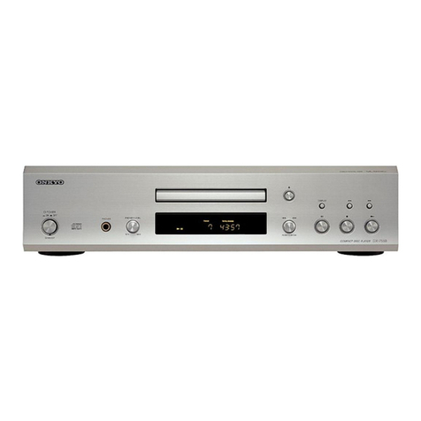
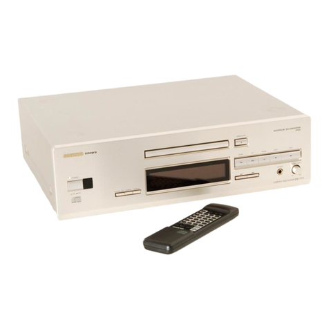
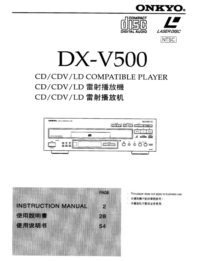
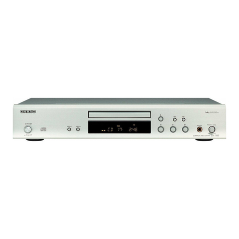
Onkyo DX-6550 User manual

DX-6550
SERIAL
NO.
3307
ONKYO.:
SERVICE
MANUAL
COMPACT
DISC
PLAYER
MODEL
DX-6550
»
Black
and
silver
models
SAFETY-RELATED
COMPONENT
WARNING!!
SPECIFICATIONS
COMPONENTS
IDENTIFIED
BY
MARK
A\
ON
THE
Signal
readout
system:
—
Optical
non-contact
SCHEMATIC
DIAGRAM
AND
IN
THE
PARTS
LIST
ARE
Reading
rotation:
About
500~200
r.p.m.
CRITICAL
FOR
RISK
OF
FIRE
AND
ELECTRIC
SHOCK.
(constant
linear
velocity)
REPLACE
THESE
COMPONENTS
WITH
ONKYO
PARTS
Linear
velocity:
1.2~1.4m/s
WHOSE
PART
NUMBERS
APPEAR
AS
SHOWN
IN
THIS
Error
correction
system:
Cross
interleave
readsolomon
MANUAL.
code
Decoded
bits:
18
bits
linear
MAKE
LEAKAGE-CURRENT
OR
RESISTANCE
MEA-
Sampling
frequency:
176.4kHz
(four-times
SUREMENTS
TO
DETERMINE
THAT
EXPOSED
PARTS
oversampling)
ARE
ACCEPTABLY
INSULATED
FROM
THE
SUPPLY
Number
of
channels:
2
(stereo)
CIRCUIT
BEFORE
RETURNING
THE
APPLIANCE
TO
Frequency
response:
5H2~20kHz
THE
CUSTOMER.
Total
harmonic
distortion:
0.003%
(at
1kHz)
Dynamic
range:
96dB
Signal
to
noise
ratio:
96dB
Channel
separation:
96dB
(at
1kHz)
Wow
and
Flutter:
Below
threshold
of
measurability
Power
consumption:
15
watts
Output
level:
2
volts
r.m.s.
Dimensions
(WXHxXD):
435131365
mm
17-1/8"
5-1/8"
x
14-7/16"
Weight:
8kg,
17.6
lbs.
ONKYO
Specifications
are
subject
to
change
without
notice.
242

DD
Giskersy0)
TABLE
OF
CONTENTS
Specifications
oiceu:
scisicses
pavsie
dew
gssaeaewse.secedsereseons
1
Service
procedures
...........ccceeceeeceea
ee
eceeeeeeeeeeneeaes
Note
on
compact
disc
.............eeceeeeeeceeeetee
een
eeeeenens
3
Protection
of
eyes
from
laser
beam
during
servicing
..
4
Laser
warning
label
...............cccceeeeeeceeeeececueeeeneens
4
Caution
on
replacement
of
pickup
.................:eeeeeees
6
Packing
View:
ss
.cssetescd.asaedanssateatanesbyenssaasadnssaartasecs
7
Chassis-exploded
View
.............ccccceceeeeeceeeeeneeneeeeees
8
Parts
St
seas
dnvaccangsyee
wis
tuas
aeyed
oie
taclacncendy
vescavesboeaeases
9
Mechanism-exploded
View
............csceeeeeceeeeeeeeenees
10
Parts:
lISt:
sve.
tsdensCreshevtnes
gitnacdats
ae
etandeeelavdenearscee.
11
Disassembling
procedures
..............ececceeeeeeeeceeeeees
11
LUbricatiOn:
o.3.05
sccpeesscceeantaver
esas
ancedaaweddecaseatneets
12
IC
block
diagram
and
descriptions
..............:..e00e0
13
Adjustment
procedures
............scceceeesceeceeceecneen
ens
22
Printed
circuit
board
view
from
bottom
side
Main:
¢ircuit'sco:.ci.2.eccsscstdvedeile
cavenettvlvavcartexteveds
25
Other
pc
boards
..........
cece
eec
eee
eec
sence
eeeeereeaenees
29
Printed
circuit
board-parts
list
.............cccceeeeeeeee
ees
27
Block
diagram
...........ccecececeeeeeeeeeeeceeeeeeeeeeeeeeneas
31
SERVICE
PROCEDURES
1.
How
to
Release
the
Transport
Lock
To
protect
the
optical
assembly
including
the
laser
pickup
from
vibration
related
damage
during
shipping,
this
unit
is
equipped
with
a
transport
lock
lever
located
on
the
base.
60+
head
screwdriver
Lock
lever
:
Hole
|
@
Usea
screwdriver
to
turn
the
lock
lever
(about
90°)
in
the
round
hole
in
the
direction
of
arrow
(
G
).
®
Before
transporting
the
unit
again,
stand
it
with
its
left
side
facing
down,
and
turn
on
the
power.
Wait
2-3
seconds
and
then
turn
the
lock
lever
in
the
opposite
direction
of
the
arrow.
Fig.
1
2.
Safety-check
out
After
correcting
the
original
service
problem,
perform
the
following
safety
check
before
releasing
the
set
to
the
customer:
Connect
the
insulating-resistance
tester
between
the
plug
of
power
supply
cable
and
chassis.
Specifications:
more
than
10Mohm
at
500V.
~2-
3.
Procedures
for
replacement
of
flat
packaged
ICs
1.
Tools
to
be
used:
(1)
Soldering
iron
....
Grounded
soldering
iron
or
soldering
iron
with
leak
re-
sistance
of
10
Mohms
or
more.
Form
of
soldering
iron’s
tip:
(2)
Magnifying
glass...
for
checking
of
finished
works
(3)
Tweezers........
for
handling
of
IC
forming
of
leads
(4)
Grounding
ring...
.
Countermeasure
for
electro-
static
breakdown
(5)
Nipper
.........
for
removing
defective
IC
(6)
Small
brush
......
for
application
of
flux
and
2.
Work
Procedures:
(1)
Remove
the
defective
IC
Cut
all
leads
of
the
defective
IC
one
by
one
using
a
nipper
and
remove
the
IC.
(2)
Clean
the
pattern
surface
of
the
PC
board.
Get
rid
of
the
remaining
leads
and
solder.
(3)
Check
and
from
the
leads
of
the
new
flat
pack-
aged
IC
to
be
installed.
From
every
lead
on
the
new
IC
using
a
pair
of
tweezers,
so
that
all
of
them
are
aligned
neatly
without
being
risen,
twisted
or
inclined
toward
one
side.
Especially
the
rising
portion
of
every
lead
must
be
formed
with
greatest
care.
IC
ee
;
IC
&
;
Ic
a
(Incliming)
(Rising)
(Twisting)
Fig.
3
(4)
Apply
flux
to
the
PC
board.
Apply
flux
to
the
pattern
surface
of
the
PC
board
which
has
been
cleaned,
as
shown
in
the
illustration.
The
area
to
be
applied
with
flux
is
the
portion
of
about
2.5mm
in
width
where
the
IC’s
leads
are
to
be
soldered.
Be
careful
to
apply
minimum
amount
of
flux
required
so
as
not
to
smear
it
on
unwanted
areas.
About
2.5
mm
Fig.
4
(5)
Temporarily
tighten
the
IC
Carefully
align
the
pattern
and
IC’s
leads,
so
that
the
IC
will
be
temporarily
tightened
to
the
pattern
on
the
four
leads
at
the
corners.
At
this
time,
sol-
dering
is
required,
but
no
need
to
apply
soldering
material.
Fig.
5
(6
—
Apply
flux
to
IC’s
leads
Apply
flux
to
the
areas
of
IC’s
leads
where
soldering
is
to
be
performed.
Be
careful
not
to
smear
flux
on
the
root
portion
of
any
lead
or
the
body
of
IC.
Apply
flux
only
to
this
portion.
(7
—
Soldering
While
attaching
the
tip
of
the
soldering
iron
to
the
soldering
point
as
shown
in
the
illustration,
feed
2
—5mm
of
soldering
wire.
Then,
slowly
move
the
iron
in
the
direction
indicated
by
the
arrow
in
the
illustration,
so
that
the
leads
will
be
soldered
to
the
pattern.
Move
the
iron
in
the
rate
of
approxi-
mately
lcm
in
Ssec.
Proceed
with
your
work
while
confirming
a
clean
fillet
of
solder
is
formed
on
each
lead,
subsequent
to
the
melting
of
flux.
Soldering
wire
Fig.
7
Soldering
iron
CAUTION
1)
If
you
move
the
iron
too
quickly,
loose
soldering
is
likely
to
result.
2)
Be
especially
careful
‘when
soldering
the
first
lead
where
loose
soldering
is
most
liable
to
be
formed.
(8)
Check
the
results
When
soldering
of
all
leads
is
finished,
check
the
soldered
portion
on
every
lead
with
a
magnifying
glass.
A
tester
must
not
be
used
or
checking
of
any
soldered
position
NOTE
ON
COMPACT
DISC
@
Holding
Compact
Discs
Hold
Compact
Discs
by
the
edges
so
that
you
do
not
touch
ae
DX-6550
the
surface
of
disc.
Remember
that
the
side
of
the
disc
with
the
“rainbow”
reflection
is
the
side
containing
the
audio
information.
Do
not
attach
tape
or
paper
to
the
label
side
of
the
disc
and
always
be
careful
not
to
leave
fingerprints
on
the
side
that
is
played.
@
Storing
Compact
Discs
Store
Compact
Discs
in
a
location
protected
from
direct
sunlight,
high
heat
and
humidity
and
extremely
high
and
low
temperatures.
Discs
should
never
be
left
in
the
trunk
or
interior
of
an
automobile
in
the
sun
since
the
temperature
can
become
very
high
in
such
a
closed
environ-
ment.
Always
store
Compact
Discs
in
the
holders
in
which
they
were
sold.
Never
leave
a
disc
in
the
player’s
disc
holder
for
a
long
period
of
time.
Not
this
way
Fig.
8
©
Cleaning
Compact
Discs
Before
playing
a
disc
wipe
off
the
playing
surface
with
a
soft
cloth
to
remove
dust
and
other
soil.
Wipe
the
surface
in
straight
lines
from
the
center
of
the
disc
outward,
not
in
a
circular
motion
as
you
would
with
a
phonograph
record.
Do
not
use
benzene,
chemical
cleansers
or
phonograph
record
cleaning
solutions
to
clean
Compact
Discs.
Also
avoid
static
electricity
prevention
solutions
since
they
can
damage
the
surface
of
Compact
Discs.
Problems
Caused
by
Dew
Dew
can
form
inside
a
Compact
player
when
it
is
brought
from
a
cold
environment
into
a
warm
room,
when
a
room
is
rapidly
heated
and
if
a
player
is
left
in
a
humid
environ-
ment.
This
dew
can
prevent
the
laser
pickup
from
reading
the
data
contained
in
the
pits
in
the
disc
surface.
If
the
player
does
not
operate
properly
because
of
dew,
remove
the
disc
and
leave
the
player’s
power
switch
on
for
about
one
hour
to
remove
all
moisture.

DX-6550
PROTECTION
OF
EYES
FROM
LASER
BEAM
DURING
SERVICING
This
set
employs
a
laser.
Therefore,
be
sure
to
follow
carefully
the
instructions
below
when
servicing.
WARNING!!
WHEN
SERVICING,
DO
NOT
APPROACH
THE
LASER
EXIT
WITH
THE
EYE
TOO
CLOSELY.
IN
CASE
IT
IS
NECESSARY
TO
CONFIRM
LASER
BEAM
EMMISION,
BE
SURE
TO
OBSERVE
FROM
A
DISTANCE
OF
MORE
THAN
30cm
FROM
THE
SURFACE
OF
THE
OBJECTIVE
LENS
ON
THE
OPTICAL
PICK-UP
BLOCK.
LASER
WARNING
LABEL
The
label
shown
below
are
affixed.
1.
Warning
label
Laser
Diode
Properties
@
Material:
GaAS/GaAlAs
®
Wavelength:
780nm
@
Emission
Duration:
continuous
@
Laser
output:
max.
0.5mW*
*This
output
is
the
value
measured
at
a
distance
about
1.8mm
from
the
objective
lens
surface
on
the
Optical
Pick-up
Block.
DANGER
RNVISIBLE
LASER
RADIATION
WHEN
OPEN
AND
INTERLOGK
FAILED
OR
DEFEATED.
AVOID
DIRECT
EXPOSE
fe
BEAM
CAUTION
—sazarpous
Laser
ano
ELECTROMAGNETIC
RADIATION
WHEN
OPEN
ANO
INTERLOCK
DEFEATED.
ATTENTION
—aavonnement
LASER
ET
ELECTROMAGNETIQUE
DANGER
QUVERT
AVEC
L
ECLENCHEMENT
DE
SeCURITE
ULE.
SN
2936091)
ADVARSEL:
USYNLIG
LASERSTRALING
VED
ABNING,
NAR
SIKKERHEDSAF-
BRYDER
ER
UDE
AF
FUNKTION.
UNDGA
UDS/ETTELSE
FOR
STRALING.
Photo
1

2.
Class
1
label
This
label
is
located
on
the
back
panel.
Photo
2
ADVARSEL
Denne
merkning
er
anbragt
pa
apparatets
h@jre
side
og
indikerer,
at
apparatet
arbejder
med
laserstraler
af
klasse
1,
hvilket
betyder,
Sconce
at
der
anvendes
laserstraler
af
svageste
klasse,
og
at
man
ikke
pa
apparatets
yderside
kan
blive
udsat
for
utilladelig
kraftig
striling.
APPARATET
B@R
KUN
ABNES
AF
FAGFOLK
MED
SAERLIGT
KENDOSKAB
TIL
APPARATER
MED
LASERSTRALER!
Indvendigt
i
apparatet
er
anbragt
den
her
gengivne
advarselsmerk-
ning,
som
advarer
imod
at
foretage
saédanne
indgreb
i
apparate,,
at
man
kan
komme
til
at
udsztte
sig
for
laserstraling.
AOVARSEL:
USYNLIG
LASERSTAALING
VEO
ABNING.
NAR
SIKKERHEDSAF
BRYDER
ER
UOE
AF
FUNKTION
UNOGA
UDSATTELSE
FOR
STRALING
VAROITUS!
Laite
sisaltéa
laserdiodin,
joka
lahettaa
(nakyma-
tonta)
silmille
vaarallista
lasersateilya.

CAUTION
ON
REPLACEMENT
OF
PICKUP
The
laser
diode
in
the
optical
pick-up
block
is
so
sensitive
During
repair,
carefulley
take
the
following
precautions.
to
static
electricity,
surge
current
and
etc.
that
the
com-
(The
following
precautions
are
included
in
the
service
ponents
are
liable
to
be
broken
down
or
its
reliability
parts).
remarkably
deteriorated.
PRECAUTIONS
1,
Ground
for
the
work-desk.
3.
Grounding
for
the
human
body.
Place
a
conductive
sheet
such
as
a
sheet
of
copper
(with
impedance
lower
than
10°)
on,
the
work-
desk
and
place
the
set
on
the
conductive
sheet
so
that
the
chassis.
.
Grounding
for
the
test
equipment
and
tools.
Test
equipments
and
toolings
should
be
grounded
in
order
that
their
ground
level
is
the
same
the
ground
of
the
power
source.
Be
sure
to
put
on
a
wrist-strap
for
grounding
whose
other
end
is
grounded.
Be
particularly
careful
when
the
workers
wear
synthetic
fiber
clothes,
or
air
is
dry.
.
Select
a
soldering
iron
that
permits
no
leakage
and
have
the
tip
of
the
iron
well-grounded.
.
Do
not
check
the
laser
diode
terminals
with
the
probe
of
a
circuit
tester
or
oscilloscope.
Wrist-st
rap
Disconnection
To
solder
@
position
and
®)
position
on
the
terminal
PC
board
before
removing
the
optical
pickup.
Connection
The
optical
pick-up
of
service
part
has
a
protective
so
Ider
bridge
for
@
position.
That
must
be
removed
after
connecting
the
pickup.
Then,
remove
a
protective
to
Ider
bridge
for
®)
position.
Fig.
11

1D)
Giloketes)
PACKING
VIEW
Remote
Connection
Controller
Cord
/
Batteries
fi]
Lift
up
the
back
side
of
unit
and
return
the
pickup
to
innnermost.
Use
a
screwdriver
to
turn
the
lock
lever
(about
90°)
in
the
round
hole
in
the
direction
of
arrow.
(Clockwise)
REF.
NO.
PART
NO.
DESCRIPTION
1
29361123
Label
2
282301
Sealing
hook
3
29051749
Master
carton
box
(Black)
29051750
Master
carton
box
(Silver)
4
29095012-1
500
800mm,
Protection
sheet
5
29100105
550x680mm,
Poly-vinyl]
bag
6
29361047
Label,
sheet
7
29095572
Sheet
8
29091264
Pad
L
9
29091265
Pad
R
10
261504
Adhesive
tape
11
29110071
Damplon
tape
12
260012
Damplon
tape
13
Accesarry
bag
ass’y
29341302
Instruction
manual
2010097
Connection
cord
24140028
RC-122C,
Remote
controller
3010054
UM-3,
Two
batteries
2010169
Cord
RI
29365020
Warranty
card
29100094A
Poly
bag
for
warranty
card
29100097
Poly-vinyl
bag
29091309
Pad,
tray
panel


PARTS
LIST
REF.
NO.
Al
A2
A3
A4
A5
A6
A7
A8
A9
A10
All
Al2
Al3
Al4
Al5
Al6
Al7
Alg
Al9
A20
A21
A22
A23
A24
A25
A26
A27
A28
A29
A30
A31
A4l
Adil
A42
A43
A44
ASI
ASI
A52
AS53
ASS
AS7
AST
A58
ASO
PART
NO.
27100170A
27100169A
27130542
27130543B
27141311
27121165
27175011C
28140873
27300750
27273101A
27270278
27300833
28140903
27270214A
27270212
28133202
870060
27267558-1
27141281
830440109
834430108
834430088
831130088
834230108
834430068
838440089
27301184
27141310
27141309
28140918
27110433
27110434
28184401
28184402
838440089
834430088
28140408
1H050121
1H049121
28191477
27211045
27210988
27175153
84643008
84633008
834430088
833430080
DESCRIPTION
Chassis
Chassis
U
Bracket
C
Bracket
L
Bracket
T
Back
panel
Leg
(Cushion)
Cushion
AStrainrelief
Joint,
power
Spacer
WS-2NS,
Clamper
Cushion
Spacer
Spacer
Back
plate
W315,
Flat
washer
Guide
Bracket
4TTC+10C
(BH),
Tapping
screw
3TTS+10B
(BC),
Tapping
screw
3TTS+8B
(BC),
Tapping
screw
3TTW+8B,
Tapping
screw
3TTS+10B
(Ni),
Nickel
screw
3TTS+6B
(BC),
Tapping
screw
4TTB+8C
(BC),
Tapping
screw
Lock
pin
Bracket,
rail
Bracket
Cushion
Front
bracket
ass’y
(B)
Front
bracket
ass’y
(S)
Top
cover
(B)
Top
cover
(S)
4TTB+8C
(BC),
Tapping
screw
3TTS+8B
(BC),
Tapping
screw
t3x
10x36,
Cushion
Front
panel
ass’y
(B)
Front
panel
ass’y
(S)
Clear
plate
Panel,
door
(Tray
panel)
(B)
Panel,
door
(Tray
panel)
(S)
Leg
SESH
RSEN
(BC),
Special
bolt
3HSBXx8FN
(Cr),
Special
bolt
{S)
3TTS+8B
(BC),
Tapping
screw
3TTP+8P
(BC),
Tapping
screw
REF.
NO.
PART
NO.
DESCRIPTION
A60
27270255
Spacer
A81
28323433
Knob
(B)
28323434
Knob
(S)
A82
28323152
Knob
MODE
(B)
28323435
Knob
MODE
(S)
A83
27301187
Cushion
L
P801
253148
or
A
AS-CEE
250V
2.5A,
253150
Power
supply
cord
T901
2300342
A\NPT-1004G,
Power
transformer
Ul
1H048563-1A
NAAR-3363-1A,
Main
circuit
pc
board
ass’y
U2
1H048564-1
NADG-3364-1,
Opto./digital
output
pe
board
ass’y
U3
1H048565-1
NADIS-3365-1,
Display
circuit
pe
board
ass’y
U4
1H048566-1
NAPS-3366-1,
Power
switch
pc
board
ass’y
US
1H048567-1
NAAF-3367-1,
Headphone
amplifier
pc
board
ass’y
U6
1H048568-1
NAAF-3368-1,
Headphone
terminal
pe
board
ass’y
U7
1H048569-1
NASW-3369-1,
Switch
pe
board
ass’y
Wi
260208
Binder
NOTE:
(B):
Only
Black
model
(S):
Only
Silver
model
NOTE:
THE
COMPONENTS
IDENTIFIED
BY
MARK
A
ARE
CRITICAL
FOR
RISK
OF
FIRE
AND
ELECTRIC
SHOCK.
REPLACE
ONLY
WITH
PART
NUMBER
SPECIFIED.
Oo
a
fer)
oy
3]
i)

MECHANISM-EXPLODED
VIEW

PARTS
LIST
REF.
NO.
PART
NO.
DESCRIPTION
1
1H048901
Spindle
motor
ass’y
3
27270264-1
Spacer
4
82542010
2B+10F(BC),
Binding
screw
5
24110003
DLBA2Z2001A,
Optical
pickup
6
27260286
Shaft
7
27270264-1
Spacer
8
27301129B
Plate
9
28181020
Magnet
ass’y
10
27301152
York
ass’y
11
245022364
Coil
12
28140912
Cushion
A
13
28140913
Cushion
B
14
28140914
Cushion
C
15
82542006
2B+6F(BC),
Binding
screw
16
833420068
2TTP+6B(BC),
Tapping
screw
17
831430100
3TTW+10P(BC),
Tapping
screw
18
801414
Special
screw
19
27301179
Weight
PU
21
27100166C
Chassis
L
22
28140891
Cushion
A
23
27301131B
Arm
24
29360911
Label
LASER
3
25
27180402
Spring
26
27301132A
Cap
CH
27
28181019A
Magnet
CH
28
27301133
York
CH
30
27301134
Cushion
rubber
31
27180403A
Spring
F
32
27180404B
Spring
R
33
28140860
Cushion
34
27270277
Spacer
35
27301172
Cushion
rubber
36
28180417
Spring
G
37
27301182
Cushion
L
39
28140917
Tube
41
27301124
Disc
tray
DISASSEMBLING
PROCEDURES
Top
cover
Remove
a
screw
holding
the
back
panel
and
top
cover.
Remove
the
four
screws
holding
the
top
cover
and
chassis.
Main
circuit
PC
board
Remove
the
top
cover.
Remove
the
eight
screws
holding
the
back
panel
and
chassis.
Remove
a
screw
holding
the
bracket
C
and
opto./digital
output
PC
board.
Remove
four
screws
holding
the
main
PC
board
and
chassis.
Tray
panel
Use
a
hexagon
wrench
(2.5mm),
remove
the
two
hexagon
bolt
holding
the
tray
panel
and
mechanical
chassis.
Mechanism
ass’y
Remove
the
tray
panel.
Remove
the
four
screws
holding
the
mechanism
and
chassis.
-11-
DX-6550
REF.
NO.
PART
NO.
DESCRIPTION
42
27301135
Rail
L
43
27301136
Rail
R
44
27301126
Guide
bearing
45
28140892
Cushion
T
Si
27301137B
Disc
plate
52
27301138
Cam
plate
L
53
27301139A
Cam
plate
R
54
27260280A
Shaft
55
27301140A
Stopper
56
27301141A
Plate
57
27141275
Bracket
61
27260281A
Shaft
62
27141274
Bracket
63
27270265A
Spacer
64
27270276
Spacer
65
27180418
Spring
71
1H048902
Disc
motor
ass’y
73
27301142
Pulley
gear
74
27301143A
Flat
wheel
75
27301162
Rubber
belt
76
25065322
NMS-1214,
Microswitch
77
2000888
Socket
ass’y
78
1H048559-1
NAETC-3359-1,
Terminal
pc
board
ass’y
79
27301180
Cushion
81
82143004
3P+4FN(BC),
Pan
head
screw
82
831126060
2.6TTW+6P,
Tapping
screw
83
838430088
3TTB+8B(BC),
Tapping
screw
84
834430068
3TTS+6B(BC),
Tapping
screw
85
834430088
3TTS+8B(BC),
Tapping
screw
91
28140908
Cushion
K
92
28140909
Cushion
L
93
28140910
Cushion
F
94
.
27141317
Bracket,
switch
95
834440168
4TTS+16B(BC),
Tapping
screw
96
28140911
Cushion
P
Caution:
When
disconnect
the
sockets
P101
anj
7102
on
the
main
circuit
PC
board,
solder
th:
3
point
on
the
terminal
PC
board
or
the
A
pont
on
the
pickup.
(Refer
page
6)
After
remove
the
flexible
PC
board
of
pickup
from
terminal
FC
board,
remove
the
terminal
PC
board.

DX-6550
LUBRICATION
Cam
Piste
R
Chassis
L
6902S
Cam
Plate
L
6902S
Dise
Tray
ZB
—-~
62025
On
Spacer
—12-

Dx-6550
|
-DX-6550
IC
BLOCK
DIAGRAM
AND
DESCRIPTIONS
74HCOOP
(NAND
gate)
‘74HCU04P
(Hex
inverters)
CXA1081S
(RF
Amp)
Vcc
ASYMMETRY
COMPARATOR
AUTO
(Top
View)
FOK
AMP
EFM
OMPARATOR
ays
74HC86P
(Exclusive
OR)
TRACKING
ERROR
AMP
wi
et
3
>a
Veco
4B
GA
AY
3B
3A
3Y
O
DEFECT
BOTTOM
HOLO
CURRENT
REFERENCE
RF
1-¥
AMP
(1)
©)
©)
©)
(2)
2)
©)
6
é
g
Ed
8
8
4
=
”
8
w
x
Qo
RFO
RF
O
Input
terminal
of
output
signal
of
RF
summing
16
cc
amplifier
via
the
coupling
capacitor
M51943ASL
(System
reset)
STA341M-L
(Transistor
array)
Defect
bottom
hold
output
terminal
Output
terminal
of
RF
summing
amplifier
17
Vee
Negative
power
supply
terminal
3
RF
Input
terminal
of
RF
summing
amplifier
18
FE
BIAS
Non-inversion
bias
terminal
of
focus
error
amplifier
1
ra
feedback
CMR
adjustment
of
focus
error
amplifier
Switching
terminal
of
P-SSUB/N-SURB
of
LD
4
P/N
(laser
diode)
I
19
FE
Output
terminal
of
focus
error
amplifier
5
LD
Output
terminal
of
APC
LD
amplifier
20
TE
Output
terminal
of
tracking
error
amplifier
2
8
3
74
6
=
Input
terminal
of
APC
PD
(Pin
diode)
amplifier
21
DEFECT|
Output
terminal
of
defect
comparator
Inversion
input
terminal
of
RF
I-V
amplifier
(1)
22
MIRR
|
Output
terminal
of
mirror
comparator
Connect
to
At+C
of
PIN
diodes.
Er):
8
PD2
Inversion
input,
terminal
of
RF
I-V
amplifier
(2)
23
cP
ener
terminal
of
capacitor
for
mirror
Connect
to
B+D
of
PIN
diodes.
cz
hold
Non-inversion
input
of
mirror
comparator
|
i
Connection
i
i
terminal
of
capacitor
for
defect
9
ve
Connect
to
GND.
24
CB
bottom
hold
NJM4556S
(Operation
ain
)
Inversion
input
terminal
of
F
I-V
amplifi
a]
eee
‘i
nversion
input
terminal
o
-V
amplifier
10
F
Connect
to
F
of
PIN
diode.
L
25
DGND
|
Connect
to
GND
Far:
.
igs
i.
11
E
Lee
eit
dies
EVrampries
26
ASY
Auto
asymmetry
control
input
terminal
eee
|
Output
terminal
of
E
I-V
amplifier
27
EFM
|
Output
terminal
of
EFM
comparator
Feedback
input
terminal
of
E
I-V
amplifier
|
:
13
El
Gain
adjustment
of
E
I-V
amplifier
28
FOK
|
Output
terminal
of
FOK
comparator
DC
voltage
output
terminal
of
(Vcc
+
Vee
y2
29
LD
or
|
ON/OFF
switching
terminal
of
laser
diode
a
i
30
Vec
Positive
power
supply
Input
terminal
from
defect
bottom
hold
output
signal
via
the
coupling
capacitor
VIDE-V07006
/
Druck
1

DX-6550
16BT-09GK
(Fluorescent
tube)
Pin
connection
PIN
NO.
r
CONNECTION
CONNECTION
G
B1630
(Motor
Drive)
Voutl
Vout2
Pin6=NC
NJM592D8
(Wide
band
amp.)
INPUT
2
1
—E
INPUT
1
GIB GIA
cain
secect
U2]
GAIN
SELECT
vs
[3]
|
6]
vs*
OuTPUT2
[s]
OuteuT?
VIDE-V07006
/
Druck
2
T,1
16
Vop
18
T,
14T,
13co
IZAiN
11
Bin
100
9a
0222
520
el
afo}n|
ml
off
elelel
a
ECE
CET
12;11)10}9)8/7/6/5)4}3])2;1)/N/N|IN|NININ|NIN|NIN/F
G|G|G|G/G/G|G|G|G|G|G|G|
P| P| P|
P|
P| P|
P} P|
P}
P|
2
HD14538BP
(Muitivibrator)
1
F
2
Symbol
2
3
4
5
6
8
DECT
XRST
|
Reset
input
terminal.
Reset
at
the
ley
fe-vel.
14
TGU
Time
constant
terminal
for
high
frequency
gain
switching
of
tracking.
js
CXA1082A0
(Servo
Signal
Processor)
INPUT
SHIFT
REGISTERK
_'
|
ADDRESS
DECODER
TL
DATA
REGISTER
SEQUENCER
OUTPUT
DECODER
FSim4
TGir2
TMIi-7
PS!I-3
Function
Pin
No.
Defect
signal
input
terminal.
15
a,
Tracking
error
signal
input
terminal.
Tracking
zero
cross
comparator
input
terminal.
Window
comparator
input
terminal
for
ATSC
detection.
Focus
error
singal
input
terminal.
20
Insert
the
capacitor
between
this
terminal
and
21
pin
9
when
drop
the
high
frequency
gain
of
focus
servo.
om)
Switching
terminal
of
high
frequency
gain
of
focus
servo.
3
FSET
Time
constant
switching
terminal
when
raise
the
low
frequency
gain
of
focus
servo.
Focus
drive
output
terminal.
Inversion
input
terminal
of
focus
amplifier.
Time
constant
terminal
to
make
the
fous
search
waveform.
Symbol
Function
TG2
Time
constant
terminal
for
high
frequency
gain
switching
of
tracking.
17
TAO
|
Tracking
drive
output
terminal.
Inversion
input
terminal
of
tracking
anplifier.
Non-inversion
input
terminal
of
sled
amplifier.
24
26
2
SLO
Sled
drive
output
terminal.
SL-
Inversion
input
terminal
of
sled
amplfier.
SSTOP
Limit
switch
ON/OFF
detector
signal
terminal
for
disc
innermost
position
detector.
Terminal
for
peak
of
phase
compensitionm
of
tracking
and
fo
setting
LPF.
FZC,
AS,
TZC,
SSTOP
and
etc.
sigials
are
output
by
the
command
from
microprocessor.
SENS
Cc.
OUT
Signal
output
terminal
for
count
of
tack
numbers.
DIRC
|
Use
when
jumps
one
track.

Pin
No.
}
Symbol
Function
Pin
No.
|
Symbol
Function
Pin
No.
|
Symbol
Function
Pin
No.
|
Symbol
Function
29
DATA
|
Serial
data
input
terminal
from
microprocessor.
Connection
terminal
to
terminal
MDP
of
Time
constant
switching
output
terminal
of
49
RAWE,
|
Write
enable
signal
output
to
external
RAM
40
MDP
1
FSW
!
:
; ;
CXD1125QZ.
output
filter
of
spindle
motor
30
XLT
|
Latch
input
terminal
from
microprocessor.
; ;
50
RACS
|
Chip
selector
signal
output
to
external
RAM
:
:
: :
41
MON
|
Connection
terminal
to
terminal
MON
of
2
MON
|
ON/OFF
control
output
terminal
of
spindle
—
31
CLK
|
Clock
input
terminal
serial
data
transmitter
CXD1125QZ.
5
motor
51
C4M_
|
Divider
output
of
crystal.
f=4.2336MHz
from
microprocessor.
pe
ce
et
[eee
: :
42
FSW
LPF
time
constant
terminal
of
CLV
servo
error
Drive
output
terminal
of
spindle
motor.
52
Vss
Ground
33
BW
Time
constant
terminal
of
loop
filter.
signal.
3
MDP
Rough
control
when
mode
CLV-S
and
phase
—
:
We
os
g
5
control
when
mode
CLV-P
53
XTAI
|
Input
terminal
of
crystal
oscillator
34
PDI
Input
terminal
of
phase
comparator
output
PDO.
44
SPDL—
Inversion
input
terminal
of
spindle
drive
fail
eA
Ics
s
amplifier.
4
MDS
Drive
output
terminal
of
spindle
motor.
54
XTAO
j
Output
terminal
of
crystal
oscillator
35
ISET
Flow
the
current
to
decide
the
focus
search,
Speed
control
when
mode
CLV-P
i
track
jump,
and
kick
height.
45
SPDLO
|
Spindle
drive
output
terminal.
55
MDi
:
: : ,
5
EFM EFM
signal
input
terminal
from
RF
amplifier
2
Mode
switching
input
terminals
36
VCOF
VCO
free
run
frequency
is
proportion
to
46
WDCK
|
Clock
input
terminal.
(88.2kHz)
57
MD3
resistor
value
between
pins
31
and
37.
;
”
6
ASY
Output
terminal
to
control
the
slice
level
of
ee
ah
+—
4
;
47
FOK
Focus
OK
input
terminal.
EFM
signal
58
SLOB
Code
switching
input
of
audio
data
output.
38
C864
|
VCO
(8.64MHz)
output
terminal.
eee
Seton
See
;
; -
Seine
En
eaas
,
Ta
48
MIRR
|
Mirror
signal
input
terminal.
7
LOCK
|
GFS
sampling
terminal
Mode
switching
input
of
audio
data
output.
zi
89...
||
BOCK:
||
Ried
miClOe
Fun
away
Prevenbon:
cxeMIe
Is
a
7
ee
—|
59
|
PSSL_
|
Serial
output
at
low
level
operated
at
low
level.
VCO
output
terminal.
8.6436MHz
when
lock
Parallel
output
at
high
level
——
8
VCOO
|
to
EFM
signal
woe
.
&
x
8
=“
Control
output
for
aperture
correction.
CXD1
125QZ
(Digital
signal
processor)
3
&
2
9
vcol
VCO
input
terminal
60
APTR
High
level
when
Rch.
(24)
10
TEST
OV
;
Control
output
for
aperture
correction.
|
61
APTL
High
level
when
Lch.
Phase
comparator
output
terminal
of
EFM
il
PDO
signal
and
VCO/2
62
DAO1
DAO1
(LSB
of
parallel
sound
output)
output
{ro
=
when
PSSL
=
H.
C1F1
output
when
PSSL
=
L
SUBCODE
SUBCODE
SUBCODE
Q
12
Vss
Ground
—_—__
—}
SYNC
DETECTOR
DEMODULATOR
REGISTER
: :
-
-
63
DA02
DAOQ2
output
when
PSSL
=
H.
13
CLK
Serial
data
transmitter
clock
input
terminal
from
C1F2
output
when
PSSL
=
L.
microcomputer
—
64
DAQ3
DAO3
output
when
PSSL
=
H.
14
XLT
Latch
input
terminal
from
microcomputer
C2F1
output
when
PSSL
=
L.
Serial
data
input
terminal
from
microcomputer
65
DAO4
DA04
output
when
PSSL
=
H.
A
C2F2
output
when
PSSL
=
L.
23
BIT
System
rest
input
terminal.
C2FL
output
when
PSSL
=
L.
poe
17
CNIN
|
Tracking
pulse
input
terminal
7
;
67
DA06
DA06
output
when
PSSL
=
H.
|
{
18
SENS
Inner
condition
output
terminal
correspond
to
C2PO
output
when
PSSL
=
L.
address
68
DAO7
DAO7
output
when
PSSL
=
H.
19
MUTG
|
Muting
input
terminal
RFCK
output
when
PSSL
=
L.
ERROR
DETECTOR
20
CRCF
|
CRC
check
output
terminal
of
subcode
Q
69
pAog
|
PA08
output
when
PSSL
=
H.
INSERTER
CORRECTOR
|
:
:
:
WFCK
output
when
PSSL
=
L.
21
EXCK
Clock
input
terminal
for
serial
output
of
subcode
70
DAO09
DAO9
output
when
PSSL
=
H.
=|
PLCK
output
when
PSSL
=
L.
22
SBSO
|
Serial
output
terminal
of
subcode
t
;
4
71
DA10
DA1O
output
when
PSSL
=
H.
23
SUBQ
|
Subcode
Q
output
terminal
UGFS
output
when
PSSL
=
L.
VCO
CIRCUIT
——+
—
TIMING
INTERPOLATOR
Subcode
sink
SO
+
S1
output
terminal
DA11
output
when
PSSL
=
H.
GENERATOR
72
|
DAIL
|
Grop
output
when
PSSL
=
L.
25
SQCK
|
Clock
terminal
to
read
the
subcode
Q
t-———
73
Vop
Power
supply
(5
V)
26
SQEX
27
DOTX
Selector
input
terminal
of
SQCK
DA12
DA12
output
when
PSSL
=
H.
RAOV
output
when
PSSL
=
L.
Digital
output
terminal
Indicator
output
of
lock
condition
of
frame
DA13
output
when
PSSL
=
H.
X?
TAL
CIRCUIT
TIMING
OIGITAL
FILTER
GENERATOR
Cx01130Q
syne
DA13
|
C4LR
output
when
PSSL
=
L.
(Exp
135Q
DA14
DA14
output
when
PSSL
=
H.
Data
terminals
of
external
RAM
C210
output
when
PSSL
=
L.
DAIS
DA15
output
when
PSSE
=
H.
=I
C210
output
when
PSSL
=
L.
DAI6
DA16
(MSB
of
parallel
sound
outjut)
output
when
PSSL
=
H.
DATA
output
wien
PSSL
=
L
Strobe
signal
output.
176.4kHz
wien
DF
is
on.
WDCK
|
38
2kHz
when
DF
is
off.
TRACKING
RAM
ADDRESS
COUNTER
GENERATOR
OIGITAL
OUT
(ee
38a)
Data
terminals
of
external
RAM
CxXD1135Q
Address
output
terminals
of
external
RAM
2
48
RAI1
LRCK
|
Strobe
signal
output.
88.2kHz
whn
D
F
is
on.
44.1kHz
when
DF
is
off.
VIDE-V07006
/
Druck
3

DX-6550
©
DX-6550
CXP5058H-104QZ
(Microprocessor)
__
Pin
No.
.
Symbol
VO
|--.
Descriptions
G02
ios
aids
1~12
.
a
.
ne
2
Fluorescent
indicator
tube
segment
output
terminals.
Active
high.
RE
AMP.
SERVO
SIGNAL
DIGITAL
SIGNAL
ees
fran
|
RROCESSOR
ERcroe
13~28
16G~1G
O
|
Fluorescent
indicator
tube
grid
output
terminals.
Active
high.
{
tf
{
29
SCOR
I
Sub
code
sink
input
terminal.
Leading
pulse
(75Hz)
is
input
during
play.
31
C4M
I
Reference
clock
input
terminal.
f=4.23MHz
32
RST
VO
||
Reset
input
terminal.
Reset
at
low
level
when
the
power
switch
turns
on.
Peden’
i
34
VDD
|_|
+5V
power
supply.
ReMogon
te
a
35~42
ADO~AD7
I
A/D
converter
input
terminals
for
key
input.
Ao?
:
44
SC
O
Servo
system
serial
command
clock
(CLK)
and
sub
code
Q
read
clock
(SQCK)
output
terminal.
a
45
DATA
ia
O
Data
output
terminal
of
serial
command
of
servo
system.
2
46
SUBQ
oa
Input
terminal
of
sub
code
Q.
47
SQCK
ear
Oo
Read
clock
output
control
terminal
of
sub
code
Q.
:
48
CLK
|
oO
|
Clock
output
control
terminal
of
serial
command
of
servo
system.
_|
49
XLT
O
Latch
command
output
terminal
of
serial
command
of
servo
system.
aie
—
|
50
=
PLAY
{
oO
Play
indicator
output
terminal.
Not
passe
@
51
OPEN
oO
Tray
open
operation
output
terminal.
Open
at
low
level.
+5V
62)
52
He
CLOSE
L
O
Tray
close
operation
output
terminal.
Close
at
low
level.
ae
i
53
—
MUT
oO
Audio
muting
control
output
terminal.
Muting
turns
off
at
low
level.
x
54
EMP
O
Emphasis
switch
control
output
terminal.
Active
high.
55
SENSE
I
This
terminal
is
input
the
conditions
of
servo
system
according
serial
command
of
servo
i
|
_[
system.
ei
56
FOK
I
Focus
OK
input
terminal.
This
terminal
is
the
high
level
when
focus
servo
operates.
57
IN
SW
I
Close
switch
input
terminal.
L
when
the
close
switch
turns
on.
58
OUT
SW
I
Open
switch
inut
terminal.
L
when
the
open
switch
turns
on.
tee
ae
oe
ty
59
LSR
O
Laser
diode
ON/OFF
control
output
terminal.
ON
at
low
level.
Segment
Grid
60
NRSC
OUT
oO
System
code
output
terminal.
62
NRSC
IN
I
System
code
input
terminal.
63
TIMER
PLAY
I
Timer
play
swich
input
terminal.
Time
play
at
low
level.
64
TIMER
SHUFFLE
I
Timer
shuffle
switch
input
terminal.
Timer
shuffle
at
low
level.
65~70
MODE
4, 5,
0,
1,
2,
3
I
Mode
input
terminals.
71
Vss
Connect
to
GND.
2
76
VEDP
Power
supply
terminal
for
fluorescent
indicator
tube.
(—30V)
i
77~80
o,a,
bf
To
Fluorescent
indicator
tube
segment
output
terminals.
Active
high.
|
MODE
0
MODE
2
MODE
3
|
MODE
4
SREC
SELECTOR
|
PICKUP
SELECTOR
|
NRSC
SELECTOR
KICK
SELECTOR
|
TRAY
SELECTOR
HIGH
(+5V)
|
1
sec
wait
ALPS
ONLY
(DCHG,
OSTP)
Max
128
tracks
Speed
down
Speed
const
MEMORY
ARRAY
128x
128
VIDE-V07006
/
Druck
4

BD
Gistores
0)
8D-3170-1
(DAC
unit)
Analog
positive
power
supply
Vcc
®
26
RVO_
Rch
hold
output
Opto.
drive
reference
voltage
output
VRP
2
‘
RDO
Rch
deglitching
output
Optc.
drive
voltage
divided
output
+VRD
$
7
RDI
Reh
deglitching
input
DA
converter
power
supply
DRO
@
i
RIO
——-Rch
integrator
output
Opto.
¢
‘ive
opamp.
negative
input
DRI
6
22
Ril
—
Rech
integrator
input
N.C.
a
AGND
Analog
ground
Digital
ground
DGND
b ®
VRO
DA
converter
reference
voltage
Digital
positive
power
supply
VL
Lil
Lch
integrator
input
N.C.
b
L10
—_Lch
integrator
output
System
clock
input
MCLK
Z
®
LDI
Leh
deglitching
input
16.9344MHz
|
|
DATA
input
DATA
@
re
LDO
Lech
deglitching
output
Bit
Oe
au
BLCK
@
6
LVO—_Lch
hold
output
®
@
-Vcc
Analog
negative
voltage
Channel
clock
input
+LRCK
44.1kHz
.
21-

DX-6550
ADJUSTMENT
PROCEDURES
Instruments
required
Dual
trace
oscilloscope,
Frequency
counter,
AF
oscillator,
Test
disc
(SONY
YEDS-18),
AC
voltmeter,
Jitter
meter,
and
Socket
P4(Part
no.
25050138)
1.
VCO
frequency
adjustment
Connect
the
frequency
counter
to
terminal
P110.
Turn
the
power
switch
to
ON.(No
load
the
disc.)
Adjust
R147
until
the
frequency
counter
reading
becomes
4322
+5kHz.
After
adjustment,
disconnect
the
frequency
counter.
1
2.
Focus
offset
adjustment
9
|
Load
the
test
disc
YEDS-18
on
the
tray
and
play
the
track
2.
GND
Connect
the
oscilloscope
or
jitter
meter
to
terminal
P109.
(Oscilloscope)
Adjust
R110
until
a
clear
trace
of
waveform
pattern
as
shown
photo
1
appear
on
the
oscilloscope.
When
the
amount
of
jitter
is
broad,
set
R110
to
mechanical
center.
(Jitter
meter)
Adjust
R110
until
the
jitter
meter
reading
becomes
minimum.(Less
than
10ns.)
After
adjustment,
disconnect
the
oscilloscope
or
jittter
meter.
Frequency
P110
counter
PLCK
+
Oscilloscope
range
Vertical
:
0.5
V/div.
Holizontal
:0.2
ps/div.
DC,
Ground:
Center
Photo
1
3.
Tracking
offset
adjustment
Connect
the
short
clip
between
TP105
and
Ground
of
digital
section.
Turn
R125
to
minimum
position.(Counter
clockwise)
Connect
the
oscilloscope
between
pin
3
(TR)
of
P108
and
pin
2
(GND)
of
P109.
Adjust
R108
until
the
center
of
tracking
error
signal
on
the
oscilloscope
becomes
GND
level.
Turn
R125
to
the
mechanical
center.
After
adjustment,
disconnect
the
oscilloscope
and
short
clip.
P108
TR
Oscilloscope
A
----}--GND
level
P109
Vertical:
1V/div
-
B
Holizontal
:
1
ms/div.
5
GND
DC,
Ground:
Center
A=B
Photo
2
_29—

DX-6550
4.
Focus
gain
adjustment
Set the
output
of
AF
oscillator
to
800Hz,
1~1.5Vp-p.
Play
the
track
2
of
test
disc.
Connect
the
oscilloscope
and
the
AF
oscillator
as
shown
below.
eK
bE
on
oo
-—-p--
on
&
=)
AF
Oscilloscope
z¢
oe
oscillator
2G
ao
A
A=B
B
ae
Vertical
:
0.5V/div.
Photo
3
Holizontal:
0.5
ms/div.
Adjust
R122
until
800Hz
components
of
channels
1
and
2
on
oscilloscope
become
same
level.
After
adjustment,
disconnect
the
AF
oscillator
and
the
oscilloscope.
5.
Tracking
gain
adjustment
Set the
output
of
AF
oscillator
to
1.2kHz,
1~1.5Vp-p.
Play
the
track
2
of
test
disc.
Connect
the
oscilloscope
and
the
AF
oscillator
as
shown
below.
N
oO
=
a
i
=
°°
S
a
i
[)
SE
R108
RW
RiZ2
R125
R47
TR
FO
FO
TR
VCO
OFFSET
OFFSET
GAIN
GAIN
OO
AF
Oscilloscope
ee
ae
oscillator
A=B
Adjustment
point
7.
DAC
power
supply
voltage
adjustment
Connect
the
DC
voltmeters
to
J347
and
TP402.
(Connect
the
DC
voltmeter
to
the
leg
of
semi-fixed
resistor
eso
og
when
TP402
is
not
on
the
pc
board.)
Photo
4
Vertical
:
0.5V/div.
(Refer
adjustment
point)
Adjust
R125
until
1.2kHz
components
of
channels
1
and
Holizontal:
0.2
ms/div.
Adjust
R505
until
the
voltage
discrepancy
between
2
on
oscilloscope
become
same
level.
TP402
and
J347
is
0.1V.(TP402>J347)
After
adjustment,
disconnect
the
AF
oscillator
and
the
oscilloscope.
6.
Opto.
transmitter
system
adjustment
Connect
the
oscilloscope
to
test
point
TP401.
Play
the
track
2
of
test
disc.
Adjust
R178
until
the
cross
point
of
data
waveform
as
shown
photo
5
becomes
on
the
top
side.
Vertical
:
2V/div.
Holizontal
:
0.2
ys/div.
Photo
5
DC,
Ground:
Center
~23—
—24-
VIDE-V07006
/
Druck
5

MAIN
CIRCUIT
PC
BOARD
—25—
VIDE-V07006
/
Druck
6
Other Onkyo CD Player manuals

Onkyo
Onkyo DV-CP802 User manual

Onkyo
Onkyo DX-F71 User manual

Onkyo
Onkyo DX-C400 User manual

Onkyo
Onkyo CR-185X User manual

Onkyo
Onkyo CR-315 User manual

Onkyo
Onkyo DX-788F User manual

Onkyo
Onkyo DV-CP500 User manual

Onkyo
Onkyo DX-6630 User manual

Onkyo
Onkyo DV-C500 User manual

Onkyo
Onkyo DX-7110 User manual