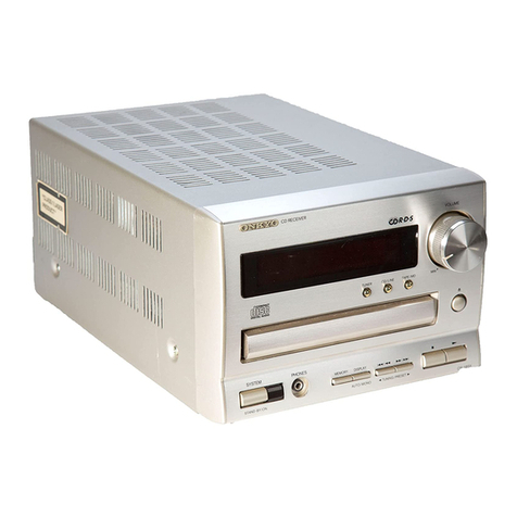
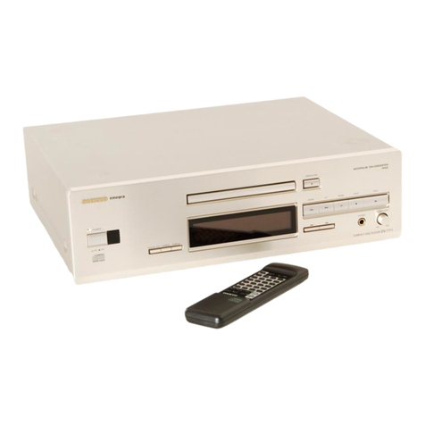
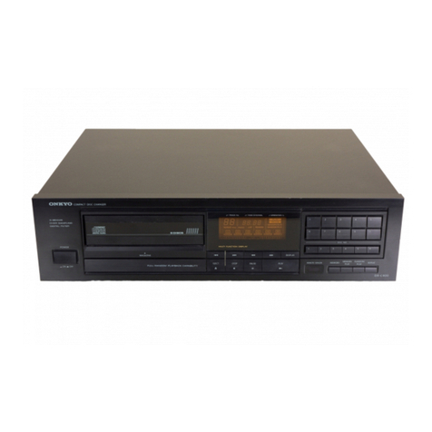
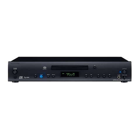
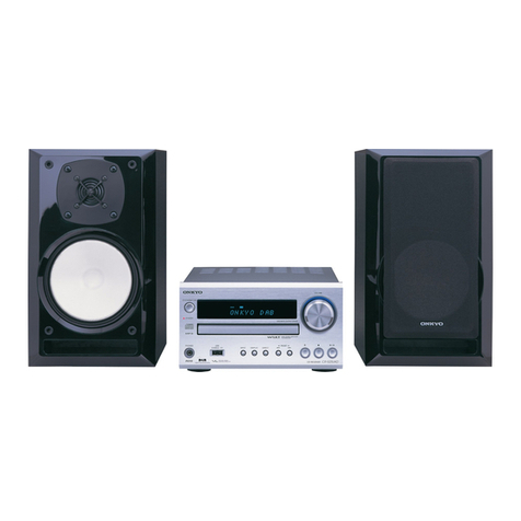
Onkyo DX-708 User manual

COMPACT
DIGITAL
AUDIO
Artistry
in
Sound
DX-
708/706
Compact
Disc
Player

e
Congratulations
on
your
purchase
of
the
ONKYO
DX-708/706
CD
Player.
©
Please
read
this
manual
thoroughly
before
making
connections
and
turning
power
on.
®@
Following
the
instructions
in
this
manual
will
enable
you
to
obtain
optimum
performance
and
listening
enjoyment
from
your
new
DX-708/706.
©
Please
retain
this
manual
for
future
reference.
FOATU
OS
ccc
cence
cnet
cette
t
eee
aueeceaesesaueecceeceeccessunnasecaesensaescureeerateveetstaieestrsttuttstetittetetyscetitsvititevesesecittneeteess
IMPOrtant
SAFEQUAIS
ooo...
ccc
ceccccccepecneccceseventuereeseeeeereeeceseduttateetdteersttssegettatteeeeceeesessebbetpiteiiieteverievenetrey
2
PRECAUTIONS
20
cece
cette
eect
bene
cere
teeeeeeeeeseecececevseasesuuarstesscessevensreseventieeentststeettiteteveiiteeverseeeerriteteteriieeveriiteneren
3
Before
using
this
Unita...
ccc
cece
ccc
cee
cre
ee
eesgee
tenet
cveeiesviassevrateveisegeiseseetesitatecistetrrsttveittverciysertitenrteees
3
SYSTEM
COMMECTIONS
20...
ccccecccccce
ee
ceneeceveneeeseneeesescueseeesureseveneriessutaeeeenestevnniestteescscteccrtteserttiteetrerietenttetes
4
Control
positions
and
MaMeSs
20.00.00
cccceccceee
cece
ee
ceeeeeeeeeeteessecuetesseseeeatereeasctteecetettetttteteee:
Leetiteeeeee
5
Handling
COMPAaCt
CISCS
0
cece
ccnee
scene
eceneveseetevriteennitedaatesaaesetesetitevttstctetecettitetttectetctttererneee,
6
COMMON
MOdE|S
Of
OPETAatION
o.oo
ccc
ceeeeeeeseeseveeseveeeseevessueessevessegeateseuteevictestsieevittestittetessecereeverene.
7
Using
the
Memory
function...
ccc
cccccccccccccveceececenereecentssevesssseseveestesestateevessseversisuseviitetettisecettisseeeerees
9
Functions
which
can
be
operated
only
by
using
the
remote
control
transmitter
.............0..0.....0.......
17
Using
the
remote
control
transmitter...
cccccceccceccececteeeeeneceveseeedateenesettcessteviettevitttevsscreeeecteseeree,
13
Troubleshooting
Quide@
ccc
ccccneececvensecceveaeesvenseevetaaeevesaesvesieaeesevtatesssessssesuveviteeetattetecceeseeetreeenes
14
SPECIFICATIONS
2c
ceeccee
cnt
eeeenecececcuvuedtenrateeevesteedntattviteteetesececete
pritiptrtititttiteteeseeteeritrteeesd
vevetveeeeeeeseares
Features
a
@
ONKYO
Single-Bit
D/A
Converters
instead
of
the
“muiti-bit”
D/A
converters
employed
in
many
CD
players,
the
DX-708
and
DX-706
use
an
innovative
“single-bit”
system.
It
does
away
with
the
jadder
network
required
by
conventional
“high-bit”
converters
and,
therefore,
needs
none
of
the
delicate
“trimming”
which
such
networks
require
to
achieve
even
adequate
linearity.
The
operating
principle
of
the
sing/e
bit
system
assures
far
better
linearity
than
conventional
D/A
converters
can
ever
achieve.
@
Zero
Shift
Noise
Shaper
The
noise
attenuation
characteristics
produced
by
the
digital
feedback
configurations
used
in
conventional
noise
shapers
are
marked
by
@
continuous
reduction
from
the
high
frequency
range
down
through
the
low
frequencies.
In
contrast
to
this.
ONKYO’s
new
Zero
shift
Noise
Shaper
employs
a
different
feedback
factor
to
produce
not
a
continuous
siope,
but
an
attenuation
pattern
in
which
noise
is
reduced
to
zero
in
the
middle
of
the
frequency
range.
The
practical
effect
of
this
modification
is
a
measurable
reduction
in
residual
noise
in
the
audio
frequency
range,
compared
with
con-
ventional
designs.
The
resulting
improvement
in
the
CD
player's
S/N
ratio
means
more
dynamic
music
reproduction,
allowing
the
listener
to
hear
delicate
nuances
which
might
have
been
missed
otherwise.
ONKYO’s
Zero
Shift
Noise
Shaper
heightens
the
smail
signal
fidelity
of
the
single-bit
D/A
conversion
process
for
improved
musicality
with
any
program
source.
®
Complementary
Distortion
Canceler
AccuPuise
Quartz
System
®
Center
Mounted
Disc
Tray
In
the
DX-708
and
DX-706,
the
central
location
of
the
disc
drive
mechanism
serves
to
divide
the
digital
and
analog
circuit
blocks
into
two
discrete
sections.
The
DX-
708
is
even
equipped
with
separate
power
supplies
for
the
two
sections,
offering
further
protection
against
mutual
interference.
This
arrangement
helps
to
prevent
DS}
(Digital
Signal
Interference)
from
leaking
into
the
analog
stage
and
also
contributes
to
improved
stability
for
the
chassis
as
whole.
Dual
AEI
Power
Transformers
(DX-708)
Newly
Developed
Linear
Motor
Actuator
for
Faster
Access
and
Better
Pickup
Precision
Diecast
Aluminum
Disc
Tray
Opto-Coupling
(DX-708)
Eight-Times
Oversampling
Digital
Filter
Peak
Search
Function
Facilitates
Making
Recordings
to
Cassette
Tape.
Optical
Digital
Output
Front
Panel
Dimmer
Switch
frRi
Compatible
Remote
Control!
Included
Copper
Plated
Chassis
(DX-708)
CAUTION
“WARNING”
“TO
REDUCE
THE
RISK
OF
ELECTRIC
SHOCK,
DO
NOT
REMOVE
“TO
REDUCE
THE
RISK
OF
FIRE
OR
ELECTRIC
SHOCK,
DO
NOT
COVER
(OR
BACK).
NO
USER-SERVICEABLE
PARTS
INSIDE.
EXPOSE
THIS
APPLIANCE
TO
RAIN
OR
MOISTURE.”
REFER
SERVICING
TO
QUALIFIED
SERVICE
PERSONNEL.”
Oy
pornos
@
For
models
having
power
cords
with
a
polarized
plug.
CAUTION:
to
PREVENT
ELECTRIC
SHOCK
DO
NOT
USE
THIS
(POLARIZED)
PLUG
WITH
AN
EXTENSION
CORD,
RE-
CEPTACLE
OR
OTHER
OUTLET
UNLESS
THE
BLADES
CAN
BE
®
The
lightning
flash
with
arrowhead
symbol,
within
FULLY
INSERTED
TO
PREVENT
BLADE
EXPOSURE.
an
equilateral
triangle,
is
intended
to
alert
the
user
to
the
presence
of
uninsulated
“dangerous
voltage”
within
the
product's
enclosure
that
may
be
of
suffi-
RISK
OF
ELECTRIC
SHOCK
DO
NOT
OPEN
@®
Sur
les
modéles
dont
Ja
fiche
est
polarisée.
cient
magnitude
to
constitute
a
risk
of
electric
shock
ATTENTIO
N:
POUR
PREVENIR
LES
CHOCS
ELECTRIQUES
to
persons.
NE
PAS
UTILISER
CETTE
FICHE
POLARISEE
AVEC
UN
PRO-
@
The
exclamation
point
within
an
equilateral
triangle
LONGATEUR,
UNE
PRISE
DE
COURANT
OU
UNE
AUTRE
SORTIE
is
intended
to
alert
the
user
to
the
presence
of
im-
portant
operating
and
maintenance
(servicing)
in-
DE
COURANT,
SAUF
Si
LES
LAMES
PEUVENT
ETRE
INSEREES
structions
in
the
literature
accompanying
the
apph-
A
FOND
SANS
EN
LAISSER
AUCUNE
PARTIE
A
DECOUVERT.
ance.
Important
safeguards
6A.
11.
12.
13.
14.
15.
16.
17.
.
Heed
Warnings
.
Water
and
Moisture
Read
Instructions
~~
All
the
satety
and
operating
instructions
should
be
read
before
the
appliance
is
operated.
Retain
Instructions
The
safety
and
operating
instructions
should
be
retained
tor
future
reference.
All
warnings
on
the
appliance
and
in
the
op-
erating
instructions
should
be
achered
to.
Follow
Instructions
~
All
operating
and
user
instructions
should
be
followed.
-
The
apphance
should
not
be
used
near
water
for
example,
near
a
bathtub,
washbow!),
kitchen
sink,
laundry
tub,
tn
a
wet
basement,
or
near
a
swimming
pool.
and
the
like.
Carts
and
Stands
The
appliance
should
be
used
only
with
a
cart
or
stand
that
is
recommended
by
the
manufacturer,
An
appliance
and
cart
combination
PORTABLE
CART
WARNING
should
be
moved
with
care.
Quick
stops,
excessive
force,
and
uneven
surfaces
may
cause
the
appliance
and
cart
combination
to
overturn.
@
Sass
vr
mah
~~
Wall
or
Ceiling
Mounting
—
The
appliance
shouid
be
mounted
to
a
wal!
or
ceiling
only
as
recommended
by
the
manufacturer.
Ventilation
-
The
appliance
should
be
situated
so
that
its
location
or
position
does
not
interfere
with
‘ts
praper
ventilation.
For
example,
the
appliance
should
not
be
situated
on
a
bed,
sofa,
rug.
or
similar
surface
that
may
block
the
ventilation
openings;
or,
placed
in
a
built-in
installation,
such
as
a
bookcase
or
cabinet
that
may
tmpede
the
flow
of
atr
through
the
ventilation
openings.
Heat
-
The
appliance
should
be
sttuated
away
from
heat
sources
such
as
radiators.
heat
registers.
stoves,
or
other
appliances
(including
amplifiers}
that
produce
heat.
Power
Sources
The
appliance
should
be
connected
to
a
powel
supply
only
of
the
type
described
in
the
operating
instructions
or
as
marked
on
the
appliance.
Polarization
—
If
the
appliance
is
provided
a
potarized
plug
having
on
blade
wider
than
the
other,
please
read
the
following
tnformation;
The
poiarization
of
the
plug
is
a
safety
feature.
The
polarized
plug
will
only
fit
the
outlet
one
way.
tf
the
plug
does
not
fit
fully
into
the
outlet,
try
reversing
it.
lf
there
is
still
trouble,
the
user
should
seek
the
services
of
a
qualified
electrician.
Under
no
circumstances
should
the
user
at-
tempt
to
defeat
the
polarization
of
the
plug.
Power-Cord
Protection
—
Power-supply
cords
shouid
be
routed
so
that
they
are
not
likely
to
be
walked
on
or
pinched
by
items
placed
upon
or
against
them,
paying
particular
attention
to
cards
at
plugs.
convenience
receptacles,
and
the
point
where
they
exit
from
the
ap-
pliance.
Cleaning
—
The
appliance
should
be
cleaned
only
as
recommended
by
the
manufacturer.
Nonuse
Periods
~
The
power
cord
of
the
appliance
should
be
unplugged
from
the
outiet
when
left
unused
for
a
jong
period
of
time.
Object
and
Liquid
Entry
-
Care
should
be
taken
so
that
objects
do
not
fal!
and
liquids
are
not
spilled
into
the
enclosure
through
openings,
Damage
Requiring
Service
—
The
appliance
should
be
serviced
by
qualified
service
personnel
when:
A.
The
power-supply
cord
or
the
plug
has
been
damaged;
or
B.
Qbjects
have
fallen,
or
liquid
has
been
spilled
into
the
appliance;
or
C.
The
appliance
has
been
expased
to
rain;
or
D.
The
appliance
does
not
appear
to
operate
normaily
or
exhibits
a
marked
change
in
performance,
or
E.
The
appliance
has
been
dropped
or
the
enclosure
damaged.
Servicing
-
The
user
should
not
attempt
to
service
the
appliance
beyond
that
described
tn
the
operating
instructions.
All
other
servicing
should
be
referred
to
qualified
service
personnel.
i)
SPECIAL
CAUTIONS
FOR
COMPACT
DISC
PLAYER
This
Compact
Disc
Player
contains
a
semiconductor
laser
system
and
is
classified
as
a
“CLASS
1
LASER
PRODUCT”.
So,
to
use
this
model
properly,
read
this
Owner's
Manual
carefully.
In
case
of
any
trouble,
please
contact
the
store
where
you
purchased
the
unit.
To
prevent
being
exposed
to
the
laser
beam,
do
not
try
to
open
the
enclosure.
The
laser
is
covered
by
a
housing
which
prevents
exposure
during
operation
or
maintenance.
However,
this
product
is
classified
as
a
Laser
Product
by
CDRH
(Center
for
Devices
and
Radio-
logical
Health)
which
is
a
department
of
the
Food
and
Drug
Administration.
According
to
their
regulations
2+
CFR
section
1002.30,
all
manufacturers
who
self
Laser
Products
must
maintain
records
of
written
communications
between
the
ma-
nufacturer,
dealers
and
customers
concerning
radiation
safety.
If
you
have
any
complaints
about
instructions
or
explanations
affecting
the
use
of
this
product,
please
fee
free
to
write
to
the
address
on
the
back
page
of
this
manua!.
When
you
write
us,
please
inciude
the
model
number
and
serial
number
of
your
Compact
Disc
Player.
In
compliance
with
Federal
Regulations,
the
certification,
identification
and
the
period
of
manufacture
are
indicated
on
the
rear
panel.
DANGER:
INVISIBLE
LASER
RADIATION
WHEN
OPEN
AND
iNTER-
LOCK
FAILED
OR
DEFEATED.
AVOID
DIRECT
EXPOSURE
TO
BEAM.
CAUTION:
THIS
PRODUCT
UTILIZES
A
LASER.
USE
OF
CONTROLS
OR
ADJUSTMENTS
OR
PERFORMANCE
OF
PROCEDURES
OTHER
THAN
THOSE
SPECIFIED
HEREIN
MAY
RESULT
IN
HAZARDOUS
RADIATION
EXPOSURE.
Notice
Concerning
FCC
Regulations
This
equipment
generates
and
uses
radio
frequency
energy
and,
if
not
installed
and
used
properly,
that
is,
in
strict
accordance
with
the
manufacturer's
instructions,
may
cause
interference
to
radio
and
television
reception.
|t
has
been
type
tested
and
found
to
comply
with
the
limits
for
a
Class
B
computing
device
in
accordance
with
the
specifications
tn
Subpart
J
of
Part
15
of
FCC
Rules,
which
are
designed
to
provide
reasonable
protection
against
such
interference
in
a
residential
installation.
However,
there
is
no
guarantee
that
interference
will
not
occur
in
a
par-
ticular
installation.
If
this
equipment
does
cause
interference
to
radio
and
television
reception,
which
can
be
determined
by
turning
the
equipment
off
and
on,
the
user
ts
encouraged
to
try
to
correct
the
interference
by
one
or
more
of
the
following
measures:
Reorient
the
recetving
antenna.
Relocate
the
unit
with
respect
to
the
receiver.
Move
the
unit
away
from
the
receiver.
Plug
the
unit
into
a
different
outlet
so
that
the
unit
and
receiver
are
on
different
branch
circuits.
lf
necessary,
the
user
should
consu!t
the
dealer
or
an
expertenced
radio/television
technician
for
additional
suggestions.
The
user
may
find
the
following
booklet
prepared
by
the
Federal
Com-
munications
Commission
helpful:
“How
to
identify
and
Resolve
Radio-TV
interference
problems."
This
booklet
is
available
from
the
U.S.
Government
Printing
Office,
Washington,
D.C.
20402,
Stock
No.
004-000-00345-4.
THIS
DIGITAL
APPARATUS
DOES
NOT
EXCEED
THE
CLASS
B
LIMITS
FOR
RADIO
NOISE
EMISSION
FROM
DIGITAL
APPARATUS
SET
OUT
IN
THE
RADIO
INTERFERENCE
RE-
GULATIONS
OF
THE
CANADIAN
DEPARTMENT
OF
COM-
MUNICATIONS.
L'INTERFERENCE,
RADIOELECTRIGQUE
GENEREE
PAR
CET
APPAREIL
NUMERIQUE
DE
TYPE
B
NE
DEPASSE
PAS
LES
LIMITES
ENONCEES
DANS
LE
REGLEMENT
SUL
LES
PER-
TURBATIONS
RADIOELECTRIQUES,
SECTION
APPAREIL
NUMERIQUE,
DU
MINISTERE
DES
COMMUNICATIONS.

Precautions
et
1.
Warranty
Card
4.
Care
The
serial
number
is
written
on
the
rear
panel
of
this
unit.
Copy
From
time
to
time
you
should
wipe
off
the
front
and
rear
panels
the
serial
number
and
model
number
onto
your
warranty
card
and
the
cabinet
with
a
silicon
or
other
soft
cloth.
For
heavier
and
keep
it
in
a
safe
place.
dirt,
dampen
a
soft
cloth
in
a
weak
solution
of
mild
detergent
and
water,
wring
it
out
dry,
and
wipe
away
the
dirt.
Following
this,
dry
immediately
with
a
clean
cloth.
Do
not
use
rough
material,
thinners,
alcoho!
or
other
chemica!
solvents
or
cloths
since
these
may
damage
the
finish
or
remove
the
panel
lettering.
2.
Do
Not
Touch
the
Player
with
Wet
Hands
Do
not
handie
the
player
or
power
cord
when
your
hands
are
wet
or
damp.
If
water
or
any
other
liquid
enters
the
player
cabinet,
take
the
player
to
an
authorized
service
station
for
inspection.
5.
Points
to
Remember
@
'f
the
player
is
brought
from
a
cold
environment
to
a
warm
one
or
Is
In
a
cold
room
that
is
quickly
heated,
dew
may
form
on
the
pickup,
preventing
proper
operation.
in
this
case,
remove
the
disc
and
leave
the
power
ON
for
about
one
hour
to
remove
the
dew.
@
Always
close
the
disc
tray
when
not
loading
or
unloading
discs
to
protect
delicate
internal
parts
from
dust.
@
When
transporting
the
player,
be
careful
not
to
bump
it
.
3.
Location
of
the
Player
@
Place
the
Player
in-a
Well-Ventilated
Location.
Take
special
care
to
provide
plenty
of
ventilation
on
all
sides
of
the
player
especially
when
it
is
placed
in
an
audio
rack.
If
ventilation
is
blocked,
the
player
may
overheat
and
mal-
function.
@
Do
not
expose
the
player
to
direct
sunlight
or
heating
units
as
the
player's
internal
temperature
may
rise
and
shorten
the
life
of
the
pickup.
@®
Avoid
damp
and
dusty
places
and
places
directly
affected
by
vibrations
from
the
speakers.
In
particular,
avoid
placing
the
unit
on
or
above
one
of
the
speakers.
®
Be
sure
the
player
is
placed
in
a
horizontal
position.
Never
place
it
on
its
side
or
on
a
slanted surface
as
it
may
mal-
function.
@®
Do
Not
Place
Near
Tuners
and
TV
Sets.
lf
placed
next
to
a
TV
or
other
tuner,
it
may
cause
reception
interference
resulting
tn
some
noise
in
the
TV
or
tuner
output.
Before
using
this
unit
a
How
to
Release
the
Transport
Lock
To
protect
the
optical
assembly
including
the
laser
pickup
from
vibration
related
damage
during
shipping,
this
unit
is
equipped
with
a
transport
lock
lever
located
on
the
base.
1.
Loosen
the
screw
with
a
Phillips
screwdriver.
Phillips
screwdriver
2.
Move
the
lock
lever
in
the
oppositte
direction
to
that
shown
e3-
Lock
lever
screw
hole
move
no
farther.
fo?
by
the
arrow.
Move
the
lever
up
to
the
position
where
it
can
LP
Then
re-tighten
the
screw
into
lock
lever
screw
hole.
wo
B@
Tighten
the
screw
to
secure
the
lock
lever.
®
For
shipping,
turn
the
lock
lever
to
its
position
in
the
direction
of
the
arrow,
then
tighten
down
the
screw
ta
secure
the
lock
lever
in
that
position.
Lock
fever
Supplied
accessories
Remote
control
transmitter
RC-217C
(DX-706)
x
1
Output
signal
cord
x
1
f21
remote
control
cable
x
1
RC-218C
(DX-708)
x
1
Battery
x
2

System
connections
a
@
Do
not
plug
in
the
power
cord
until
all
connections
have
been
made.
@
This
unit
has
two
sets
of
analog
OUTPUT
jacks
and
a
DIGITAL
OUTPUT
jack.
ONHYO.,
MABE
faa
EL
ROE
MOGEL
NC
Optical
fiber
cable
Output
signal
cord
CPTICAL
Speaker
Integrated
Amplirfier
Connecting
to
the
analog
OUTPUT
jacks
®
Connect
the
OUTPUT
jacks
of
this
unit
to
the
AUX
or
CD
input
jacks
of
an
amplifier.
When
making
connections,
be
sure
that
the
left
and
right
channel
connections
are
not
crossed.
@
This
unit
is
equipped
with
two
OUTPUT
jacks,
FIXED
and
VARIABLE.
Use
the
one
that
matches
your
purpose.
Connecting
digital
signals
(DIGITAL
OUTPUT)
@®
This
unit
has
a
digital
audio
interface
format
digital
jacks
for
optical
output.
NOTE:
The
optical
digital
output
jack
has
a
protective
cap.
Remove
this
cap
before
using
this
jack.
When
not
using
this
jack,
always
put
this
protective
cap
back
on
the
jack.
Remete
control
cable
AC
POWER
SUPPLY
CORD
*
To
FRI
remote
control
jack
of
the
ONKYO
receiv-
ers,
amplifiers
or
cassette
tape
decks.
*
The
upper
and
lower
RI
remote
control
jacks
have
the
same
function.
Speaker
Remote
Control
jacks
The
remote
control
jacks
are
used
to
connect
ONKYO
products
bearing
the
”
(QI
”
mark
via
the
accessory
remote
control
cable.
The
cassette
deck
with
the
“
FRI”
mark
can
be
operated
using
the
RC-217C/218C
remote
control
transmitter
provided
as
an
accessory
with
the
DX-706/708.
When
this
unit
is
connected
with
ONKYO
receivers
or
amplifiers
bearing
the
~
fR4
“
mark,
it
can
also
be
controlled
by
the
remote
contral
transmitter
of
that
unit.
(Refer
to
the
operating
instructions
of
your
stereo
receiver
or
amplifier
for
details.)
NOTE:
Do
not
connect
the
FRI
remote
control
jack
to
any
unit
that
does
not
bear
the
ONKYO
“
FRI”
mark.
Doing
so
may
damage
the
unit.
Using
the
timer
during
performance
Amolifier
ef
output
Timer
signal
cord
e;
DX-708/706
a
TT
To
AC
outlet
If
you
have
an
audio
timer,
it
can
be
used
to
start
a
performance
at
any
time
you
desire.
Q)
Turn
on
the
DX-708/706
and
the
amp
which
ts
connected
to
the
DX-708/706.
2)
Insert
a
compact
disc
into
the
DX-708/706
disc
tray.
(3)
Set
the
time
on
the
timer.
@
For
more
details,
please
consult
the
section
which
explains
the
operations
of
the
timer.
@
When
the
time
specified
arrives,
the
CD
player's
auta-play
function
will
begin
the
performance
automatically.

Control
positions
and
names
a
Front
panel
For
more
information
about
buttons
or
controls,
turn
to
the
page
number
listed
in
the
[
|.
6)
Cl
Butt
PEN/CLOSE
4
Power
Switch
(POWER)
[7]
pen/Close
Button
(OPEN/CLOS
7)
(~
Elapsed/Remaining
Time
Button
(ELAPSED/REMAIN)
[7]
a
Repeat
Button
(REPEAT)
[8]
Remote
Control
Sensor
[13]
la
Stop
Button
(STOP
#
)
[7]
Disc
Tray
[7}
Pause
Button
(PAUSE
tt
)
[7}
Display
Piay
Button
(PLAY
»P
)
[7]
la
Up
Button
(UP
Pi
)
[8]
Number
Buttons
(1
~9,
0)
and
Plus
Ten
Button
(+10)
[8,
9,
10]
Down
Button
(DOWN
Kee
)
[8]
Display
Switch
(DISPLAY)
[7]
Fast
Forward
Button
(FF
p®
)
[8}
\——
Level
Control
Knob
Fast
Reverse
Button
(FR
<<
)
[8]
(OUTPUT
LEVEL)
[7]
\.
Headphone
jack
Memory
Button
(MEMORY)
[9]
Clear
Button
(CLEAR)
[9]
(PHONES)
(MEMORY
REVERSE)
[10]
Display
Function
Display
_
a
oe
a
__
-
a
.
(2
Le
LL
LL
Le
eee
eee
|
[fore
ES
MARIA
bh
vB
BI
RE
PE
AT
Ab
SHINEE
EMPHASES
Ith
t
DU
PAUSE
J
[PEAK
SEARCH}
‘
|
TE
\_
ADE
AospaE
Piha
we
ty,
nT
—
—
hi
v0
Th,
IERAG
«TIMI
POT
AL
GnSc
7
IMI
|!
LI
Pf
gf
crapsen
ff
Li
cL
Lo
trapses
=
LA
LE
I
LI
|
|
i
|
ff
if
EMAIN
ff
Ee
hd
Ld
HE
MAIN
if
ff
ff
tf
|
em
mmm
nme
ns
—.-—
-oee
—
—
=a
7
7
Track
Number
Display
Track
Time
Display
Number
Display
Total
Dise
Time
Display

Remote
control
transmitter
RC-218C
(RC-217C)
®
Buttons
not
described
below
are
operated
in
the
same
way
as
the
buttons
on
the
main
unit.
Open/Close
Button
(
4A
)
[7]
CD/TAPE
Selector
Switch
This
switch
should
normally
be
set
to
CD/Tape
Operation
Buttons
the
CD
side.
When
a
cassette
deck
When
the
CD:’TAPE
selector
switch
|s
bearing
the
ONKYO
“
FRE”
mark
is
cn
CD.
[7,
8)
connected
to
the
remote
control
jacks
m=
Stop
Button
of
the
DX-
708/706
model,
the
deck
can
pe.
Play
Button
be
controlled
by
this
remote
contro!
tu
Pause
Button
transmitter.
Set
the
CD/TAPE
selector
440
Fast
Reverse
Button
(oT
EV
EY
switch
to
TAPE.
At
this
setting,
the
6
pe
-
Fast
Forward
Buttor
==
=)
J
|
functions
(from
™@
to
Pm
)
listed
at
left
tq
Down
Button
TT
oS
can
be
operated
by
remote
control.
la
fo).
When
the
CD;TAPE
selector
switch
1s
=)
a
|
Oo)
a
on
Tape
;
—=>
Shuffle
Button
(SHUFFLE)
[11]
r
Cc
@®
Stop
Button
om
a
eee
@/n
>
Rec.’
Pause
Button
>
Clear
Button
(CLEAR)
[9]
44.
Fast
Rewind
Button
—J>
oo
QQ
pe
Fast
Forward
Button
QgOqQaaoo
4
Reverse
Play
Button
Number
Buttons
and
Plus
Ten
»
Forward
Play
Button
~WMoo
ca
Button
(8,
9,
10]
Memory/Memory
Reverse
Button
oe
eee
|
‘a
(AUTO
SPACE)
[11]
(MEMORY/REVERSE)
[9,
10]
=
|
~>
=
—(Ri]
Fade
Out
Button
(FADE)
[11]
Eiapsed/Remaining
Time
Button
|
|
(
3
||
a
|
(ELAPSED/REMAIN)
[7]
ON
Volume
Control
Buttons
(o)\(),)
as
|
(VOLUME
DOWN/UP)
IR]
Peak
Search Button
;
i‘
:
Press
DOWN
button
to
lower
the
volume
(PEAK
SEARCH)
[12]
level
output
from
the
variabie
output
jacks
and
headphone
output
jacks,
and
Repeat
Button
(REPEAT)
[8]
press
UP
button
to
increase.
It
works
the
same
as
the
OUTPUT
LEVEL
knob
on
-
706.
FRI,
Block
Repeat
the
DX-708/706
Button
(A-B)
(11,
12]
Time
Edit
Button
(TIME
EDIT)
[12]
®
The
buttons
shown
with
the
Al
mark
in
the
iiustration
above
control
functions
which
can
only
be
accessed
using
the
remote
control
transmitter.
®
The
only
difference
between
the
RC-217C
madel
and
the
RC-218C
model
is
the
Number
Buttons.
Both
remote
contro!
transmitters
can
control
the
same
functions.
Handling
Compact
Discs
TST
tiow
to
open
a
disc
case
and
remove
a
disc.
®
Always
handle
compact
discs
with
care
so
that
they
are
not
ae
.
:
scratched,
soiled
or
damaged.
9
®
Aadry
soft
cloth
may
be
used
to
wipe
cust,
fingerprints,
etc
“y
off
the
surface.
@
Make
absolutely
sure
not
to
use
any
type
of
volatile
agent,
such
as
thinner
or
benzine.
Also
avoid
using
a
conventional
record
«
cleaner
or
antistatic
agent.
@
Avoid
placing
a
dise
in
direct
sunlight,
and
locations
subject
to
extremely
high
humidity
or
low
temperature.
®
When
adisc
ts
going
to
be
left
unused
for
a
long
period
of
time,
be
sure
not
to
leave
it
in
the
player
but
store
it
in
the
case.
—_
oO

Common
modes
of
operation
To
Load
and
Play
a
Disc
(Normat
Play)
(3)
Disc
Tray
(2)(4)
OPEN/CLOSE
4
(7)
STOP
&
(6)PAUSE
II
(5)
PLAY
>
OUTPUT
LEVEL
(>
Press
the
POWER
switch
to
turn
on
the
power.
(2)
Press
the
OPEN/CLOSE
A
button
to
open
the
Disc
Tray.
(3.
Put
the
disc
in
the
Disc
Tray
with
its
label
facing
up.
(4;
Press
the
OPEN/CLOSE
4
button
again
to
close
the
disc
tray.
'
@
The
disc
is
ready
for
play
when
the
following
indications
appear
on
the
display.
When
the
number
of
iracks
exceeds
20.
the
OVER}indicator
hghts
z
HOTA
La
ay
a.
|
|
.
a
~~
|">
—
i
a
on
ae
TEE
MAIS
_/
=]
_
("7
mr ta
7
*
~~
HL
MAY
Thy
The
total
number
of
tracks
on
the
disc
The
total
playing
time
of
the
disc
®
Ifnothing
ts
displayed,
this
may
mean
that
the
disc
is
in
upside
down.
If
that
is
the
case,
take
out
the
disc
and
put
it
in
right
side
up.
(5)
Press
the
PLAY
Pb
button.
@®
The
disc
begins
playing
trom
the
first
track.
@
When
you
put
the
disc
in
the
disc
tray,
if
you
press
the
PLAY
>
button
instead
of
the
CPEN/CLOSE
4
button,
the
tray
is
closed
automatically
and
the
first
track
begins
to
play.
luminated
when
playing
the
track
which
contains
emphasis
—
“am.
aa
:
Aan
Die
—
It
_/
Next
track
number
The
total
playing
time
which
has
elapsed
from
the
start
of
The
current
ack
number
play
The
elapsed
playing
time
for
the
track
that
is
playing.
@
After
a
disc
is
played
all
the
way
to
the
end,
the
display
resets
to
the
initial
condition
when
the
disc
is
toaded.
DISPLAY
~~]
ELAPSED/REMAIN
(6)
Press
the
PAUSE
«§
button
to
stop
the
performance
tempo-
rarthy.
®
The
PAUSE
indicator
lights
and
the
playing
stops
temporarily.
®
Toresume
playing,
press
the
PLAY
P
button.
The
playing
Starts
up
again
from
exactly
where
it
left
off.
(7)
To
stop
the
playing,
press
the
STOP
™
button.
NOTE:
|
The
DX-
708/706
has
an
auto-ptay
function.
If
a
disc
has
already
been
inserted
when
the
power
is
turned
ON,
performance
wil!
vegin
automatically.
BH
Volume
adjustment
Use
the
OUTPUT
LEVEL
knob
to
adjust
the
output
ieve!
(VARIABLE)
and
headphone
output
level.
@
To
change
the
display
Press
the
ELAPSED/REMAIN
button
ta
see
the
elapsed
time
(ELAPSED)
on
the
FRACK
TIME
as
well
as
the
TOTAL
DISC
TIME.
Press
it
again
to
see
the
remaining
time
(REMAIN)
on
both
displays.
TRACK
TIME
ELAPSED:
Displays
the
elapsed
time
of
the
current
track.
REMAIN:
Displays
the
remaining
time
of
the
current
track.
TOTAL
DISC
TIME
ELAPSED:
Displays
the
total
elapsed
time
from
the
beginning
of
play.
REMAIN:
Displays
the
tota!
remaining
time
until
the
end
of
play.
During
memory
play,
this
display
shows
the
playing
time
re-
maining
for
the
entire
sequence
of
tracks
programmed
into
memory.
NOTES:
@
For
a
track
beyond
the
20th,
TRACK
TIME
display
shows
@
if
the
Total
Remaining
Time
is
more
than
99
minutes
59
seconds,
the
TOTAL
DISC
TIME
display
shows
“—
~:
----”.
@
To
change
the
brightness
of
the
display
The
DISPLAY
switch
can
be
used
to
change
the
brightness
of
the
display.
@®
OFF:
Turns
the
display
completely
OFF.
When
carrying
oul
a
button
operation,
the
display
wil!
appear
for
a
few
seconds,
then
disappear
again.
@®
NORMAL:
Norma!
brightness
@
DIM:
Dimmer
than
norma....this
can
be
used
when
the
display
is
too
bright
relative
to
the
lighting
in
the
room

To
strat
from
a
specific
track
OON
HOW)
Trite-ciad
Number
Buttons
and
+10
Button
Using
the
Number
Buttons
to
select
the
desired
track
(Direct
Play).
@
Use
+10
button
to
select
a
track
with
a
track
number
of
10
or
higher.
For
example,
to
select
Track
Number
30,
press
this
button
three
times,
and
then
press
O.
Td
J]410
~~
.
=
ese)
To
move
forward
or
backward
quickly
during
playing.
ONBR
WO
Hitlers
FR<4<4,
FF
>>
Press
the
FF
b®
button
to
fast
forward.
Press
the
FR
#4
Dutton
to
fast
backward.
@
The
pickup
continues
to
move
rapidly
forward
or
backward
as
long
as
you
hoid
down
the
FF
P»®
button
or
FR
#4
button.
®
if
you
fast
forward
all
the
way
to
the
end
of
the
disc,
the
pickup
Stops.
@
During
memory
play,
when
the
pickup
is
forwarded
to
the
end
of
the
current
track
by
pressing
the
FF
»®
button.
the
pickup
comes
to
the
next
programmed
track
and
normal
playback
be-
gins.
When
the
FR
¢#€
button
is
pressed,
the
pickup
comes
to
the
beginning
of
the
current
track
and
narma!
playback
begins
from
this
position.
To
return
to
the
beginning
of
the
track
during
playing
or
to
skip
to
the
next
track
COON
HW)
ited
d
DOWN
Ke<d)
UP
P|
To
skip
to
the
next
track,
press
the
UP
button.
®
The
playing
of
the
current
track
is
tnterrupted
and
the
pickup
moves
to
the
beginning
of
the
next
track.
During
memory
play
the
pickup
moves
to
the
beginning
of
the
next
track
in
memory.
@
The
pickup
moves
ahead
one
track
each
time
you
press
the
UP
pr)
Dutton.
To
return
to
the
beginning
of
the
track
during
ptaying,
press
the
DOWN
ke
button.
®
The
playing
ts
interrupted
and
the
pickup
moves
back
to
the
veginning
of
the
current
track.
@
if
you
press
the
DOWN
Ke
button
again
before
the
pickup
reaches
the
beginning
of
the
current
track
or
you
press
the
DOWN
Ke
button
twice
in
a
row.
the
pickup
goes
to
the be-
ginning
of
the
previous
track.
During
memory
play
the
pickup
goes
to
the
beginning
of
the
preceding
track
in
memory.
To
listen
to
the
tracks
over
and
over
COON
HWE)
[rer
REPEAT
®
To
repeat
performance
of
the
disc
being
used
Press
the
REPEAT
button.
(You
can
press
this
button
before
playing
begins
or
in
the
middie
of
playing.)
The
REPEAT
indicator
lights
and
when
the
playing
reaches
the
end
of
the
disc.
it
starts
again
from
the
first
track.
®
During
memory
piay
when
the
performance
reaches
the
end
of
the
sequence
of
tracks
pragrammed
into
memory
it
repeats
that
sequence.
@®
To
stop
the
repeat
play.
press
it
again.

Using
the
Memory
function
To
program
and
play
the
memory
ONEY®O
Integra
(3)PLAY
>
(2)
Number
Buttons
and
+10
Button
(1)
Press
the
MEMORY
button.
@®
The
MEMORY
indicator,
MEMORY
No.
indicator
will
light.
lf
the
MEMORY
button
ts
pressed
during
play,
the
track
being
played
is
stored
into
memory
and
further
tracks
can
be
stored
into
memory
with
the
operation
in
(2)
below.
(2
Select
the
track
you
want,
using
the
Number
Buttons
and
+10
Button.
Example:
Memorizing
track
number
4
in
memory
channel
1
The
selected
track
number.
The
playback
time
for
the
selected
track.
Memory
channel
Tie
total
play
time
of
selected
tracks
®
To
continue
programming
the
memory,
enter
the
number
of
the
next
selection
to
be
programmed.
Up
to
20
tracks
can
be
programmed
in
the
memory
by
repeating
this
step.
If
attempting
to
program
more
than
20
tracks
in
the
memory,
i
will
flash
a
few
times
on
the
MEMORY
No.
display
to
indicate
that
the
memory
is
full.
(1)
MEMORY
(3:
Press
the
PLAY
P
button.
@
Play
begins
in
the
programmed
order.
@
The
display
below
is
shown
between
tracks
(or
during
the
search
process).
i_i
-
ri
in!
bh
ae
ns
beeen
Memory
channel
Next
track
number
in
the
rnemory.
@
The
display
below
is
shown
during
playing.
The
number
of
the
track
currently
being
played
Next
track
number
in
memary
Time
elapsed
tn
track
currently
playing
Total
elapsed
time
To
check
the
contents
of
the
memory
1.
If
in
memory
play,
press
the
STOP
@
button
so
that
the
play
comes
to
a
memory
Stop.
@
The
last
track
number
and
its
memory
channel
will
appear
on
the
TRACK
No.
display
and
the
MEMORY
No.
display.
2.
Press
the
FR
<4
or
FF
pb
button.
To
cancel
the
contents
of
the
memory
Press
the
CLEAR
button.
@®
The
last
track
in
memory
will
be
cancelled.
@
During
memory
play,
the
current
track
In
play
and
tracks
previ-
ously
programmed
cannot
be
cancelled.
@
Press
the
MEMORY
button
when
the
contents
have
been
completely
erased
at
one
time.
During
memory
play,
however,
normal
play
takes
place,
playing
the
current
through
the
last
tracks.
—
J
—

To
use
the
Memory
Reverse
Function
This
function
excludes
the
tracks
from
the
memory,
and
programs
other
tracks
on
the
disc.
For
exampie,
:f
10
out
of
15
tracks
on
the
disc
are
to
be
programmed
in
the
memory,
five
unwanted
tracks
can
be
excluded,
instead
of
programming
10
other
tracks.
The
function
is
nat
activated
during
playback.
ONHKYO
Integra
(2)
Number
Buttons
and
+10
Button
4°
Press
the
MEMORY
button.
(MEMORY
indicator
will
light.)
.
Program
unwanted
tracks
by
pressing
the
corresponding
number
buttons.
@
Five
unwanted
tracks.
for
exampie
3,
7.12,
13
and
15
are
programmed
in
the
memory.
aN
“3
Press
the
MEMORY
button
again.
(The
REVERSE
indicator,
as
well
as
the
MEMORY
indicator,
will
light.)
@
The
tracks
are
stored
into
memory,
except
the
ones
which
have
already
been
programmed
in
step
(2)
|
~.,
~.
~
ae
Lan
|">~
.
~
al
~~
+.
—
|->~
ae
4
The
tracks
which
have
not
been
programmed
will
be
memorized
in
numerical
order
automatically.
(3)
MEMORY
REVERSE
NOTES:
@
if
there
are
more
than
20
tracks
which
have
not
been
pro-
grammed,
as
many
as
20
tracks
will
be
memorized
from
the
smaller
number.
@
To
cance!
the
Memory
Reverse
mode,
press
the
MEMORY
button
again.
The
first
time
the
MEMORY
button
in
oressed
the
MEMORY
mode
is
initiated,
the
second
time
switches
to
MEMORY
REVERSE
and
the
third
time
cancels
the
memory
mode.
IO

Functions
which
can
be
operated
only
by
using
the
remote
control
transmitter
ee
To
playback
in
random
order
(Shuffle
Play)
SHUFFLE
AUTO
SPACE
LCOCCCC!
CULLLLI
Press
the
SHUFFLE
button.
@
When
this
button
is
pressed,
the
SHUFFLE
indicator
lights
up
and
the
Auto
Space
function
wil!
insert
4
seconds
af
blank
time
between
tracks
during
Shuffle
play.
Performance
automatically
begins.
@
This
function
can
be
used
in
memory
mode.
In
this
case,
the
programmed
tracks
are
played
at
random.
NOTES:
@
Inthe
Shuffle
Play
Repeat
mode,
when
ail
of
the
tracks
have
been
played
back
once,
the
order
will
be
changed
and
the
playing
will
be
repeated
with
a
different
track
progression.
@®
The
SHUFFLE
mode
will
be
cancelled
when
the
SHUFFLE
button
is
pressed
again,
or
when
ail
of
the
tracks
have
been
played
back
and
stopped.
Press
the
AUTO
SPACE
Button
to
switch
the
auto
space
function
on
and
off.
When
the
auto
space
function
is
operating,
the
AUTO
SPACE
indicator
lights
and
a
blank
space
lasting
4
seconds
is
in-
serted
between
tracks.
To
use
the
Fade
Out
Function
(FADE)
This
function
gradually
decreases
the
volume.
Set
the
volume
knob
to
the
maximum
ievel
first.
Press
the
FADE
button
during
performance.
@
Volume
will
decrease,
with
the
FADE
indicator
flashing.
®
The
volume
becomes
minimum
in
approx.
10
secands,
and
the
performance
will
be
stopped.
@
This
function
is
effecttve
on
the
PHONES
or
VARIABLE
OUT-
PUTS.
To
repeat
the
block
specified
(Block
Repeat)
a
wu
4
Bio,
o1Q)
0/0
Vioajolo
ii
To
set
the
beginning
and
ending
paints
of
the
block,
press
the
A-B
button
during
playing.
Press
once
at
the
beginning
of
the
block
repeat
(point
A)
(block
repeat
indicator
(A-B)
flashes)
and
once
again
at
the
end
of
the
biock
repeat
(pornt
B)
(block
repeat
indicator
remains
lit).
The
section
between
A
and
B
ts
played
repeatedly.
The
ending
point
must
be
at
a
disc
location
after
the
starting
po:nt.
To
cancel
the
block
repeat,
press
the
A-B
button
once
mere.
Disc
play
will
then
continue
until
the
end
of
the
disc.
NOTE:
It
is
not
possibile
to
use
the
block
repeat
function
during
memory
play,
shuffle
play,
memory
shuffle
play
and
repeat
play.

This
function
searches
for
the
peak
volume
through
the
disc.
(PEAK
SEARCH)
4
ow
PEAK
SEARCH
A-B
Depending
on
the
disc
in
play,
memorizing
of
a
level
which
is
different
from
the
maximum
audible
level
could
occur.
This
is
due
to
the
CD
player’s
microprocessor
memorizing
inaccurate
infor-
mation
because
of
flaws
in
the
disc
itself,
or
recording
conditions.
Under
such
circumstances,
the
recording
level
for
the
cassette
tape
may
be
entirely
low,
or
else
distortion
or
similar
symptoms
could
arise
on
account
of
excessively
high
signal
inputs.
To
avoid
this,
be
sure
to
reset
the
recording
level
of
the
cassette
deck
in
accordance
with
the
symptoms.
Press
the
PEAK
SEARCH
button.
®
The
player
checks
the
disc
for
level.
The
PEAK
SEARCH
indicator
will
flash
during
this
operation.
After
checking,
the
-
indicator
will
light.
Press
the
A-B
button.
@
The
A-B
indicator
will
fight
and
°°
will
flash
on
the
ME-
MORY
No.,
NEXT
No.
display.
Press
the
PLAY
Pb
button.
®
Part
of
the
track
with
the
largest
volume
on
the
disc
will
be
played
repeatedly
for
6
seconds.
®
Refer
to
this
level
when
recording
the
disc
onto
the
cassette
tape.
Press
the
STOP
@
button
to
stop
performance.
Repeat
steps
2
and
3
to
adjust
the
level
again.
@
This
level
is
memorized
until
the
OPEN/CLOSE
4
button
is
pressed
or
the
power
is
turned
off.
@
Pressing
the
PEAK
SEARCH
button
will
turn
off
the
indicator
and
the
level
will
be
released
from
the
memory.
@
Pressing
the
A-B
button
after
pressing
the
PLAY
P»
button
for
performance
will
start
the
A-B
repeat
operation.
To
use
the
Time
Edit
Function
@
This
function
ts
convenient
for
recording
and
editing
tapes.
@®
Stop
the
playback,
and
cancel
the
memory,
!f
necessary.
TIME
EDIT
1.
Press
the
TIME
EDIT
button.
@
TIME
EDIT
indicator
will
flash
and
the
TRACK
TIME
will
display
C:
—
—.
2.
Specify
the
tape
fength
on
the
“C:
—
—”
section
using
the
+10
butten
and
the
Number
buttons.
For
example,
to
input
“46”,
press
the
+10
button
4
times
and
then
press
the
Number
button
"6".
Press
the
STOP
button
and
Start
the
procedure
from
the
beginning
when
the
tape
size
has
been
input
by
mistake.
Pressing
the
UP
ppy
or
DOWN
Ke
button
will
carry
out
adjustment
by
one
minute.
@
Automatic
calculation
of
the
number
of
tracks
entered
on
the
A
and
B
sides
begins.
The
order
ts
the
order
in
which
the
tracks
are
entered
on
the
disc.
@
After
calculating
the
recording
track
times,
the
MEMORY
No.
and
NEXT
No.
display
will
be
changed
fram
(for
example)
Fe-.
Bb
-.
4
to
&
-.
These
itliuminate
in
order.
Also
a
number
will
be
displayed
to
show
how
many
tracks
can
be
recorded
on
each
side
of
the
tape
(A
and
B).
—
ne
4
-
i
i
oy!
-
-
= -
-
-_
a
on
[ae
toed
torres
a
|
‘at
crn
a
ioe
it
7
fps
=}
|
bean
eee
Joo
ee.
=
—
The
last
track
on
sicte
A.
The
total
time
of
the
tracks
on
side
A.
The
total
track
on
side
A.
®
When
you
want
to
add
tracks,
select
one
from
either
side
by
pressing
the
ELAPSED/REMAIN
button
and
the
track
will
be
added
at
the
end
of
the
tracks
which
you
have
already
selected.
If
no
other
tracks
will
fit
on
the
tape,
the
indicator
will
flash
3
-
4
times,
indicating
that
no
more
tracks
can
be
added.
®
Press
the
TIME
EDIT
button
again
to
minimize
the
empty
space
on
the
tape.
The
TIME
EDIT
indicator
will
light
and
the
micro
computer
will
automatically
arrange
the
order
of
the
tracks.
A
total
of
up
to
20
tracks
can
be
recorded
on
side
A
and
B.
If
along
tape
is
used,
empty
space
may
be
left
even
after
20
tracks
have
been
recorded.
Checking
the
tape
size
and
total
disc
time,
and
utilizing
this
function
will
optimize
the
edit
conditions.
@
The
contents
of
the
TIME
EDIT
can
be
checked
by
pressing
FR
@4
or
FF
®®
buttons,
following
the
same
procedure
as
checking
the
contents
of
the
memory.
You
can
check
which
CD
track
number
has
been
programmed
in
a
certain
tape
track
number,
by
pressing
either
FR
«4
or
FF
®®
buttons.
When
the
contents
of
the
A
side
end,
the
contents
of
the
B
side
will
then
be
automatically
displayed.
Press
the
PLAY
p
button.
When
playback
of
the
last
track
on
side
A
is
completed,
the
pause
mode
is
set
automatically.
@
Press
the
PLAY
PF
button
to
start
playback
agatn.
The
pause
mode
Is
canceled
and
side
B
plays.
@
TIME
EDIT
will
be
cancelled
when
recording
on
both
sides
has
been
finished
or
the
STOP
™
button
is
pressed.
NOTE:
The
time
edit
mode
does
not
function
for
discs
with
more
than
20
tracks
recorded
on
them,
or
when
the
first
track
is
longer
than
half
of
the
indicated
time.

Using
the
remote
control
transmitter
ee
1.
Remove
the
batteries
if
the
remote
control
transmitter
1s
not
going
ta
be
used
for
a
jong
time.
2.
The
batteries
of
the
remote
contro!
transmitter
must
be
repiaced
periodically.
3.
This
untt
uses
infrared
rays.
Therefore,
commands
may
not
be
received
properly
if
the
front
panei
of
this
unit
is
exposed
to
bright
light.
To
prevent
this
from
occurring,
place
this
unit
so
that
it
is
not
directly
exposed
to
bright
light.
4.
lf
this
unit
is
placed
inside
an
audio
rack
behind
a
glass
door,
the
door
should
not
have
colored
glass
or
have
any
decorations
on
it,
since
thts
could
shorten
the
range
or
prevent
commands
from
being
received.
5.
Use
of
other
infrared
remote
control
devices
in
the
same
room
may
cause
interference.
6.
The
transmitter
operates
up
to
a
distance
of
about
five
meters
(16
feet).
The
transmitting
window
must
always
be
pointed
at
the
reception
window
wher
a
command
is
sent
to
the
CD
player.
7.
If
this
remote
controi
transmitter
does
not
operate
properly,
confirm
that
the
batteries
are
not
dead.
If
the
probiern
persists,
contact
your
ONKYO
Service
Center.
Transmitter
Battery
Insertion
CD)
Push
the
battery
cover
on
the
rear
of
the
transmitter
in
the
di-
rection
of
the
arrow
and
lift
it
up.
(2)
Load
the
two
batteries
that
came
with
the
transmitter
or
two
batteries
listed
in
the
table.
Load
them
with
the
+
and
—
ends
facing
as
shown
tn
the
diagram.
(3.
Put
the
battery
cover
back
in
place.
DX-
706/708
Remote
sensor
|
|
~
approx.
5m
a
é
(16
feet)
4
:
“
Remote
control
transmitter
RC-217C/218C
Use
of
Batteries
@
The
remote
contral
transmitter
is
powered
by
two
batteries.
Before
using
this
unit
for
the
first
time,
insert
the
two
batteries
(included)
as
shown
in
the
diagram.
@
Average
battery
life
is
about
one
year.
This
period
may
be
shorter
depending
on
the
frequency
of
use
and
environment
({temper-
ature
and
humidity)
in
which
the
remote
control
transmitter
ts
used.
@®
|f
the
remote
contro/
transmitter
does
not
operate
even
though
front
panel
controis
function
normally,
the batteries
should
be
repiaced.
Use
only
batteries
listed
in
the
following
chart.
Type
Do
not
feave
an
expired
battery
in
the
case
as
It
may
leak
or
damage
the
battery
case.
When
inserting
the
batteries,
be
sure
the
(+)
and
(-)
ends
are
properly
aligned.
Do
not
use
nickel-cadmium
(rechargeable)
batteries.
Do
not
use
one
specified
(manganese)
battery
and
one
al-
kaline
battery
at
the
same
time.
Replace
both
batteries
at
once;
do
not
use
one
old
and
one
new
battery
together.

Troubleshooting
guide
not
come
on.
Skipping.
track}
Is
extremely
long.
memory.
Specifications
a
Compact
Disc
Player
Signal
readout
system:
Reading
relation:
Linear
veiocity
Error
correction
system
DA
converter:
Sampling
frequency:
Number
of
channels:
Frequency
response:
Total
harmonic
distortion:
Oynamic
range:
Signal
to
naise
ratio:
Channei
separation:
Wow
and
Flutter:
Output
level:
Power
consumption:
Power
supply
rating:
Cimensions
(Wx
H
«
D}:
Weight:
Supplied
accessories:
Power
switch
is
pressed
but
power
does
Disc
foaded
but
play
does
not
begin.
Search
trme
(when
moving
to
a
specific
Track
numbers
cannot
be
stored
in
the
nected
to
AC
outlet.
®
Disc
is
loaded
upside-down.
®
Disc
is
dirty.
®
Dew
on
pickup.
®
Incomplete
connections.
on
amplifier.
@
Disc
is
dirty.
®
Disc
is
scratched.
bump
used.
Model
DX-708
Optical
non-contact
About
500
200
rom.
fconstant
linear
velocity}
12
14
mes
Cross
interleave
Reed
Solomon
code
1
BIT
PWM
«
2
AccuPulse
Quarz
System
352?
8
kHz
feight-times
oversampling)
2
istereo}
2
Hz
-20
kHz
1.0020%
(at
1
kHz)
100
dB
110
dB
110
dB
(at
1
kHz)
Beiow
threshold
of
measurability
2
VOlS
T.mM.s.
21
watis
AC
120V,
6QHz
455
«
130
«
364
mm
17-15/16"
~«
5-1/8"
«
14-5/16"
8.8
kg,
19.4
Ibs.
Output
signal
card
Remote
control
transmitter
RC-218C
UM-3/R6/AA
fR}
remote
control
cable
®
Power
cord
plug
is
not
property
con-
®
Jnsert
piug
firmly.
@
|mproper
input
selector
switch
setting
@
Unit
has
been
exposed
to
a
strong
@
A
track
number
not
on
the
disc
is
being
®
Load
disc
with
the
label
side
facing
upward.
@
Clean
the
disc.
®
Place
unit
in
warm
piace
for
about
one
hour.
|
@
insert
all
plugs
firmly
tn
jacks.
®
Set
switch
to
proper
position.
®
Clean
the
disc.
@®
Use
another
disc.
®
Place
the
unt?
tn
a
more
stable
location.
®
Disc
is
dirty.
@®
Clean
the
disc.
@
Disc
is
scratched.
@
Use
another
disc.
®
Use
only
track
numbers
on
the
disc.
DX-706
Optical
non-contact
About
500
200
1.5m.
tconstant
linear
velocity)
1.2
4.4
m/s
Cross
interleave
Reed
Soiomon
code
1
BIT
PWM
»
2
AccuPulse
Quarz
System
352.8
kHz
(eight-times
oversampling)
2
(stereo)
2
Hz
20
kHz
0.0020%
(at
1
kHz)
100
dB
110
dB
110
dB
(at
1
kH2}
Below
threshold
of
measurability
2
volts
rms
21
watts
AC
120V,
6GHz
455
«x
130
x
364
mm
17-15/16"
«x
5-1/8"
«
14-5/16"
8
kg.
17.6
Ibs.
@®
Output
signal
cord
®
Remote
control
transmitter
RC-217C
@
UM-3/R6/AA
@
fR|
remote
contro!
cable
Specifications
and
external
appearance
are
subject
to
change
without
natice
because
of
product
improvements.

ONKYO
CORPORATION
international
Division:
Onarimon
Yusen
Bldg.,
23-5,
Nishi-Shimbashi
3-chome,
Minato-ku,
TOKYO
105,
JAPAN
Tel:
03-3432-6987
Fax:
03-3436-6979
ONKYO
U.S.A
CORPORATION
200
Williams
Drive,
Ramsey,
N.J.
07446,
U.S.A.
Tel:
201-825-7950
Fax:
201-825-8150
SN
29341661
02-19-1K-ASA
Printed
in
Japan
El
Other manuals for DX-708
2
This manual suits for next models
1
Table of contents
Other Onkyo CD Player manuals

Onkyo
Onkyo DX-G10 User manual

Onkyo
Onkyo CHR-185X User manual

Onkyo
Onkyo DX-C530 User manual

Onkyo
Onkyo DX DX-7555 User manual

Onkyo
Onkyo DX-6930 User manual

Onkyo
Onkyo DX-6930 User manual

Onkyo
Onkyo DX-C300 User manual

Onkyo
Onkyo DX-7711 User manual

Onkyo
Onkyo DV CP704 User manual

Onkyo
Onkyo DV-CP706S User manual
Popular CD Player manuals by other brands

Audio Authority
Audio Authority 9740 quick start guide

Sony
Sony SCD-XA9000ES - Es Super Audio Cd Player operating instructions

AMC
AMC CD8a Instructions for installation and operation

Hannlomax
Hannlomax HX- 311CD instruction manual

Sony
Sony CDP-CX53 - CD Changer operating instructions

Integra
Integra DPC-5.3 Service manual