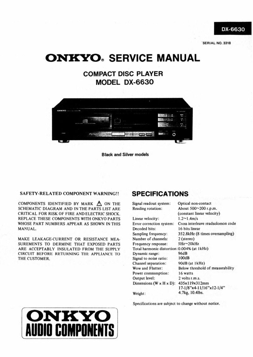
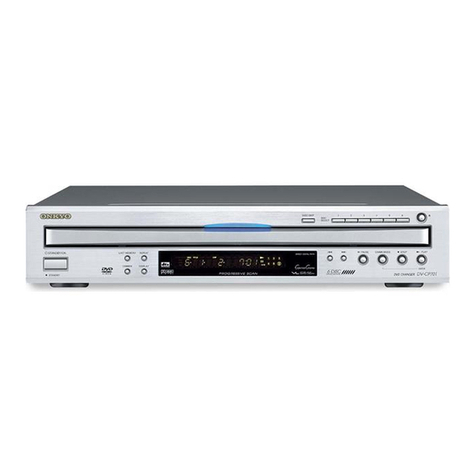
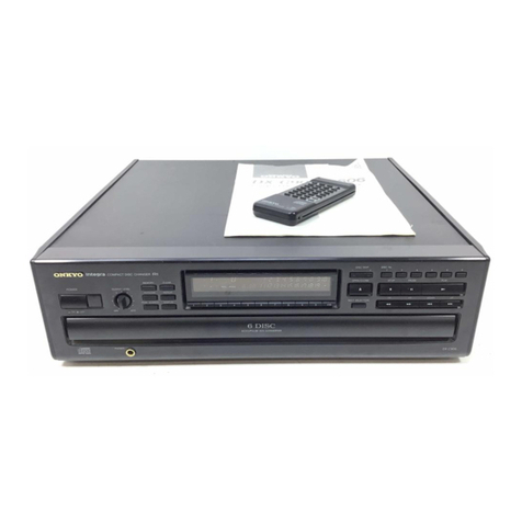
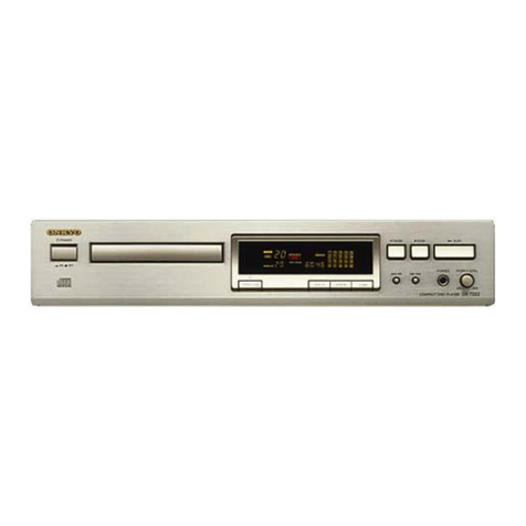
Onkyo DX-C106 User manual

DX-C208
~,
DX-CTO6E
REF.
NG,
3419
ONKYO
SERVICE
MANUAL
COMPACT
DISC
PLAYER
MODEL
DX-C106
MODEL
DX-C206
Black
model
BHUD,
BHUDN
120V
AC,
60Hz
|
BHUP
230V
AC,
S0Hz
|
BHUW
120/220
AG,
50/
60H:
|
|
BHUQA
240V
AC,
50Hz
BHUD.
BHUDN
|120V
AC,
60H2
|
SPECIFICATIONS
SAFETY-RELATED
COMPONENT
WARNING!!
C
a
pea
ea
i
.
%
;
Sianal
reacwal
system
Chatical
noracentaet
OMPONENTS
IDENTIFIED
BY
MARK
@
ON
Reading-rutation:
\bout
a0
—240e
pam
THE
SCHEMATIC
DIAGRAM
AND
IN
THE
PARTS
LIST
ARE
CRITICAL
FOR
RISK
OF
FIRE
AND
ELECTRIC
SHOCK.
REPLACE
THESE
COM
PONENTS
WITH
ONKYO
PARTS
WHOSE
PARTS
NUMBERS
APPEAR
AS
SHOWN
IN
THIS
MANUAL.
iconstrnt
lirear
veloerky|
Limear
werlocth
ay:
1.2
Lams
Ero
correcuion'svsteny
Cress
interleave
readsplamon
code
Deeded
brite:
1
BET
PMA
PLCS
LAA
COA
WER
TEA
MAKE
LEAKAGE-CURRENT
OR
RESISTANCE
Sapling:
Trequeney:
Sogk
2
(8
chimes
Uyersaanpling)
MEASUREMENTS
TO
DETERMINE
THAT
Number
of
channets:
“t
(Stereo)
EXPOSED
PARTS
ARE
ACCEPTABLY
IN
Freguency
Pesspiirie
JET
—OK
SULATED
FROM
THE
SUPPLY
CIRCUIT
BEFORE
Total
hannonte
distortion
0.4%
tat
thie)
RETURNING
THE
APPLIANCE
TO
THE
Livoainie
cine
4odR
iat
Tk}
CUSTOMER.
Signal
to
meise
ratin:
Shdistal
Liki
eg!
channel
separation
OMB
dat
bebe
Wow
and
Flatter:
Below
threshald
of
measurabilivy
Power
earsuniption:
LS
wats
Gutout
level
2
Volts
Tans:
Dimensionsd
Wy
x7
«= BS
|
2058
Aim
7
1a
dG
aay
eB.
Lobe
Lie’
Weieht
Tike.
1701s,
Specthicwhens
ate
subject
towheree
withaul
netic!
ONKYO.)
AUDIO
COMPONENTS

8)
Cer48/<)
9)
COanel<
TABLE
OF
CONTENTS
SERVICE
PROCEDURES
1.
Safety-check
out
SpecificationsS............
cece
cece
cece
ee
eens
1
After
correcting
the
original
service
problem,perform
Service
procedUres..........
0...
cece
eee
ee
eee
2
the
following
safety
check
before
releasing
the
set
Caution
on
replacement
of
optical
pickup......
2
to
the
customer:
Protection
of
eyes
from
laser
beam............
3
Connect
the
insulating-resistance
tester
between
the
Laser
warning
labels..........--.-
0.0
eee
eenee
3
IC
block
diagrams
and
descriptions............
4
plug
of
power
supply
cord
and
chassis.
Packing
Vie€W...
eee
ee
te
et
te
te
ee
g
Specifications:
More
than
10Mohm
at
500V.
Wechanism-exploded
view.
..........
0202
e
eee:
10
2.
Voltage
Selector
(Back
panel)
Changer
mechanics
ee
ee
ete
ee
ee
eee
eee
ee
10
Worldwide
models
are
equipped
with
a
voltage
selector
Pick-up
drive
unit.
...
0.0.0.2...
2...
ee
ee
ees
12
.
.
Chassis-exploded
view...
....
2c
ce
ee
ee
ee
ee
13
to
conform
with
local
power
supplies.Be
sure
to
set
Parts
list...
.
2...
cece
ee
ee
teenies
15
this
switch
to
match
the
voltage
of
the
power
supply
Block
diagram...
...
00.
cece
cee
eee
ees
17
in
user's
area
before
turning
the
power
switch
on.
Adjustment
procedures...
....
0...
eee
eee
eee
19
Voltage
is
changed
by
sliding
the
groove
in
the
switch
Printed
circuit
board
view
from
bottom
side..
21
Printed
circuit
board-parts
list.............
23
with
a
screw
driver
to
the
right
or
left.
Confirm
that
the
switch
has
been
moved
all
the
way
to
Disassembling
procedures...............0e00-,
29
;
;
the
right
or
left
before
turning
the
power
switch
on.
220V
~
120V
~
at
ACL20V
220V
~
120V
~
at
AC220V
CAUTION
ON
REPLACEMENT
OF
OPTICAL
PICKUP
The
laser
diode
in
the
optical
pickup
block
is
so
During
repair,carefulley
take
the
following
precautions.
sensitive
to
static
electricity
surge
current
and
etc,
that
the
components
are
liable
to
be
broken
down
or
its
reliability
remarkably
deteriorated.
(The
following
precautions
are
included
in
the
service
parts.)
PRECAUTIONS
1.Ground
for
the
work-desk.
Place
a
conductive
sheet
such
as
a
sheet
of
copper
(with
inpedance
lower
than
10M)
on
the
work-
desk
and
place
the
set
on
the
conductive
sheet
so
3.Grounding
for
the
human
body.
Be
sure
to
put
on
a
wnist-strap
for
grounding
whose
other
end
is
grounded.
Be
particularly
careful
when
the
workers
wear
that
the
chassis.
synthetic
fiber
clothes,
or
air
is
dry.
2.Grounding
for
the
test
equipment
and
tools.
4.Select
a
soldering
iron
that
permits
no
leakage
and
have
the
tip
of
the
iron
well-grounded.
5.Do
not
check
the
laser
diode
terminals
with
the
probe
of
a
circuit
tester
or
oscilloscope.
Test
equipments
and
toolings
should
be
grounded
in
order
that
their
ground
level
is
the
same
the
ground
of
the
power
source.
This
set
employs
a
laser.
Therefore,
be
sure
to
follow
carefully
the
instructions
below
when
servicing.
WARNING!!
WHEN
SERVICING,
DO
NOT
APPROACH
THE
LASER
EXIT
WITH
THE
EYE
TOO
CLOSELY.
IN
CASE
IT
IS
NECESSARY
TO
CONFIRM
LASER
BEAM
EMMISION,
BE
SURE
TO
OBSERVE
FROM
A
DISTANCE
OF
MORE
THAN
30cm
FROM
THE
SURFACE
OF
THE
OBJECTIVE
LENS
ON
THE
OPTICAL
PICK-UP
BLOCK.
LASER
WARNING
LABEL
The
label
shown
below
are
affixed.
1,
Warning
lable
This
label
is
located
on
the
arm
of
mechanism.
(D)
*
DANGER
_iNVISIBLE
LASER
RADIATION
WHEN
OPEN
AND
INTERLOCK
FAILED
OR
DEFEATED.
AVOID
DIRECT
EXPOSURE
TO
BEAM
UTION
—sazarvous
LASER
ANO
ELECTROMAGNETIC
RADIATION
WHEN
OPEN
ANO
INTERLOCK
DEFEATED
ENTION
—ravonnement
LASER
ET
ELECTROMAGNETIQUE
DANGEREUX
SI
ou
ver
T
AVEC
L
ECLENCHEMENT
DE
SECURITE
ADVARSEL:
USYMLIG
LASERSTRALING
VED
ABMING,
NAR
SIKKERHEDSAF-
BRYDER
ER
UDE
AF
FUNKTION.
UNDGA
UDGAETTELSE
FOR
STRALING.
(D)
VARO!
AVATTAESSA
JA
SUOJALUKITUS
OHITETTAESSA
OLET
ALTTIINA
NAKYMATTOMALLE
LASERSATEILYELE.
ALA
KATSO
SATEESEEN.
(A)
:
Danger
label
€
:
Except
120V
_
model
VARNING
©
:
Except
120V
OSYNLIG
LASERSTRALNING
MAR
DENNA
DEL
model
ineidnnineieiaiaiiaiaaiins
©,®:
Only
230v
model
—~3-
By
er4el<)
Dy)
Cenkels
PROTECTION
OF
EYES
FROM
LASER
BEAM
DURING
SERVICING
Laser
Diode
Properties
2.
Material:
GaAS/GaAlAs
Wavelength:
780nm
Emission
Duration:
continuous
Laser
output:
max.
0.5mW*
*This
output
is
the
value
measured
at
a
distance
about
1.8mm
from
the
objective
lens
surface
on
the
Optical
Pick-up
Block.
Certification
label
(120V
model)
This
label
is
located
on
the
back
panel.
PRODUCT
IS
CERTIFIED
BY
THE
MANUFACTURER
TO
COMPLY
WITH
DHHS
RULES
21
CFR
SUBCHAPTER
J
APPLICABLE
AT
THE
DATE
OF
MANUFACTURE.
MANUFACTURED
3.
Class
1
label
(Except
120V
model)
This
label
is
located
on
the
back
panel.
LUOKAN
1
LASERLAITE
“CLASS
1
LASER
PRODUCT”
KLASS
1
ADVARSEL
Denna
maekning
er
anbragt
pa
apparatets
hojre
side
og
indikerer,
at
apparatet
arbejder
med
laserstraler
af
klasse
1,
hvilket
betyder,
at
der
anvendes
laserstraler
af
svageste
klasse,
og
at
man
ikke
p4
apparatets
yderside
kan
blive
udsat
for
utilladelig
kraftig
straling.
APPARATET
B@/R
KUN
ABNES
AF
FAGFOLK
MED
SE
RLIGT
KENDSKAB
TIL
APPARATER
MED
LASERSTRALER!
Indvendigt
|
apparatet
er
anbragt
den
her
gengivne
advarselsmérkning,
som
advarer
imod
at
foretage
sadnne
indgreb
i
apparatet,
at
man
kan
komme
til
at
udsaette
sig
for
laserstraling.
VAROITUS!
LAITTEEN
KAYTTAMINEN
MUULLA
KUIN
TASSA
KAYTTOOHJEESSA
MAINTULLA
TAVALLA
SAATTAA
ALTISTAA
KAYTTAJAN
TURVALLISUUSLUOKAN
1
YLITTAVALLE
NAKYMATTOMALLE
LASERSATEILYLLE.
LASER
APPARAT

PACKING
VIEW
PARTS
LIST
REF.NO.
PART
NO.
201
800306
202
27270357
203
24822012
204
27265155A
205
834430088
206
29052400
29052401
207
29091562A
208
2909
1563A
209
29100038A
210
29110071
211
282301
212
29095019-1
214
29095654
216
29361434
217
29361433
0)
eraele
be)
Ceakel-)
DESCRIPTION
M5
X20,Wing
screw
15
X5
X0.5,Spacer
Bracket,pin
Ring,cover
3TTS+8B(BC),Self-tapping
screw
Master
carton
box
<DX-C106>
Master
carton
box
<DX-C206>
Pad
L
Pad
R
Styrene
bag
Dampion
tape
Sealing
hook
0.5
X
600
X<
800,Protection
sheet
Protection
sheet
Label
Label
PART
NO.
DESCRIPTION
Accessary
bag
ass'y
2010098A
Connection
cord
2010200
Remote
control
cord
24140227
RC-227C,Remote
control
unit
<DX-C206>
3010054
UM-3,Two
batteries
<DX-C206>
29341725
Instruction
manual
<D>
29341726
Instruction
manual
<P/W/Q/C>
29365019A
Warranty
card
<N>
29358002)
Service
station
list
<N>
25055040
CV-K-2,Conversion
plug
<W>
29100097
350
X
250,Styrene
bag
NOTE:
<D>:120V
model
only
<P>:230V
model
only
<W>:
Worldwide
model
only
<Q>:240V
model
only
<N>:U.S.A.
model
only
<C>:Canadian
model
only
ok
DX-C206(BH)UWX-D
type
is
the
same
as
the
DX-C206(BH)UW
with
the
exception
of
the
foliowing
sections.
9
|
22053400
|
2805240
3
Waren
ead
————=*|
29365001
[3
[
[sevice
sadontise
|
29358002
(BH)UWX-D
(BH)UW
CAUTION:
How
to
lock
the
transport
screw
(
when
the
tray
opens
)
1.Press
the
memory
button.
2.Press
the
close
button
to
close
the
tray.
3.Turn
the
power
switch
off
after
more
than
3
seconds.

hs
@)
oO
©
=
a
>
2
ao
QO
&
Os
i
<<
o
=
i
©
=
=
XY)
o
em
tL
ZO
$
2
&
=
uw
°
=
Ow
eRe)
Qe
OQ
«x
><
aya)
~10—

DX-C206
DX-C106
PARTS
LIST
CMC-B
BU-5BD3
REF.NO.
PART
NO.
DESCRIPTION
REF.
NO.
PART
NO.
DESCRIPTION
l
24802004
Chassis
ass'y
351
838426088
2.6TTB+8B(BC),Self-tapping
screw
2
24810007
Gear
A
352
24818001
Insulator
A
3
24810008
Gear
B
353
24828001
Sled
shaft
4
248
10009
Gear
C
354
82142003
2P+3F(BC),Pan
head
screw
5
24810010
Gear
D
355
248
10004
Wheel
6
24834003
Washer
356
248
10005
Wheel
7
24840019
E
ring
921__24505321_AR-AS-LRF/Servo
pc
board
ass'y
-
8
248
16003
Belt
923
2043120010
Flexible
cable
9
248
16004
Belt
924
24110011
KSS-240A,Optical
pickup
10
34816005
Belt
M101
24804002
Sled
motor
ass'y
11
24810011
Gear
cam
A
M102
24804003
Spindle
motor
ass'y
12
24810012
Gear
cam
B
$101
25065446
NLF-11022,Leaf
switch
13
801502
Self-tapping
screw
14
24840020
E
ring
15
24804005
Motor
ass'y
16
801503
Pan
head
screw
17
24822006
Plate
holder
18
24828004
Shaft
19
24840021
E
ring
20
24820004
Spring
21
801504
Pan
head
screw
22
248
14002
Am
switch
23
24822007
Plate
switch
24
801505
Screw
25
24822008
Plate
B
26
801506
Screw
27
24822009
Plate
28
801507
Screw
29
801508
Screw
30
24840009
Connector
pc
board
ass'y
25065375
NMS-1219,Switch
CN101
24840022
Connector
CN102
24840012
Connector
CN103
24840011
Connector
31
801506
Screw
32
801509
Screw
33
24840013
Wire
34
24802005
Sub
chassis
35
24840014
Lift
lever
36
801505
Screw
37
24506980
BU-S5BD3,Pickup
drive
unit
38
801510
Screw
39
24840015
Bush
40
24820005
Spring
41
24820006
Spring
42
24820007.
Spring
43
24820008
Spring
44
24840016
Flexible
wire
45
24840017
Vinyl
sheet
46
24840018
Nylon
rivert
—~11-—-

eo)
Ser4e)-
co
o'
9
><
fa
PICK-UP
DRIVE
UNIT(BU-5BD3)
gy
uw)
)
355
M102
(Including
the
chassis
@
A)
.
we
—~12—

\
on
AN
Wks
-
A
Yaa
9019°XxG
“Eel
M3IA
G4A001dXa

Q701
9-BT—1
09GK
123
4
5S
&
7
@
9
1041
12323
14.18
16
17
1819
20 21 22 25
2
2S
26 27
20 29
WO
Bl
2
ES
Bt WS
BE
57
3B
39
40
41
42
SE
CCELECC
EMME
EECEEEE
mC
CCCECOC
NAD
1S~4478
|
Se
cin
|
Lisi
ecmeceaee!
f
!
BERRRARRARRBARAARRABARaARaDAD
aaa
aed
emgt
Rae
—-—
-
—--
—
PTT
ES
GS
SRS
ES
ES
SS
AS
OS
LS
SS
NN
SS
AS
PS
AS
SS
oP
eO000000
e
O00
®
OOOG0%9
O°
00000
Odg
'
ECECCeccee
;
een
~
wees
=
a
aD
]
R817
rei7~
|
PREIS
REZ
nee
47K
|
P41
=
be
owe
a
@202
ie
=|
a
+5V
mo
ie
CXP50116-383Q
wwe}
__
babe
P|
XTAL
O
anes
2
RO.§
ADO
sorver
—
APES
RO-PS
ore
2
ee
=
AD2
he
pews
="
Z
>
ow
(—aal
ork
dds
2S
aan
as
an
i
a
ROT.HI
LD.HI
RMCN
2
NRSC
aMUT
ji
R
DFT.SW
SENS
OxX-~<c206
rats,
«7k
-
DATA
a=
'
SQSO
FOK
ae
ee
[a
ama:
a
I
a
|
|
|
-
ev)
GETREEEEEES
GED
GUEEEEEEEIEEEES
GEES
CD
CES
on
cee:
SRE
Ge
ED
CE)
EEEEY
CF)
ERED
GR)
GESTEETEEED
Ge)
Gees
oe
ee
oe
ee
om
eee
ow
CES
Ob
Gees
On
Gee,
©)
ee
ow
ees
g
pf
|
rT
~px-o206
|
3
RS
ES
|
pieeweroes.
|
@
art
Po20y
2210
Kk
&
om
Sere
cee
4
RN2207
1SS270A
N
[D203
MTZ5.
68
C437
C4359
220/16
220/16
i
pane
aan
rT
z20AM
2.7
C427
|
1.
1k
R423
bd
tuba
R435
ined
300
C4135
58
222
CS
9401
(202
ae
RRALEO
c4ags
‘wit
P|
R
Loh
(©)
41
we
Tye
va
@402
(2/2)
722
-
“N445600
|
40663
ic
11
INOUT
[NOTE]
@
THE
COMPONENTS
IDENTIFIED
BY
MARK
AN
ARE
CRITICAL
FOR
SAFETY.
i
REPLACE
ONLY
WITH
PART
NUMBER
SPECIFIED.
;
®
VOLTAGE
(MEASURED
WITH
VOLTMETER)GCIIS
DC
VOLTAGE.
2
OUT/AN
@
ALL
PNP
TRANSISTORS
ARE
EQUIVALENT
TO
2SA1015-GR
UNLESS
t
OTHERWISE
NOTED.
OUTAN
@
ALL
ee
ren
ARE
EQUIVALENT
TO
2SC1615-GR
UNLESS
'
OTHE
.
‘
@
ALL
DIODES.
ARE
EQUIVALENT
TO
185133
UNLESS
OTHERWISE
NOTED.
‘
4INOUT
@
ELECTROLYTIC
CAPACITORS
(-¢)
ARE
IN
sFAW.
;
@
ALL
CAPACITORS
ARE
IN
pF/SOW
UNLESS
OTHERWISE
NOTED.
\
EXBpF-030,
33pF+3350.
3350p
F331,
0,
O33
4F-+3335
CONTROL
#@ALL
RESIS
ARE
[
174
WA
UNLESS
OTHERWISE
NOTED.
?
®
THE
THICK
LINES
[N
PC
BCARD
ARE
THE
PRINTING
SIDE
OF
THE
PARTS.
‘
’
t
§
CONTROL
Ex
le
PRINTING
SIDE
er
ec!
1S
SUBJECT
TO
CHANGE
FOR
IMPROVEMENT.
|
i]
iL
I
7Vss
—
'

Q701
3-B8T—1
09GK
423
4
5S
6
7
8
9
10114
1213
14 16
16
17 16
19
20 23
22
paw
LEDC
DDE
EEE
ame
oremmeees
ax
come
NAD
1S-4478
ee
See
ee
DX-C206
ONLY
{LE
Ey
el
EEREREREEE
10
999990
0
O18
¢
SCCECECCCEE
mi<efa
wieic
rog
aaa
HOU
()
O
)
oe
5
>
OULU
|
Za
pt
tT
TT
et
i
wo
Or
NM*tN
aa
rerreresr
&anaaaad
Vv
Q202
CXP5011!
ie
LE
bo
Ke
He
6 8
1s
|4
Aracate
Bod
did
06
(22)
“
MUTE
|
Fh
sack
|
z
O
$@so
'
th)
AAA
ae
la
Ie
fe
Pease
eeae
bagsgbee
mys
Be
|
li
ie
ee
ees
eee
a
th
eet
he,
a
i
a
Ses
TC93237BN
1912
0913
4
1SS270Ax2
li
1
823404
ost
taek
@305
DPT
He
[5.9j
R436
mat
(S
anc
1
Or
o
e
TELS
02
(2/2)
an
t
Rs
JM4560D0
428
R4:
R'
a
iS
R424
HM
47/60
23
¢
D915
206
j
ss
ome
te
C3
Jepee0
cc
oS
[os
@
THE
COMPONENTS
IDENTIFIEDBY
MARK
A\
ARE
CRIT
REPLACE
ONLY
WITH
PART
NUMBER
SPECIFIED.
@
VOLTAGE
(MEASURED
WITH
VOLTMETER)GIS
DC
VOL
@
ALL
PNP
TRANSISTORS
ARE
EQUIVALENT
TO
2SA10
OTHERWISE
NOTED.
@ALL
NPN
TRANSISTORS
ARE
EQUIVALENT
TO
2SC1E
OTHERWISE
NOTED.
@ALL
DIOOBS
ARE
EQUIVALENT
TO
185133
UNLESS
@
ELECTROLYTIC
CAPACITORS
(-#)
ARE
IN
sF/AW.
@
ALL
CAPACITORS
ARE
IN
pF/S0WV
UNLESS
OTHERW:
EXSpF-030,
33pF-3350,
S30pF+3351.
0,
eee
Lape
et
@
ALL
RESISTORS
ARE
IN
OHMS
1/4
WA
UNLESS
|
@
THE
THICK
LINES
IN
PC
BCARD
ARE
THE
PRINTIN
EX
w
PRINTING
SIDE
ci
1S
SUBJECT
TO
CHANGE
FOR
IMPROVEMEN

cenit
Vv)
—"
:
:
We
ie
OO
oe
EE
§
;
aERBCACCRRC
RE
AONEERREEEEFEEE
TL]
3
a
De)
.
ew
-
eaiaiTaAi/AATAATIAA
TAAL
_
SS
|
ae
|
se
35
etal
oe
|
905~0808
1$R139~-100
fi
D906
ag
1
ps0e
D
1
17]
i
rte
HLL
La
ba
a
Mr
Bi
|
se
MEF
[per
A
barre
Lo|
#5
Loa
lo
LAS
le
tot
|
|
of
az
bai
|
=
{e
[we
==
a
|
|
|
i
SS
a
a
yh
[|
|
=
h
met
|
a)
|
|
|
HE
al
i
|
o
:
<
|
;
a“
t+
°
Sy
;
|
(8
|
:
a
LO
O
|
z
ee
bel
cs
L—,
3
eee
Ge!
i
a
a
—
: :
:
<3
|
1
e
<i
—
mee)
ti
(a
Fed
e]
IS}
og
|
3}
ro
eel
e
©.
%
Lees
3}
P&E
el
ge
ol
afe
aie
$e
r
Hs
mage
3
2
33
z
gis
:
4
Q
sy
@¢

mains
sutddei-Aes(Md9+d
LLE
LO
4sRIg
uoTysn>
maros
Buiddei-Jjog‘(a)ad8+
ALLE
Teas
JaA07
uoTYsnz)
LE
eye
wiy
Avr‘uorysn>
q
PyoLg
¥
pyApeIg
mars
Suiddei-yjag
(Og)
qk+SLLE
mais
3uiddel-7]25
(Od)
dOl+MLLE
moses
Suiddel-319$'(9Wd8+d
LLE
mars
Surddei-y[29(D
4)
9+
@LLE
HD
S404
Ho
aude
Ho
dep
wa
aieid
opis
wy
aed
apis
J
aed
apis
jesnole)
eqn],
tun
sap
drop‘
eq
gs-Nd
WsTuEyoow
JasueYyD
g-OWD
Ia[oy
Ja[[OrIFeYS
ABiy
qeas‘1yeus
IvoL)
ory
U
[fer
apn
"J
[les
opinH
NOLLdIdosaa
OODOEPEES
TLOZTBPT
LOOSERPT
S8O0EPIES
SOO0PEHZ
LSPOPT
8?
OLOTTS
PT
LOOPL8PZ
S009E8
FC
LOOTCRPC
TOOCTRPT
8800EPFES
OOTOEPFICS
OSO0EFBES
B9DOLPSES
GSLVIOELT
V61OI
8137
PLYLOELZ
ON8L9TLZ
B9LLOTLT
VLOLLOTLT
VO9PTOELT
LOOPES
KT
086906
F7
PILR69)S
HZ
VS9PTOELT
BOEO9TLT
OTOPIOELT
G0LO9TLE
OLPTOELZ
VOLPIOELZ
ELPIOELT
VCLPIOELT
‘ON
Lavd
SEI
Lel
o€l
Sel
Pel
cel
cel
Lel
Scr
tZl
cet
{él
0cl
611
SIT
Lil
9IT
Sit
Pit
eli
cll
IIl
Olt
601
801
Lot
901
sol
pO!
col
cOl
tl
‘ON
Had
(9029/90L9-X0
1SGONW)
wsTueysow
Jasueys
GD‘D-SZS-GON
Asse
preoq
od
Josues
ISI‘
1-1
8h>-MSWN
Asse
preog
od
wna
A[ddns
samod‘!-08¢p-Sd¥N
Asse
preog
of
sas
JaM0d'1-6L7>-MSVN
Asse
preog
od
yinono
Aepdsiq'
1-82
¢>-SI
WN
Asse
preoq
od
inom
ure
1
-LLbp-
adv
WN
JOWJOJSUCN
JOMOd'CZPIE-.LUN
pisos
Aiddns
lamog
‘S149-ON-SV
209‘91-8-9L-
UL
rosuep
Toqr'y
21929
IELT‘O10P67-
LDADN
sodwe[D‘NOI-3IN
Jopulg
NOLLdIedOsad
<q
<j
1-18S661H!
1-08S661HI
1-6LS661HI
T-82S661HI
T-LLS661THI
68L00ET
OPTEST
JO
BOL
EST
LOGOLZ
LO809£67
OLOP6TI
POT
122097
802097
‘ON
Lavd
mais
Sutddei-s19¢(Og)dZ1
+d
LLP
mois
Suiddel-j195
(OD)
A8tS.LLE
M198
Sunddet-j19$(OM/d8+d
LLE
[oued
Avs,
apiny
Jomod
‘qouyy
3ura‘(SNS)E-SD
y
deo
pug
|
des
puq
ospeg
[aued
jo1y
wOIysny's
x
O81
XO
Jaa00
doy
Joys?
AA
‘NAOT
ENAA
masos
Surddet-Fag‘(OMSTZ
+d
LLE
MAIS
peay
UEd
(DYNAI+dE
maios
Suiddei-qeg‘(DMOst+D.LLy
moios
Suiddel-j199‘qg+M
LLE
mains
suiddei-jjeg
(Dg)
A8+S.LLE
mois
Surdder-ya¢'(DMdR+d
LE
moins
sunddel-j799
‘(OM
ast+
HLL
Z
WOTYSN'OZ
X
OF
X
€
IZ
J9PIOH'S91-SdOW
sn
pios‘durysng
rn
uorysn,)
en
a2]
en
JapIOH'
DEO
A
mn
JoploH
TO6L
Jap|OH
IOP[OH
106d
Dd
19998
g
1067
jourd
yoeg
76
SISSEUD
66
Avid‘qouy
6
ated
wvaja
16
yeydRIQ
1U014
‘ON
Ada
NOLLATYOS3ad
V
OZIOPPELS
8800EPPES
OSO0EPEES
PIPLIZLZ
ASLLLOTLT
OPT
ZEST
TOLOL68
AGVCSZIBT
ASVTSTIBT
GOTSET8C
EIPIITLZ
O890F
187
10666THT
OTOETTOB
LTIOEPEEB
S00EFITS
68007
P08
S800E
TEES
S800EFPCS
O800EFECS
S8O9CPRES
LOITYT
87
TOGO6TLT
OSLOOLLZ
GOOSES
PC
VSZSLILT
T8B06T
LT
69806117 PLBO6IL7
66806117
P890E
TLZ
V2LSICILZ
LSTOOTLE
ESSPCEST
PCEOT6I8Z
PO9OTILZ
‘ON
LavVd
‘ON'ATa
90L0°X0
1S0G0OW
LS!
SLYVd
—
15
—

co
re)
ql
9
«
Oo
DX-C106
‘CaeldIDadS
WHEWNN
LYVd
HLIM
AINO
AOV
Idd
MOOHS
OILOATA
GNV
FYI
AO
ASTY
YOs
TVOLLIYO
avy
WUVWAW
Ad
GSMELNAGI
SLNANOdWOD
SHL
“ALON
Apdo
}2poul
AOPZ:<O>
AyTuo
J2poul
apimppyloAy:<M>
ATMO
JopOul
ANET:?<d>
Ajuo
[9pou
AQZI:<d>
‘ALON
wistuvysow
Jagueys
‘D-SZS-dON
Asse
preog
od
Josuas
3s1(]'Z-18h>-M
SVN
<O/d>
Asse
pseog
od
mano
Ajddns
1amod'gZ-08tt-SdVN
<M>
Asse
pseog
od
s1no119
Atddns
samog'yZ-08b>
SdVN
<>
Asse
preog
od
nono
Ayddns
12M04'7-08ht-
SAWN
Asse
preog
od
yous
10M04‘7-6Lb>-
MSWN
Asse
psvog
od
wnaito
Aetdsiq‘7-8L¢>-
SIG
VN
Asse
preg
od
119
UIE
'Z-LLPP-AV
WN
<)>
JouOsueN
9MK0g
OZ
I-LIN
<A>
JOULOJSUeT
IMO‘
ONdZPII-.LdN
<q>
Jounossuen
JomOd'dZpl
I-LdN
<(]>
JouIojsuen
19M0g'
Zbl
-LdN
<M>
YSUMS
10199198
BdRI[NA
‘d8SZI-SSN
<Q>
pios
Aiddns
mMmog
‘V¥S-SV
<A/d>
pioo
Ajddns
lamog‘qgq0-SV
<q>
pioo
Aiddns
samog
‘SE#S-OITSV
2109'91-8-91-UL
<O/M/d>
Jo8uep'poqe]
31929
TE
LJ
01067"
[DHON
s9die|D‘NOT-3IN
JOpULY
<M>
L
19998Ig
<O/M/d>
1
Sse9‘Teqe'T
NOLLdMdOSad
dq
dd
<dd<d<d<
c
18SZ0THI
ac-O8Sc0cHI
W7C-08SZ0ZHI
c-08Sc0ZHI
c-6LSZ07HI
Z-8LSCOCHI
t-LLSZOCHT
C6LOOET
16L00€7
O6L00ET
68L00E7
CZTIS9OST
OLIESC
JO
SITEST
6PLEST
ObTEST
JO
R9OTEST
LOGOLZ
LO8O9L6z
OLOP6ZI
HOT
E097
807097
STSIPELZ
L8909£67
‘ON
LUVd
IZ
sn
mn
en
wn
in
LO6.L
7068
106d
1067
v6
€6
26
16
OL
GL
‘ON
dda
<d>
NIA/WAS
Pqe'T
<d>
WHS
[qe]
<d>
[?4eT
<O/M/d>
JoselfeqeT
mains
duiddel-jpas‘(OgdZI+d
LL?
ois
Suiddes-j799
(Iq)
as+S.LLE
mais
Suiddet-jpog(OMdst+d
LLE
joued
Avery,
apmy
Jomod‘qouy
gury‘(SNS)e-SD
y
deo
pug
"J
deo
pug
aspeq
joued
qwo1y
UONysSN}'g
x
O8T
X
$0
J9A09
dol,
JOYSPAA
NAOT
&
ENA
moss
Suiddet-j12$(OG)STZI+d
LLE
M2IDS
peoy
Ued(OG)NIAG+dE
maios
Surddei-3199'(O@)O8t+O.LLy
moins
Buiddel-jp9s‘ESt+M
LLC
Mains
Suidder-jjag‘(Dgq)as+S.LLE
mois
Suiddel-Fos‘(dqQd8+d
LLE
mais
suidde-79¢'(Dq)
ast
GLLI'Z
uorysay
‘NZ
x
O£
&
€
JIPjOH'S91-SdOW
ploo‘suTysng
uoTysn)
37]
<O/d/d>
POH
DEOMI
Japjoy
JaploH
JaploH
Od
Ae
<(>
joued
seg
<AA>
[ued
yorgq
<q>
[aued
soeg
<q>
joued
yoeg
SISSEYD
kejd‘qowy
areld
weap
JayoeIQ
Woy
NOLIdMDsagd
VEPELOLE?
V86TI9L67
VIT809£62
BITI9L6Z
OTIOFPEES
BRO0EFPES
O800EPEES
vVIPTITLE
ASLLLOTLT
OVIPCEST
LOLOTE8
AGPTSTIBT
AB8PTSTI
BE
661SE187
SIPLItLZ
O890PE8Z
106661HI
OTOETTSB
LTIOEPEES
QOOEPITS
6800PP0ES
B800ET
LES
B800EPPKES
O800EPEES
S809TPEES
L6LEVT8Z
CO606TLT
OSLOOELT
BOOIES
HC
PSZSLILE
TR8061
LZ
698061
L7
PL806I
LT
66806117
P890CT
LT
BPITZILZ
WSLSITILZ
VPLSITILZ
VELSTZILT
LSZOOTLT
CBSPCEBT
VSC916T8Z
P69OTTLE
‘ON
Lavd
PL
tL
tL
ld
£9
co
19
6S
8S
LS
$&
$S
€s
(AS
Ig
ce
Te
62
LZ
SZ
ec
ce
1¢
02
él
Lt
91
v1
tl
al
a
Ol
Nn
mH
mM
I
‘ON
Ada
9029°X0
1300W
-—-16—

ATWO
90ZD-XC1_
[OPOW
a
|
a
>
z
w
p.
se)
a]
=
m
a
We
SCIMd
THOM
¥YOL03
13S
ASVLIOA
2006S
YSWHOISNVYL
MS
3.LNW
800
g3axl4
©
aaxis
G
C
)
MS
ALNW
ZOD
YOLV
INOS
-Gi-
—LL-
oe
5
9019-xd
:
GNO
BLOWS
|
°
INO7
NI
1a
1
:
O
-
Jasnoy
yo
apes
Cw)
5
(we?
I
2
<<
(W)2
(We
z
3AIwa
MS
Jani
4
YOLOW
1020
|
|nouvaado|
=B
5
|
O1z0
GOZO
€0Z0
NM
oO
w
>
.
oO
a
3
9060
3B
mo
4
o
/\8
efzi5
&
9
|x
20
=
2
©)
:
Se
t2
Ta
CO
lnwH
oO
2D
oO
4
=
ob.
He
3
6
16
5
O
rm
C
“4
,
z
|afx
ie
zim
12
lz
r
x
HOLY
1ND3ay
4
Ol_
iN
ao
©
lo
b
o
la
=
1060
AG+
cjz
YG
IF
14
lo
bf
&
wo
Dn
1A
YOLVINOSY
|
£060
Ad
+
YOSS390¥d
OYDIW
v9
yYOLVINDAY
£9
iH
‘G71
vO6O
Ag+
.
;
Ley
2
Bie
is
a
gee
salsiaeets
|e
ie
yYOLV
1NOsHY
x
c
le
S060
Ag
—
.
9s0]
|3
Z)xi%
CWI
1S1S
|
on
it
4
ZzHWS%]
[A
5
R
|
Aa|A
1G
|
0
|
o
”
@)
=
a
3
YOSN3S
v
3LOWSY
OLN
130
NOILISOd
x
NOILISOd
dols
Tasnoyyo
asnouv
ZOO0
Kekels)
LINOMID
.
3LVv9
60Z0'80zZD
oSO0
IVL.x
ZOzZx
MS
3LNW
4¥3453n¢a
90FD
¥3aL
lis
SAILOV
P4ig¢
430178
Ford
cOpd
“d
WV
V/G
ova!
YOLVY
VdWOD
W43
pH
H3L4
SANOD
OAuaS
Q37S
TVILNaY
ASIC
ya)x
ya4ang
ONIMDVYL/SNIOS
aa:
e
lo1ot
|Or
aa
MS
FOrd
>
3Lnw
SOO
lol
WVYSVId
HOO
TE
9019°X0
9019°Xd
Or)
-VYO
ola
-¥
CI

ADJUSTMENT
PROCEDURES
It
is
not
necessary
to
perform
the
adjustment
of
optical
pickup.
REFERENCE
This
confirmation
should
be
made
when
replacing
the
optical
pickup.
Focus/Tracking
Gain
Adjustment
1).
Connect
the
oscilloscope
to
test
points
RF
and
VC.
Af
;
,
|
ay
Osilloscope
requency
response analyzer
158
necessary
in
DC
range
order
to
perform
this
adjustment
exactly.
However,
this
gain
has
a
margin,
so
even
if
it
ts
slightly
off,
there
is
no
problem.
Therefore,
do
not
perform
this
adjustment.
Focus/tracking
gain
determines
the
pick-up
follow-
Mechanism
pcb
up
(vertical
and
horizontal)
relative
to
mechanical
TP(RF)
C3
C)
noise
aid
mechanical
shock
when
the
2-axis
device
TP(VC)
G
CO)
operate.
However,
as
these
reciprocate,
the
adjustment
is
at
2).
Turn
the
power
switch
on.
.
the
point
where
both
are
satisfied.
3).
Load
the
test
disc
YEDS-18
on
the
tray
and
press
the
play
button.
—_
. |
|
4).
Confirm
that
the
waveform
on
the
oscilloscope
is
optimum
eye
@
When
gain
is
raised,
the
noise
when
the
2-axis
;
device
operates
increases.
pattern
and
optimum
level
as
shown
photo
1.
@
When
gain
is
lowered,
it
is
more
susceptible
to
Optimum
eye
pattern
means
that
shape
"<>"
can
be
clearly
a
mechanical
shock
and
skipping
occurs
more
easily.
distinguished
at
the
center
of
the
waveform.
@
When
gain
adjustment
is
off,
the
symptoms
below
appear.
CHi
86
49445
.
SIH
;
F
bee
.
asin
sad
segete
@
The
time
until
music
starts
‘oN
-
becomes
longer
for
STOP
(yx
I
b
—>
DPLAY
or
automatic
KK
CXF
selection
(Hed.
PPA
buttons
low
or
high
KAAAN
ice
yd
AS,
YOK
pressed.
(Normally
takes
epee
*.¢.8
about
2
seconds.)
e
Music
does
not
start
and
disc
continues
to
rotate
for
STOP
>PPLAY
or
automatic
selection
(
Hed
bP
i
buttons
pressed.)
e
Disc
table
opens
shortly
low
or
high
_
after
STOP
>DPLAY.
e
Sound
is
interrupted
dur-
ing
PLAY.
Or
time
count-
er
display
stops
progress-
ing.
e
More
poise
during
2-axis
device
operation.
—19—

DX-C206
DX-C106
The
following
is
a
simple
adjustment
method.
5.
Connect
oscilloscope
to
RF/
Servo
board
TP
(TE).
6.
Adjust
RV101
so
that
the
waveform
is
as
shown
in
~
Simple
Adjustment
—
the
figure
below.
(tracking
gain
adjustment)
Note:
Since
exact
adjustment
cannot
be
performed,
remem-
ber
the
positions
of
the
controls
before
performing
the
adjustment.
If
the
positions
after
the
simple
adjust-
ment
are
only
a
little
different,
return
the
controls
to
the
original
position.
VOLT/DIV:
1V
TIME/DIV:
2mS
—
dv
oscilloscope
(DC
range)
Procedure:
main
board
a
TP
(FEO)
Q<-——zy——_—©
+
i
@
Incorrect
Examples
(fundamental
wave
appears)
fe
TP
(TEO)
Ow-
~7
low
tracking
gain
1.
Keep
the
set
horizontal.
If
the
set
is
not
horizontal,
this
adjustment
cannot
be
performed
due
to
the
gravity
against
the
2
axis
device.
Insert
disc
(YEDS-18)
and
press
PD
PLAY
button.
Connect
oscilloscope
to
RF/
Servo
board
TP
(FE).
VOLT/DIV:
TV
TIME/DIV:
2mS
—ov
tw
Adjust
RV102
so
that
the
waveform
is
as
shown
high
tracking
gain
(higher
fundamental
wave
than
for
low
gain)
in
the
figure
below.
(focus
gain
adjustment)
-
&
VOLT/DIV:
IV
TIME/DIV:
2mS
VOLT/DIV:
100
mV
TIME/OIV:
2mS
W—s00mvy
OV
@
[ncorrent
Examples
(DC
level)
changes
more
than
cn
adjusted
waveform)
.
Adjustment
Location:
RF/
Servo
board
low
focus
gain
VOLT/DIV:
100
mV
TIME/OIV:
2mS
[Victos
—
250mV
-
O0
RVIO2
FE
FO
GAIN
ov
On
high
focus
gain
VOLT/DIV.
100
vio
TIME/DIV)
2mS

PRINTED
CIRCUIT
BOARD
-—-
PARTS
LIST
MAIN
CIRCUIT
PC
BOARD(NAAR-4477-1/2)
CIRCUIT
NO.
Q201
Q202
Q203
Q205
Q206
Q207
Q400
Q401-Q404
Q901
Q904
Q905
Q208
Q209
Q210
Q405-Q408
Q903
Q906
D201,D202
D203
D901-D908
D909
D910
D911
D912-D914
D915
X201
X202
C202
€203,C209
C205
C206
C207
C213,C218
C214-C216
C219
C221
PART
NO.
ICs
22240487
22240591A
222840661TOS
22240239
22240034
22240018
22240535
222579
22278005SMIT
222780085
MIT
222790085
MIT
Transistors
2213570
2211454
or
2211455
2213590
2211705
or
2211706
2201074
or
2201073
2211504
or
2211503
Diodes
223205
224450562
22380032
223205
224452202
224450512
223205
224450753
Ceramic
oscillator
3010188
X'tal
3010159
Capacitors
374724734
354721019
374721034
354781099
354762209
374721044
354744709
354744709
354780479
DESCRIPTION
CIRCUIT
NO.
CXD2500AQ
C222
CXP50116-383Q
C223
4066B
C226
TA7291S
C230
LA6510
C231
M51943ASL
€403,C404
TC9237BN
C413-C416
NJM4560D
C419,C420
M5F78M05
C427,C428
M5F78M08L
C429,C430
M5F79M08L
C431,C432
C437-C444
RN1207
C905,C906
28A1015-Y
or
C909,C910
258A
1015-GR
C911
RN2207
C912,C913
2SD655-E
or
C914
2SD655-F
C915
2SD880-Y
or
C916
2SD880-O
C917
2SA950-Y
or
C918,C921
2SA950-O
R216
1SS270A
MTZ5.6B
P101
1S$R139-100
1SS270A
MTZ22B
P401
MTZ5.1B
P102
18S270A
MTZ7.5C
CTS4.50MGW040
AT-38-169
0.047
n
F£5%,50V,Plastic
100
«
F,6.3V,Elect.
0.01
«6
F45%,50V,Plastic
0.1
x
F,50V,Elect.
22
4
F,35V,Elect.
0.1
4
F£5%,50V,Plastic
47
«
F,16V,Elect.
47
»
F,16V,Elect.
4.7
2
F,S0V,Elect.
—
23
—
PART
NO.
Capacitors
354724719
354782299
354724719
354721019
354744709
374724744
374722224
374721824
393184707
374722734
374722224
393142217
354742229
393142217
354784709
354764709
354742229
354741029
354744709
354780229
393144707
Resistor
49163472408
Socket
25050512
or
25050861
Terminals
25045361
25045362
Radiator
27160176
Pan
head
screw
82143006
Holder
27190751
Bracket
27141059
Cord
ass'y
2065525
100
2065525080
D)
Ceraelc
DX-C106
DESCRIPTION
470
»
F,6.3V,Elect.
0.22
4
F,50V,Elect.
470
1
F,6.3V,Elect.
100
«
F,6.3V,Elect.
47
«
F,16V,Elect.
0.47
p
F£5%,50V,Plastic
2200pF
+
5%,50V,Plastic
1800pF
+5%,S0V,Plastic
47
«
F,SOV,Elect.
0.027
«
F£5%,S0V,Plastic
2200pF
+
5%,50V,Plastic
220
«
F,16V,Elect.
2200
«
F,16V,Elect.
220
«
F,16V,Elect.
47
4»
F,S0V,Elect.
47
»
F,35V,Elect.
2200
«
F,16V,Elect.
1000
»
F,16V,Elect.
47
»
F,16V,Elect.
2.2
4
F,50V,Elect.
47
uw
F,16V,Elect.
4.7kohm
X
8,1/10W,
Array
NSCT-29P335
or
NSCT-29P656
NPJ-2PDBL207,Output
LGY6502-0102,RI
RADS56
3P+6FN(BC)
Ground

a)
Serele)
DX-C106
DISPLAY
CIRCUIT
PC
BOARD(NADIS-4478-1/2)
MARK
CIRCUIT
NO.
PART
NO.
DESCRIPTION
Q701
212110
9-BT-109GK,FL
tube
S$701-S716
25035548
NPS-111-S510,Push
switch
©
U701
24130007
GP1U571X,Remote
sensor
ce)
C701
353744709
47
4
F,16V,
Elect.
capacitor
27190884A
Y
Holder,display
POWER
SWITCH
PC
BOARD(NASW-4479-1/2)
MARK
CIRCUITNO.
PARTNO.
DESCRIPTION
A
C951
3500065A
DE7150FZ103PAC400V/
125V,Capacitor
IS
A
S951
25035558
NPS-111-L520P,
Power
switch
POWER
SUPPLY
CIRCUIT
PC
BOARD(NAPS-4480-1/2/2A/2B)
MARK
CIRCUITNO.
PART
NO.
DESCRIPTION
A/<D>
C952
3500077
DE7150FZ472M
Capacitor
IS
25060092
NTM-1S33,Terminal
DISC
SENSOR
PC
BOARD(NASW-4481-1/2)
MARK
CIRCUITNO.
PART
NO.
DESCRIPTION
Q001,Q002
24190037
or
GP1S53V
or
24190038
GP1S53,Photo
interruptor
SC001
2002390815
NSAS-8P0309,Socket
RF/SERVO
PC
BOARD
MARK
CIRCUITNO.
PART
NO.
DESCRIPTION
1C101
22240394
CXA1372Q,IC
1C102
22240551
LA6532M,IC
Q101
2214290
DTC144EF
Transistor
CN101
25050669
NSCT-22P473,Connector
CN102
25050670
NSCT-12P474,Connector
$101
25065446
NLF-11022,Leaf
switch
MARK:
Q@:DX-C206
only
<D>:120V
mode!
only
NOTE:
THE
COMPONENTS
IDENTIFIED
BY
MARK
A\
ARE
CRITICAL
FOR
RISK
OF
FIRE
AND
ELECTRIC
SHOCK,
REPLACE
ONLY
WITH
PART
NUMBER
SPECIFIED.
—~
24
—

DISASSEMBLING
PROCEDURES
1.Front
Panel
Remove
the
top
cover.
Remove
the
three
screws
A
and
the
five
screws
B.
Remove
the
two
screws
C.
Remove
the
two
end
caps
and
the
front
panel.
2.Power
switch
pc
board
Remove
the
top
cover
and
the
front
panel.
Press
the
hook
of
guide
and
remove
the
guide.
Pull
the
power
knob.
Remove
the
two
screws
D
to
remove
the
power
switch
pc
board.
Hook
Guide
3.Tray
panel
Remove
the
top
cover.
Pull
the
tray
ass'y
to
the
front
direction.
Remove
the
four
screws
E.
Remove
the
hook
of
tray
to
remove
the
tray
panel.
E
Hook
—25
—

4.Front
Bracket
Remove
the
front
panel,the
power
switch
pc
board,
and
the
tray
panel.
Remove
the
nine
screws
holding
the
front
bracket
and
the
chassis.(top:2
bottom:2
front:5)
5.Mechanism
ass'y
Remove
the
front
bracket.(Procedures:
i-2--3--4)
Remove
the
four
screws
F
from
the
left
and
night
sides.
Pull
the
tray
ass'y
to
the
front
direction
and
lift
up
the
mechanism
assy.
—
26
—
DX-C206
e)
Sennel<)
Other manuals for DX-C106
1
This manual suits for next models
1
Other Onkyo CD Player manuals