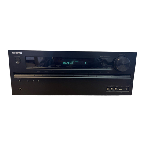
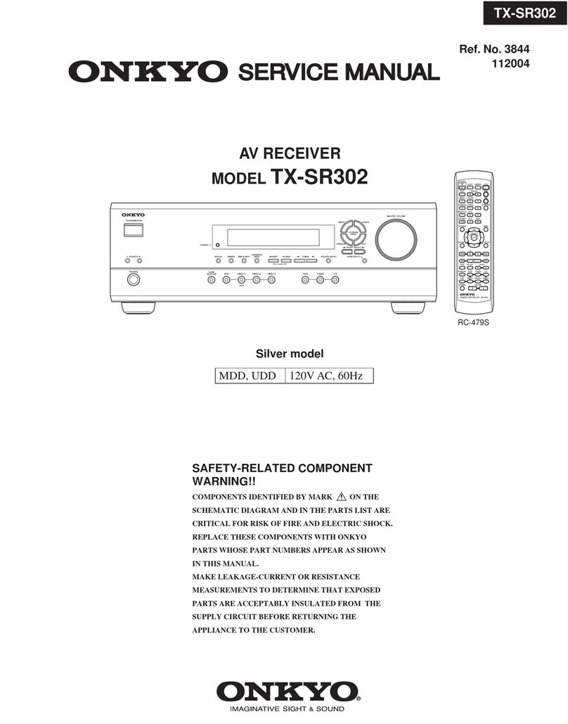
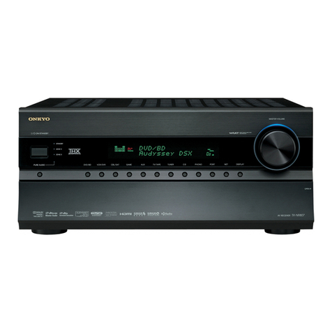
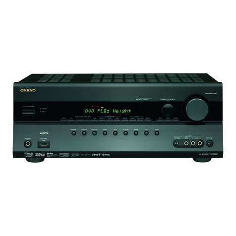
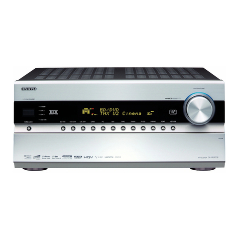
Onkyo TX-NR901 User manual

TX-NR901
SERVICE MANUAL
SERVICE MANUAL
AV RECEIVER
Black and Golden models
MODEL TX-NR901
Ref. No. 3786
112003
BMDD,BMDC 120V, AC 60Hz
GMWT,GMWR 120/220~230V, AC 50/60Hz
BMPA,GMPA 230~240V, AC 50Hz
GMGK 220V, AC 50Hz
--
/
---
@.
-
'
/ ABC DEF
PQRS TUV WXYZ
DIRECT TUNING
GHI JKL MNO
CAPS DELETE
LANGUAGE LOCATION
ALBUM AR
TIST GENRE
PLAYLIST
CUSTOM
DISPLAY
DIMMER
T
V
INPUT
SLEEP
RANDOMREC
STEP
/
SLOW
MUTING
ENTER
LAST MANGLE
SUBTITLE
AUDIO
MEMORY
SEARCHA-BREPEAT
ON STANDBY TV
TV CH
TV VOL
A
U
D
I
O
A
D
J
E
X
I
T
G
U
I
D
E
+10 0
CLEAR
123
456
789
INPUT
T
O
P
M
E
N
U
M
E
N
U
S
E
T
U
P
R
E
T
U
R
N
ZONE
2
INPUTMODE
MACRO
VOL
CH
DISC
TEST T
O
NE
CH SEL
PURE A
SURR
DIRECT
STEREO
Re-EQ
THX All ST
LEVEL
+
LEVEL
-
L NIGHT
AUDIO
SEL
DSP DSP
+
-
+
-
STANDBY/ON
STANDBY
MASTER VOLUME
TUNER PHONO NET AUDIOC
D
TAPE
DVD VIDEO
3
VIDEO
5
VIDEO
4
VIDEO
2
VIDEO
1
VCR
2
VCR
1
ZONE
2
()
GRN
REC()
RED
AUDIO
SELECTOR DISPL
AY
PURE AUDIO UPSAMPLING
PUSH TO OPEN
SAFETY-RELATED COMPONENT
WARNING!!
COMPONENTS IDENTIFIED BY MARK ON THE
SCHEMATIC DIAGRAM AND IN THE PARTS LIST ARE
CRITICAL FOR RISK OF FIRE AND ELECTRIC SHOCK.
REPLACE THESE COMPONENTS WITH ONKYO
PARTS WHOSE PART NUMBERS APPEAR AS SHOWN
IN THIS MANUAL.
MAKE LEAKAGE-CURRENT OR RESISTANCE
MEASUREMENTS TO DETERMINE THAT EXPOSED
PARTS ARE ACCEPTABLY INSULATED FROM THE
SUPPLY CIRCUIT BEFORE RETURNING THE
APPLIANCE TO THE CUSTOMER.

TX-NR901/E
SPECIFICATIONS
Amplifier Section
Video Section
Tuner Section
FM
AM
General
Video Inputs
Video Outputs
Audio Inputs
Audio Outputs
Other Sockets
Specificationsandfeaturesare subjectto changewithout
notice.
Power output:
All channels: 110 W(8 , 20 Hz–20 kHz, FTC)
(American Model)
180 W(6 , 1 kHz, EIAJ) (Asian Model)
150 W(6 , 1 kHz, DIN)
(Australian model)
Dynamic power: 2 x 280W (3 , front)
2 x 220W (4 , front)
2 x 140W (8 , front)
THD (total harmonic
distortion): 0.08% (rated power)
Damping factor: 60
Input sensitivity and
impedance: 200 mV/50k (LINE)
2.5 mV/50k (PHONO MM)
Output level and
impedance: 200 mV/470 (REC OUT)
Phono overload: 120 mV (MM, 1 kHz, 0.5%)
Frequency response: 10 Hz–100 kHz/+1 dB, –3 dB (CD,
Direct)
Tone control: ±10 dB, 50 Hz (BASS)
±10 dB, 20,000 Hz (TREBLE)
S/N ratio (Direct mode):110 dB (LINE, IHF-A, 0.5V input)
80 dB (PHONO, IHF-A, 5 mV input)
Speaker impedance: 4–16
Input sensitivity, output
level and impedance: 1.0Vp-p/75 (component and S-Video
Y)
0.7 Vp-p/75 (component PB/CB, PR/CR)
0.286 Vp-p/75 (S-Video C)
1.0 Vp-p/75
(composite)
Component video
frequency response: 5 Hz–50 MHz
Tuning frequency range:87.5–108.0 MHz
Usable sensitivity: FM STEREO 17.2 dBf, 2.0 µV (75
IHF)
FM MONO 11.2 dBf, 1.0 µV (75 IHF)
S/N ratio: FM STEREO 70 dB (IHF-A)
FM MONO 76 dB (IHF-A)
THD: FM STEREO 0.3%
FM MONO 0.2%
FM stereo separation: 45 dB at 1 kHz, 30 dB at 100 Hz–10 kHz
Tuning frequency range:530–1710 kHz (American model)
522–1611 kHz (Other models)
Usable sensitivity: 30 µV
S/N ratio: 40 dB
THD: 0.7%
Power supply: American model:AC120V, 60 Hz
Australian model:AC 230–240V, 50 Hz
Others models:AC 220–230V and 120V
switchable 50/60 Hz
Power consumption: American model: 9.0A
Australian and Worldwide models: 670W
Standby power
consumption: 2.5 W
Dimensions
(W x H x D): 17-1/8" x 6-7/8" x 18-1/16"
(435 x 175 x 459 mm)
Weight: American and Australian models:
42.5 Ibs. (19.3 kg)
Worldwide models: 42.3lbs. (19.2 kg)
Component video inputs: 2 (Input 1, Input 2)
S-Video inputs: 6 (DVD, Video 1–5)
Video inputs: 6 (DVD, Video 1–5)
Component video
outputs: 1 (Component Monitor Out)
S-Video outputs: 3 (Video 1 Out,Video 2 Out,Video
Monitor Out)
Video outputs: 4 (Video 1 Out,Video 2 Out,Video
Monitor Out, Zone 2 Video Out)
Digital inputs: 8 (Optical 1–4, Optical Video 5 (fixed, on
front panel), Coaxial 1–3)
Analog inputs: 8 (CD, Phono,Tape, DVD,Video 1–4,
Video 5)
Multichannel analog
inputs: 7.1 ch (Front L/R, Center, Surround L/R,
Surround Back L/R, Subwoofer)
Digital outputs: 2 optical
Analog outputs: 4 (Tape Out,Video 1 Out,Video 2 Out,
Zone 2 Out)
Pre outs: 8 (Front L/R, Center , Surround L/R,
Surround Back L/R or Zone 2 L/R,
Subwoofer)
Subwoofer pre out: 1
Speaker outputs: 7
Phones: 1
RS-232: 1 (not American and Australian models)
IR in/out: 1
12V trigger out: 1
Ethernet (Net-Tune) 1 (10Base-T, RJ45)

TX-NR901
SERVICE PROCEDURES 1
1. Replacing the fuses
This symbol located near the fuses indicates
that the fuse used is fast operating type.For continued
protection against fire hazard, replace with same type fuse.
For fuse rating refer to the marking adjacent to the symbol.
Ce symbole indique que le fusible utlise est a
rapide.Pour une protection permanente, n'untiliser que
fusibles de meme type. Ce darnier est la qu le present
symbol est appse.
2.To initialize the unit
This device employs a microprocessor to perform various
functions and operations.If interference generated by an
external power supply, radio wave, or other electrical source
results in accident which causes the specified operations
and functions to operate abnormally.
To perform a result, please follow the procedure below.
1.Press the STANDBY ON button to turn on the unit.
2.Press and hold down the VIDEO 1 button, then press the
STANDBY/ON button.
3.After "CLEAR" is displayed, the preset memory and each
mode stored in the memory, such as surround, are
initialized and will return to the factory setting.
4.Unplug the power supply cord.
3. Safety-check out
(Only U.S.A. model)
After correcting the original service problem, perform the
following safety check before releasing the set to the
customer. Connect the insulating-resistance tester between
the plug of power supply cord and screw on the back panel.
Specifications: 3.3Mohm+/-10% at 500V.
4. Memory Preservation
This unit does not require memory preservation batteries.A
built-in memory power back-up system preserves the contents
of the memory during power failures and even when the unit is
unplugged.The unit must be plugged in order to charge the
back-up system.
The memory preservation period after the unit has been
unplugged varies depending on climate and placement of the
unit. On the average, memory contents are protected over a
period of a few weeks after the last time the unit has been
unplugged.This period is shorter when the unit is exposed to a
highly humid climate.
5.Setting the voltage selector
(Worldwide models only)
Worldwide models are equipped with a voltage selector so
that you
supplies. Be
can set your TX-NR901 to conform with local power
sure to set this switch to match the voltage of
your area before plugging in the unit.
Determine the proper voltage for your area: 220-230 V or
the preset voltage is not correct for your area,
into the groove in the switch and slide
(220-230 V), whichever is appropriate.
Note: <D>: 120V model only
<A>: Australian model only
<T>: Worldwide model only
<R>: Chinese model only
the power supply in
120 V. If
insert a screwdriver
the switch all the way to the top (120 V) or bottom
REF. NO. PART NO. DESCRIPTION
F901 252196 12A-UL/T-314,Fuse <D/T/R>
F902 252078 5A-SE-EAK,
252244 or 5A-SE-TL250V or
252278 5A-SE-TL250V, Fuse <T/A/R/K>
F903 252164 or 5A-UL/T-237 or
252258 5A-T/UL-ST2,Fuse <D>
252075, 2.5A-SE-EAK,
252241 or 2.5A-SE-TL250V or
252275 2.5A-SE-TL250V,Fuse <T/A/R/K>
F9501,F9502 252160 or 2.5A-UL/T-237 or
252254 2.5A-T/UL-ST2,Fuse <D>
252075, 2.5A-SE-EAK,
252241 or 2.5A-SE-TL250V or
252275 2.5A-SE-TL250V,Fuse <T/A/R/K>
F9503,F9504 252158 or 1.6A-UL/T-237 or
252252 1.6A-T/UL-ST2,Fuse <D>
252073, 1.6A-SE-EAK,
252239 or 1.6A-SE-TL250V or
252273 1.6A-SE-TL250V,Fuse <T/A/R/K>
<K>: Korean model only
FM
75
OUT
OUT
OUT
OUT
L
OUT
PHONO
DIGITAL
IN
PRE OUT
DIGITAL
OUT
OPT
OPT
2
1
2
3
4
1
2
FRONT
SUB
SURR
RL
AUDIO
RL
CD
TAPE
RL
AUDIO VIDEO S VIDEO
MONITOR
OUT
RL
IN
IN
IN
IN
IN
IN
IN
ZONE 2
DVD
VIDEO 1
VIDEO 2
VIDEO 3
VIDEO 4
AUDIO AUDIO VIDEO SVIDEO
1
3
GND
SURR
BACK/
ZONE 2
RL
IN
AC
INLET
COAX
R
ZONE 2
REMOTE
CONTROL
RS232
I
R
12V TRIGGER OUT
IN
CENTER
ETHERNET
(Net -Tune)
RL
MULTI CH
INPUT
FRONT
SUB
SURR
SURR
BACK
CENTER
RL
AM
ANTENNA
COMPONENT
VIDEO
Y
PB
PR
OUTPUT
INPUT 1
Y
PB
PR
INPUT 2
Y
PB
PR
VOLTAGE
SELECTOR
220-230V
120V
TX-NR
901
MODEL NO.
/
SURR
BACK/
ZONE 2
SPEAKERS
FRONT SPEAKERS LRL R
SURR SPEAKERS
CENTER
SPEAKER
RL
VOLTAGE
SELECTOR
220-230V
120V

TX-NR901
SERVICE PROCEDURES 2
This section explains how to specify the AM frequenc y
step. (This setting is not available on American and Aus-
tralian models.)
Note:
* This procedure can also be performed by using the
TX-NR901's [SETUP] button, [ ]/[ ]/[ ]/[ ]
buttons, and [ENTER] button.
Specifying the AM Frequency Step
(Worldwide model only)
1Press the scroll wheel, and then
press the [SETUP] button.
The main menu appears onscreen.
2Use the Up/Down [ ]/[ ] but-
tons to select"0. Hardware
Setup," and then press the
[ENTER] button.
The Hardware Setup menu appears.
3Use the Up/Down [ ]/[ ] but-
tons to select"5. AM Frequency
Step," and then press the
[ENTER] button.
The AM Frequency Step menu appears.
4Use the Up/Down [ ]/[ ] but-
tons to select"a. Frequency
Step,"andthenusethe Left/Right
[ ]/[ ] buttons to select:
10 kHz: Select if 10 kHz steps are
used in your area.
9 kHz: Select if 9kHz steps are used
in your area.
5Press the [SETUP] button.
The setup menu closes.
ENTER
ENTER
ENTER
ENTER
0-5.AM Frequency Step
a.Frequency Step
:9 kHz
Quit:[SETUP]
ENTER

TX-NR901
FRONT PANEL
4 6 7
12
11
13 16 19 21
5 8 9
10
15
14 1718 20
3
26
23
22 25
24
2
27 2928 30
STANDBY/ON
STANDBY
MASTER VOLUME
TUNER PHONO NET AUDIOC
D
TAPE
DVD VIDEO
3
VIDEO
5
VIDEO
4
VIDEO
2
VIDEO
1
VCR
2
VCR
1
ZONE
2
()
GRN
REC()
RED
AUDIO
SELECTOR DISPL
AY
PURE AUDIO UPSAMPLING
OFF
ON
POWER
PUSH TO OPEN
PHONES
ZONE
2
LEVEL
STEREO SURROUND
THX DSPREC OUT ZONE
2
OFF DIMMER
MEMORY FM MODE
SETUP ENTER
RETURN
S VIDEO VIDEO
DIGITAL
VIDEO
5
INPUT
STANDBY/ON
STANDBY
MASTER VOLUME
TUNER PHONO NET AUDIOC
D
TAPE
DVD VIDEO
3
VIDEO
5
VIDEO
4
VIDEO
2
VIDEO
1
VCR
2
VCR
1
ZONE
2
()
GRN
REC()
RED
AUDIO
SELECTOR DISPL
AY
PURE AUDIO UPSAMPLING
PUSH TO OPEN
PRESET
TUNING
CLEAR AUDIO
LR
American and Australian Models
Other Models
Front door Push here to open the flap
4 6 7
12
11
5 8 9
10
3
1
2

TX-NR901
FRONT PANEL
POWER switch
American and Australian models don’t have this
switch.
This is the main power switch.When set to OFF, the
TX-NR901 is completely shutdown.When set to
ON, the TX-NR901 is in Standby mode and the
STANDBY indicator lights up.
Don’t turn on the power until you’vecompleted,
and double checked all connections.
STANDBY/ON button
This button is used to set the TX-NR901 to On or
Standby. For models with a POWER switch, this
button has no effect unless the POWER switch is set
to ON.
STANDBY indicator
This indicator lights up when the TX-NR901 is in
Standby mode, and it ashes while a signal is being
received from the remote controller.
AUDIO SELECTOR button
This button is used to select the audio input signal
format: analog, digital, or multichannel.
Input selector buttons & indicators
These buttons are used to select the following input
sources: DVD, VIDEO 1–5,TAPE,TUNER,
PHONO, CD, and NET AUDIO.The indicators
show the currently selected input source.
The indicators also show which input source is
selected for Zone 2, in which case they light up
green, or which input source is selected for record-
ing (REC OUT), in which case they light up red.
Display
See “Display” on next page.
Remote-control sensor
This sensor receives control signals from the remote
controller.
DISPLAY button
This button is used to display various information
about the currently selected input source.
MASTERVOLUME control
This control is used to set the volume of the
TX-NR901 from 0 to 100.
DIRECT/PURE AUDIO button
This button is used to select the Direct or Pure
Audio listening modes.
PURE AUDIO indicator
This indicator lights up when the Pure Audio listen-
ing mode is selected.
UPSAMPLING indicator
This indicator lights up when the Upsampling func-
tion is on.
PHONES jack
This 1/4-inch phone jack is for connecting a stan-
dard pair of stereo headphones for private listening.
ZONE 2 LEVEL [ ] [ ] buttons
These buttons are used to set the volume for Zone 2.
REC OUT button
This button is used to select the input source that
you want to record via the REC OUTs (i.e., TAPE
OUT,VIDEO 1 OUT,VIDEO 2 OUT).
ZONE 2 button
This button is used to select the input source for
Zone 2.
OFF button
This button is used to turn off the REC OUTs (i.e.,
TAPE OUT,VIDEO 1 OUT,VIDEO 2 OUT) or
Zone 2.
STEREO button
This button is used to select the Stereo listening
mode.
SURROUND button
This button is used to select the Dolby and DTS lis-
tening modes.
THX button
This button is used to select the THX listening
modes.
DSP [ ] [ ] buttons
These buttons are used to select the DSP (digital
signal processor) listening modes.
DIMMER button
This button is used to adjust the display brightness.
MEMORY button
This button is used when storing and deleting radio
presets.
FM MODE button
This button is used to select the FM radio Auto and
Mono modes.
SETUP button
This button is used to access the onscreen setup
menus (OSD) that appear on the TV.
TUNING [ ] [ ] buttons
These buttons are used to tune into radio stations
and to select items on the onscreen setup menus
(OSD).
ENTER button
This button is used when navigating the onscreen
setup menus (OSD), entering names, and confirm-
ing settings.
PRESET [ ] [ ] buttons
These buttons are used to select radio presets and to
select items on the onscreen setup menus (OSD).
4
6
7
12
11
13
16
19
21
5
8
9
10
15
14
17
18
20
3
26
23
22
25
24
1
2
27
28

TX-NR901
FRONT PANEL
RETURN button
This button is used to return to the previously dis-
played onscreen setup menu (OSD).
VIDEO 5 INPUTs
These optical digital audio, S-Video, composite
video, and analog audio inputs can be used to con-
nect a camcorder, games console, and so on.
Audio input format indicators
These indicators show the audio input format for the
currently selected input source.
Listening mode & digital audio format
indicators
These indicators show the currently selected listen-
ing mode and digital audio format.
Tuning indicators
AUTO indicator:
This indicator lights up when the tuner is tuned to
an FM station and Stereo mode is selected. It goes
off when Mono mode is selected.
TUNED indicator:
This indicator lights up when the tuner is tuned into
an AM or FM station.
FM STEREO indicator:
This indicator lights up when the tuner is tuned to a
stereo FM station. It goes off when Mono mode is
selected.
Multipurpose display area
Normally, the name of the currently selected input
source is displayed here. When you select the AM
or FM input source, the radio frequency and preset
number are displayed. If you press the [DISPLAY]
button, the currently selected listening mode and
digital audio format are displayed.
Volume level
The volume level is displayed here.
SLEEP indicator
This indicator lights up when the Sleep function has
been set.
Display
29 30
23
45
1
6
2
3
4
5
1
6

TX-NR901
REAR PANEL
DIGITAL IN COAX 1–3, OPT 1–4
These coaxial and optical digital audio inputs can be
used to connect CD, DVD, or LD (laser disc) play-
ers and other components with digital audio outputs.
DIGITAL OUT OPT 1 & 2
These optical digital audio outputs can be used to
connect a CD recorder or other digital recorder with
digital inputs.
PRE OUT—FRONT L/R, SUB, CENTER,
SURR L/R
If you use the TX-NR901 as a preamp, these analog
audio outputs can be connected to the inputs on a
separate power amp.The SUB output is used to
connect a powered subwoofer.
FM
75
OUT
OUT
OUT
OUT
L
OUT
PHONO
DIGITAL
IN
PRE OUT
DIGITAL
OUT
OPT
OPT
2
1
2
3
4
1
2
FRONT
SUB
SURR
RL
AUDIO
RL
CD
TAPE
RL
AUDIO VIDEO S VIDEO
MONITOR
OUT
RL
IN
IN
IN
IN
IN
IN
IN
ZONE 2
DVD
VIDEO 1
VIDEO 2
VIDEO 3
VIDEO 4
AUDIO AUDIO VIDEO S VIDEO
1
3
GND
SURR
BACK/
ZONE 2
RL
IN
AC
INLET
COAX
R
ZONE 2
REMOTE
CONTROL
RS232
I
R
12V TRIGGER OUT
IN
CENTER
ETHERNET
(Net -Tune)
RL
MULTI CH
INPUT
FRONT
SUB
SURR
SURR
BACK
CENTER
RL
AM
ANTENNA
COMPONENT
VIDEO
Y
PB
PR
OUTPUT
INPUT 1
Y
PB
PR
INPUT 2
Y
PB
PR
VOLTAGE
SELECTOR
220-230V
120V
TX-NR
901
MODEL NO.
/
SURR
BACK/
ZONE 2
SPEAKERS
FRONT SPEAKERS L
RL R
SURR SPEAKERS
CENTER
SPEAKER
RL
FM
75
OUT
OUT
OUT
OUT
L
OUT
PHONO
DIGITAL
IN
PRE OUT
DIGITAL
OUT
OPT
OPT
2
1
2
3
4
1
2
FRONT
SUB
SURR
RL
AUDIO
RL
CD
TAPE
RL
AUDIO VIDEO S VIDEO
MONITOR
OUT
RL
IN
IN
IN
IN
IN
IN
IN
ZONE 2
DVD
VIDEO 1
VIDEO 2
VIDEO 3
VIDEO 4
AUDIO AUDIO VIDEO S VIDEO
1
3
GND
SURR
BACK/
ZONE 2
RL
IN
COAX
R
ZONE 2
REMOTE
CONTROL
I
R
12V TRIGGER OUT
IN
CENTER
ETHERNET
(Net -Tune)
RL
MULTI CH
INPUT
FRONT
SUB
SURR
SURR
BACK
CENTER
RL
AM
ANTENNA
COMPONENT
VIDEO
Y
PB
PR
OUTPUT
INPUT 1
Y
PB
PR
INPUT 2
Y
PB
PR
AC OUTLETS
AC
120
V 60
Hz
SWITCHED
TOTAL 120W 1A MAX.
AV RECEIVER
MODEL NO. TX-NR
901
SURR
BACK/
ZONE 2
SPEAKERS
FRONT SPEAKERS L
RL R
SURR SPEAKERS
CENTER
SPEAKER
RL
American and Australian Models
Other Models
21
1 3 4 6 7 12 11 13 16 19 26
227 5 8 9 10 15 14 17 18 23 22
21
227 58 9 10 15 14 17 18 23 22 252420
13 4 6712 11 13 16 19 26
13
2

TX-NR901
REAR PANEL
4
6
7
12
11
13
16
19
26
21
5
8
9
10
15
14
17
18
23
22
25
24
20
PRE OUT—SURR BACK/ZONE 2
These analog audio outputs can be used to feed the
L/R surround back inputs on a separate power amp
when the TX-NR901 is used as a preamp, or to feed
a power amp in Zone 2.
MULTI CH INPUT—FRONT L/R, SUB,
CENTER, SURR L/R, SURR BACK L/R
Theseanalogaudioinputscan be used to connect AV
components with multiple analog audio outputs,
including DVD players with individual 5.1/7.1 sur-
round analog audio outputs.
AM ANTENNA
These push terminals are for connecting an AM
antenna.
FM ANTENNA
This connector is for connecting an FM antenna.
PHONO IN
These analog inputs can be used to connect a turnta-
ble with a moving-magnet cartridge.
CD IN
These analog inputs can be used to connect a CD
player with analog outputs.
TAPE IN/OUT
These analog inputs and outputs can be used to con-
nect a cassette recorder , Mini Disc recorder, or other
recorder with analog inputs and outputs.
MONITOR OUT
This S-Video or composite video output can be con-
nected to the video input on your TV or projector.
ZONE 2 OUT
These composite video and analog audio outputs
can be used to feed a TV and an integrated amp in
Zone 2.
DVD IN
These S-Video, composite video, and analog audio
inputs can be used to connect a DVD player.
VIDEO 1 & 2 IN/OUT
These S-Video, composite video, and analog audio
inputs and outputs can be used to connect one or
two video recorders (e.g.,VCRs).
VIDEO 3 & 4 IN
These S-Video, composite video, and analog audio
inputs can be used to connect one or two video
sources (e.g., cableTV, satelliteTV , or a set-top
box).
COMPONENTVIDEO OUTPUT
This component video output can be used to con-
nect a TV or projector with a component video
input.
COMPONENTVIDEO INPUT 1 & 2
These component video inputs can be used to con-
nect one or twoAV components with component
video outputs, such as a DVD player.
ETHERNET (Net-Tune)
This port is for connecting the TX-NR901 to your
Ethernet network (i.e., router or switch) for use with
Net-Tune (i.e., Internet radio and MP3, WAV, and
WMA playback).
SPEAKERS
These terminal posts are for connecting your speak-
ers.The SURR BACK/ZONE 2 terminals can be
used with surround back speakers in the main room
or speakers in another room (Zone 2).
RS232
This port is for connecting the TX-NR901 to home
automation and external controllers.
American and Australian models don't have this
port.
IR IN/OUT
If you want to use the remote controller to control
the TX-NR901 from Zone 2, or if the TX-NR901 is
installed in a cabinet and the line of sight between
the TX-NR901 and the remote controller is
obstructed, a commercially available IR receiver
can be connected to the IR IN.A commercially
available IR emitter can be connected to the IR
OUT to pass the IR signals along to another AV
component.
ZONE 2 12VTRIGGER OUT
This output can be connected to the 12-volt trigger
input on a power amp in Zone 2.The power amp
can then be turned on or off automatically from the
TX-NR901.
REMOTE CONTROL
This (Remote Interactive) socket can be con-
nected to the socket on another OnkyoAV com-
ponent.The TX-NR901’ s remote controller can
then be used to control that component.To use ,
you must make an analog RCA/phono audio con-
nection between the TX-NR901 and the other AV
component, even if they are connected digitally .
AC INLET
The supplied power cord should be connected here.
American and Australian models do not have anAC
INLET.They have an integral power cord instead.
VOLTAGE SELECTOR
This voltage selector provides compatibility with
power systems around the world.
American and Australian models don’ t havethis
selector.
AC OUTLETS
These switched AC outlets can be used to supply
power to other AV components. The connector type
depends on the country in which you purchased
your TX-NR901.
Grounding screw
This screw is for connecting a turntable’ s ground
wire.
27
TX-NR901
REMOTE CONTROLLER
4
6
7
12
11
13
16
19
21
5
8
9
10
15
14
17
18
20
The TX-NR901’s remote controller is a multipurpose
devicethatcan be usedto controlnot justthe TX-NR901
but your other AV components as well. This section
explains how it’s various operating modes can be used to
control the TX-NR901 and various -compatible
Onk yo components.
Amp mode is used to control the TX-NR901.To select
Amp mode, press the scroll wheel. “ AMP” appears
on the display.
Note:
Whileneither the [INPUT] buttonnor [MODE] buttonis
illuminated, rolling the scroll wheel changes the input
source and remote controller mode simultaneously.
Boxed numbers are for Net-Tune mode.
ON button
This button is used to turn on the TX-NR901.
STANDBY button
This button is used to set the TX-NR901 to Standby.
Number/letter buttons
These buttons are used to enter numbers and letters.
CUSTOM button
This button is used to access various settings that
you can use to customize the operation of the
remote controller.
MACRO button
This button is used with the Macro function.
MODE button
This button is used with the scroll wheel to select
the remote controller modes.
DIMMER button
This button is used to adjust the display brightness.
Up/Down/Left/Right [ ]/[ ]/[ ]/[ ] &
ENTER buttons
These buttons are used to select items on the
onscreen setup menus (OSD).The ENTER button is
also used to enter names and to confirm settings.
CH/DISC button
This button is used to select radio presets.
RETURN/EXIT button
This button is used to return to the previously dis-
played onscreen setup menu (OSD).
DISPLAY button
This button is used to display various information
about the currently selected input source.
THX button
This button is used to select the THX listening
modes.
SURR button
This button is used to select the Dolby and DTS lis-
tening modes.
DIRECT button
This button is used to select the Direct listening
mode.
PURE A button
This button is used to select the Pure Audio listen-
ing mode.
Amp Mode
--
/
---
@.
-
'
/ ABC DEF
PQRS TUV WXYZ
DIRECT TUNING
GHI JKL MNO
CAPS DELETE
LANGUAGE LOCATION
ALBUM AR
TIST GENRE
PLAYLIST
CUSTOM
DISPLAY
DIMMER
T
V
INPUT
SLEEP
RANDOMREC
STEP
/
SLOW
MUTING
ENTER
LAST MANGLE
SUBTITLE
AUDIO
MEMORY
SEARCHA-BREPEAT
ON STANDBY TV
TV CH
TV VOL
A
U
D
I
O
A
D
J
E
X
I
T
G
U
I
D
E
+10 0
CLEAR
123
456
789
INPUT
T
O
P
M
E
N
U
M
E
N
U
S
E
T
U
P
R
E
T
U
R
N
ZONE
2
INPUTMODE
MACRO
VOL
CH
DISC
TEST T
O
NE
CH SEL
PURE A
SURR
DIRECT
STEREO
Re-EQ
THX All ST
LEVEL
+
LEVEL
-
L NIGHT
AUDIO
SEL
DSP DSP
+
-
+
-
2
3
4
5
1
98
10
11
12
6
7
Scroll wheel
3
1
2
4
6
7
12
11
13
26
5
8
9
10
15
14
23
22
25
24
3
1
2
27
29
28
30
31
13
14
15
16
17
18 19
20

TX-NR901
REMOTE CONTROLLER
26
23
22
25
24
27
16
19
21
17
18
20
TESTTONE, CH SEL, LEVEL– & LEVEL+
buttons
These buttons are used to adjust the level of each
speaker individually. These functions can be set
only with the remote controller.The [LEVEL–] and
[LEVEL+] buttons are also used to adjust the vol-
ume in Zone 2.
AUDIO SEL button
This button is used to select the audio input signal
format: analog, digital, or multichannel.
LIGHT button
This button is used to turn on or off the remote con-
troller’s illuminated buttons.
DIRECTTUNING button
This button is used with the number buttons to
select a radio station by entering its frequency.Press
this button first, and then use the number buttons to
enter the frequency.
Display
The top line of this LCD display shows the name of
the currently selected input source.The bottom line
shows the currently selected remote controller
mode.
ZONE 2 button
This button is used when you want to set the volume
and input source for Zone 2.
INPUT button
This button is used to select the input source. Press
this button first, and then roll the scroll wheel until
the name of the input source appears on the display.
SLEEP button
This button is used to set the Sleep function.This
function can be set only with the remote controller.
VOL button
This button is used to set the volume of the
TX-NR901.
SETUP/GUIDE button
This button is used to access the onscreen setup
menus (OSD) that appear on the TV.
MUTING button
This button is used to mute the TX-NR901.This
function can be set only with the remote controller.
All ST button
This button is used to select the All Ch Stereo listen-
ing mode.
STEREO button
This button is used to select the Stereo listening
mode.
[ DSP] & [DSP ] buttons
These buttons are used to select the DSP (digital
signal processor) listening modes.
Re-EQ button
This button is used to turn on and off the Re-EQ
function.
L NIGHT button
This button is used to set the Late Night function.
Net-Tune mode is used with the Net-Tune functions.To
select Net-Tune mode, press the [MODE] button, and
then roll the scroll wheel until “NET -T” appears on
the display.
Note:
Whileneither the [INPUT] button nor [MODE] buttonis
illuminated, the scroll wheel changes the input source
andremote controller mode simultaneously.(e.g.,setthe
input source to “MSRV/IRD” and the mode to
“NET-T.”)
Number/letter buttons
These buttons are used to enter numbers and letters
when searching for music in your Net-Tune Central
music library.
MODE button
This button is used with the scroll wheel to select
the remote controller modes. Press this button first,
and then roll the scroll wheel until “NET -T”
appears on the display.
Up/Down/Left/Right [ ]/[ ]/[ ]/[ ] &
ENTER buttons
These buttons are used to navigate Internet radio
and Net-Tune server menus.The ENTER button is
used to confirm items and to start playback of Net-
Tune server tracks.
CH/DISC button
This button is used to select Internet radio presets.
Play [ ] button
This button is used to start playback of Net-Tune
server tracks.
Previous/Next [ ]/[ ] buttons
The Previous [ ]button is used to select the pre-
vious track. During playback it selects the begin-
ning of the current track.The Next [ ] button is
used to select the next track.
Pause [ ] button
This button is used to pause playback.
REPEAT button
This button is used for repeat playback.
ALBUM button
This button is used to search your Net-Tune Central
music library by album.
PLAYLIST button
This button is used to search your Net-Tune Central
library by playlist.
Net-Tune Mode
28
29
30
31
2
3
4
5
1
9
8
10
6
7

TX-NR901
REMOTE CONTROLLER
CAPS button
This button is used to select lowercase letters,
uppercase letters, and numbers when searching for
Net-Tune Central music by album, artist, or playlist.
DELETE button
This button is used to delete characters entered with
the number/letter buttons.
INPUT button
This button is used to select the input source. Press
this button first, and then roll the scroll wheel until
“MSRV” (Music Server—Net-Tune Central) or
“IRD” (Internet Radio) appears on the display.
FR/FF [ ]/[ ] buttons
The FR [ ] button is used to start fast reverse. The
FF [ ] button is used to start fast forward.
Stop [ ] button
This button is used to stop playback.
RANDOM button
This button is used for random playback.
ARTIST button
This button is used to search your Net-Tune Central
music library by artist.
GENRE button
This button is used to search your Net-Tune Central
music library by genre, and to search for Internet
radio stations by genre.
LOCATION button
This button is used to search for Internet radio sta-
tions by country.
LANGUAGE button
This button is used to search for Internet radio sta-
tions by language.
Connecting your -compatible Onk yo DVD player,
CDplayer,MiniDisc recorder, orcassette recorder tothe
TX-NR901’s socketallows you tocontrol itwith the
TX-NR901’s remote controller.You only need to point
the remote controller at the TX-NR901.
Touse the function, you must make an connec-
tion and an analog RCA/phono audio connection
betweenthe AV componentand your TX-NR901,evenif
they are connected digitally.
DVDmode is usedtocontrol anOnkyoDVD playercon-
nected to the TX-NR901 via .Toselect DVD mode,
press the [MODE] button, and then roll the scroll
wheel until “DVD” appears on the display.
Note:
Whileneither the [INPUT]button nor [MODE]button is
illuminated, the scroll wheel changes the input source
and remote controller mode simultaneously (e.g., set the
input source and mode to “DVD.”)
ON button
This button is used to turn on the DVD player.
STANDBY button
This button is used to set the DVD player to
Standby.
Number/letter buttons
These buttons are used to enter title, chapter, and
track numbers and to enter times for locating spe-
cific points in time.
MODE button
This button is used with the scroll wheel to select
the remote controller modes. Press this button first,
and then roll the scroll wheel until “DVD” appears
on the display.
TOP MENU button
This button is used to select a DVD’ s top menu.
Up/Down/Left/Right [ ]/[ ]/[ ]/[ ] &
ENTER buttons
These buttons are used to navigate DVD menus and
the DVD player’s onscreen setup menus. The
ENTER button is used to start playback of the
selected menu title, chapter, or track and to confirm
settings.
CH/DISC button
This button is used to select discs on a D VD
changer.
RETURN/EXIT button
This button is used to exit the D VD player’ s
onscreen setup menu and to restart menu playback.
DISPLAY button
This button is used to display information about the
current disc, title, chapter, or track, including the
elapsed time, remaining time, total time, and so on.
Previous/Next [ ]/[ ] buttons
The Previous [ ] button is used to select the pre-
vious chapter or track. During playback it selects
the beginning of the current chapter or track. The
Next [ ] button is used to select the next chapter
or track.
FR/FF [ ]/[ ] buttons
The FR [ ] button is used to start fast reverse.The
FF [ ] button is used to start fast forward.
Pause [ ] button
This button is used to pause DVD playback.
STEP/SLOW [ ]/[ ] buttons
These buttons are used for frame-by-frame playback
and slow-motion playback.
SUBTITLE button
This button is used to select subtitles.
DVD Mode
6
7
12
11
13
5
8
9
10
14
4
11
12 3
1
2
13
14
15
16
17
18
19
20

TX-NR901
REMOTE CONTROLLER
AUDIO button
This button is used to select foreign language
soundtracks and audio formats (e.g., Dolby Digital
or DTS).
REPEAT button
This button is used to set the repeat playback func-
tions.
A-B button
This button is used to set the A–B repeat playback
function.
Open/Close [ ] button
This button is used to open and close the disc tray.
LIGHT button
This button is used to turn on or of f the remote con-
troller’s illuminated buttons.
INPUT button
This button is used to select the input source. Press
this button rst, and then roll the scroll wheel until
“DVD” appears on the display.
MENU button
This button is used to select a DVD’s menu.
VOL button
This button is used to set the volume of the
TX-NR901.
SETUP/GUIDE button
This button is used to access the DVD player’s
onscreen setup menus.
MUTING button
This button is used to mute the TX-NR901.This
function can be set only with the remote controller.
Play [ ] button
This button is used to start DVD playback.
Stop [ ] button
This button is used to stop DVD playback.
RANDOM button
This button is used with the random playback func-
tion.
ANGLE button
This button is used to select different camera angles.
LAST M button
This button is used with the last memory function,
which allows you to resume DVD playback from
where you left off.
MEMORY button
This button is used with the memory playback func-
tion, which allows you to create a custom playlist of
titles, chapters, or tracks.
SEARCH button
This button is used to search for titles, chapters,
tracks, and specific points in time.
CLEAR button
This button is used to cancel functions and to clear
entered numbers.
--
/
---
@.
-
'
/ ABC DEF
PQRS TUV WXYZ
DIRECT TUNING
GHI JKL MNO
CAPS DELETE
LANGUAGE LOCATION
ALBUM AR
TIST GENRE
PLAYLIST
CUSTOM
DISPLAY
DIMMER
T
V
INPUT
SLEEP
RANDOMREC
STEP
/
SLOW
MUTING
ENTER
LAST MANGLE
SUBTITLE
AUDIO
MEMORY
SEARCHA-BREPEAT
ON STANDBY TV
TV CH
TV VOL
A
U
D
I
O
A
D
J
E
X
I
T
G
U
I
D
E
+10 0
CLEAR
123
456
789
INPUT
T
O
P
M
E
N
U
M
E
N
U
S
E
T
U
P
R
E
T
U
R
N
ZONE
2
INPUTMODE
MACRO
VOL
CH
DISC
TEST T
O
NE
CH SEL
PURE A
SURR
DIRECT
STEREO
Re-EQ
THX All ST
LEVEL
+
LEVEL
-
L NIGHT
AUDIO
SEL
DSP DSP
+
-
+
-
Scroll wheel
4
6
7
12
11
13
16
19
21
5
8
9
10
15
14
17
18
32
3
26
23
22
25
24
1
2
27
29
28
30
31
16
21
17
18
20
23
22
25
24
27
29
28
30
31
15
20
32
19
26

TX-NR901
REMOTE CONTROLLER
CD mode is used to control an Onkyo CD player con-
nected to the TX-NR901 via .To select CD mode,
press the [MODE] button, and then roll the scroll
wheel until “CD” appears on the display.
Note:
Whileneither the [INPUT] button nor [MODE] buttonis
illuminated, the scroll wheel changes the input source
and remote controller mode simultaneously (e.g., set the
input source and mode to “CD.”)
Boxed numbers are for MiniDisc mode .
ON button
This button is used to set the CD player to On or
Standby.
Number/letter buttons
These buttons are used to enter track numbers and
to enter times for locating specific points in time.
MODE button
This button is used with the scroll wheel to select
the remote controller modes. Press this button first,
and then roll the scroll wheel until “CD” appears on
the display.
CH/DISC button
This button is used to select discs on a CD changer.
DISPLAY button
This button is used to display information about the
current disc or track, including the elapsed time,
remaining time, total time, and so on.
Previous/Next [ ]/[ ] buttons
The Previous [ ] button is used to select the pre-
vious track. During playback it selects the begin-
ning of the current track. The Next [ ] button is
used to select the next track.
FR/FF [ ]/[ ] buttons
The FR [ ] button is used to start fast reverse.The
FF [ ] button is used to start fast forward.
Pause [ ] button
This button is used to pause CD playback.
REPEAT button
This button is used to set the repeat playback func-
tions.
Open/Close [ ] button
This button is used to open and close the disc tray.
LIGHT button
This button is used to turn on or off the remote con-
troller’s illuminated buttons.
INPUT button
This button is used to select the input source. Press
this button rst, and then roll the scroll wheel until
“CD” appears on the display.
VOL button
This button is used to set the volume of the
TX-NR901.
MUTING button
This button is used to mute the TX-NR901.This
function can be set only with the remote controller.
Play [ ] button
This button is used to start CD playback.
Stop [ ] button
This button is used to stop CD playback.
CD Mode
--
/
---
@.
-
'
/ ABC DEF
PQRS TUV WXYZ
DIRECT TUNING
GHI JKL MNO
CAPS DELETE
LANGUAGE LOCATION
ALBUM AR
TIST GENRE
PLAYLIST
CUSTOM
DISPLAY
DIMMER
T
V
INPUT
SLEEP
RANDOMREC
STEP
/
SLOW
MUTING
ENTER
LAST MANGLE
SUBTITLE
AUDIO
MEMORY
SEARCHA-BREPEAT
ON STANDBY TV
TV CH
TV VOL
A
U
D
I
O
A
D
J
E
X
I
T
G
U
I
D
E
+10 0
CLEAR
123
456
789
INPUT
T
O
P
M
E
N
U
M
E
N
U
S
E
T
U
P
R
E
T
U
R
N
ZONE
2
INPUTMODE
MACRO
VOL
CH
DISC
TEST T
O
NE
CH SEL
PURE A
SURR
DIRECT
STEREO
Re-EQ
THX All ST
LEVEL
+
LEVEL
-
L NIGHT
AUDIO
SEL
DSP DSP
+
-
+
-
9
Scroll wheel
6
7
12
11
13
16
19
5
8
9
10
15
14
17
18
4
2
3
4
5
1
8
10
11
12
6
7
3
1
2
13
14
15
16
17
18
19
6
7
5
8
9
10
4
3
1
2
12
11
13
16
15
14

TX-NR901
REMOTE CONTROLLER
RANDOM button
This button is used with the random playback func-
tion.
MEMORY button
This button is used with the memory playback func-
tion, which allows you to create a custom playlist of
tracks.
CLEAR button
This button is used to cancel functions and to clear
entered numbers.
MiniDisc mode is used to control an Onkyo MiniDisc
recorder connected to the TX-NR901 via .Toselect
MiniDisc mode, pr ess the [MODE] button, and then
roll the scroll wheel until "MD" appears on the dis-
play.
Note:
Whileneither the [INPUT] button nor [MODE]button is
illuminated, the scroll wheel changes the input source
and remote controller mode simultaneously (e.g., set the
input source and mode to "MD.")
ON button
This button is used to set the MiniDisc recorder to
On or Standby.
Number/letter buttons
These buttons are used to enter track numbers and
to enter times for locating specific points in time.
MODE button
This button is used with the scroll wheel to select
the remote controller modes. Press this button first,
and then roll the scroll wheel until "MD" appears on
the display.
DISPLAY button
This button is used to display information about the
current disc or track, including the elapsed time,
remaining time, total time, and so on.
Previous/Next [ ]/[ ] buttons
The Pre vious [ ] button is used to select the pre-
vious track. During playback it selects the begin-
ning of the current track.The Next [ ] button is
used to select the next track.
FR/FF [ ]/[ ] buttons
The FR [ ] button is used to start fast reverse.The
FF [ ] button is used to start fast forward.
Pause [ ] button
This button is used to pause MiniDisc playback.
REC [ ] button
This button is used to start MiniDisc recording.
9REPEAT button
This button is used to set the repeat playback func-
tions.
Eject [ ] button
This button is used to set eject the MiniDisc.
LIGHT button
This button is used to turn on or off the remote con-
troller's illuminated buttons.
INPUT button
This button is used to select the input source. Press
this button first, and then roll the scroll wheel until
"MD" appears on the display.
VOL button
This button is used to set the volume of the
TX-NR901.
MUTING button
This button is used to mute the TX-NR901. This
function can be set only with the remote controller.
Play [ ] button
This button is used to start MiniDisc playback.
Stop [ ] button
This button is used to stop MiniDisc playback.
RANDOM button
This button is used with the random playback func-
tion.
MEMORY button
This button is used with the memory playback func-
tion, which allows you to create a custom playlist of
tracks.
CLEAR button
This button is used to cancel functions and to clear
entered numbers.
MiniDisc Mode
19
17
18
2
3
4
5
1
8
10
11
12
6
7
13
14
15
16
17
18
19

TX-NR901
REMOTE CONTROLLER
Tape mode is used to control an Onkyo cassette recorder
connected to the TX-NR901 via . To select Tape
mode, press the scroll wheel. "AMP" appears on the
display.
Note:
Whileneither the [INPUT] buttonnor [MODE] button is
illuminated, the scroll wheel changes the input source
and remote controller mode simultaneously (e.g., set the
input source and mode to "TAPE.")
MODE button
This button is used with the scroll wheel to select
the remote controller modes. Press the scroll wheel
until " AMP" appears on the display.
Previous/Next [ ]/[ ] buttons
The Previous [ ] button is used to select the pre-
vious track. During playback it selects the be gin-
ning of the current track. The Next [ ] button is
used to select the next track.
The Previous/Next [ ]/[ ] buttons make not
work properly with some cassette tapes depending
on how they were recorded.
Rewind/FF [ ]/[ ] buttons
The Rewind [ ] button is used to start rewind.The
FF [ ] button is used to start fast forward.
REC [ ] button
This button is used to start tape recording.
LIGHT button
This button is used to turn on or off the remote con-
troller' s illuminated buttons.
INPUT button
This button is used to select the input source. Press
this button first, and then roll the scroll wheel until
"TAPE" appears on the display.
VOL button
This button is used to set the volume of the
TX-NR901.
MUTING button
This button is used to mute the TX-NR901.This
function can be set only with the remote controller.
Play [ ] button
This button is used to start tape playback.
Stop [ ] button
This button is used to stop tape playback.
Reverse Play [ ] button
This button is used to start reverse playback.
Tape Mode
--
/
---
@.
-
'
/ ABC DEF
PQRS TUV WXYZ
DIRECT TUNING
GHI JKL MNO
CAPS DELETE
LANGUAGE LOCATION
ALBUM AR
TIST GENRE
PLAYLIST
CUSTOM
DISPLAY
DIMMER
T
V
INPUT
SLEEP
RANDOMREC
STEP
/
SLOW
MUTING
ENTER
LAST MANGLE
SUBTITLE
AUDIO
MEMORY
SEARCHA-BREPEAT
ON STANDBY TV
TV CH
TV VOL
A
U
D
I
O
A
D
J
E
X
I
T
G
U
I
D
E
+10 0
CLEAR
123
456
789
INPUT
T
O
P
M
E
N
U
M
E
N
U
S
E
T
U
P
R
E
T
U
R
N
ZONE
2
INPUTMODE
MACRO
VOL
CH
DISC
TEST T
O
NE
CH SEL
PURE A
SURR
DIRECT
STEREO
Re-EQ
THX All ST
LEVEL
+
LEVEL
-
L NIGHT
AUDIO
SEL
DSP DSP
+
-
+
-
Scroll wheel
4
6
7
11
5
8
9
10
3
1
2
6
7
11
5
8
9
10
4
3
1
2

F9501A
U36
99
74
74
U33 74
U21
Q6056
U32
674
74
8880
61 74 68
72
U37
U26
74
67
39
74 Q6062
Q6052
99
Q6066
80 80 649
Q9422B
U23
67 74
39
U36
68
F9501
F9502
F9504
F9503 74 U24
74
Q9422A
74
U47
U48
23
69
74
5
19
R
D/A
T/R/K
D
O
D
O
T/R/K
NOTE: D: 120V model only
O: Except 120V model
T:Worldwide model only
R: Chinese model only
A: Australian model only
K: Korean model only
91
P6009
25
761
87
74
F6901
F6902
77 T901
74 100
66
61
90
48
96
4645 4445 78
17
60
11
16
71
81 14
57
U22
44
84
103
8
73
73 58
92
50
78
17
60
93
D
TX-NR901
EXPLODEDVIEW
TX-NR901
U29
U34
P7701 76 54 U4
U1
52
74
U3
2U5
U6 1
32
74
3
62
12
38
34
480
80
40
42
31
80
80
41 4363
82
53
35
36
37
29
78
79
P7201
U11 U7
47
U27
F903
U45
F901
F902
P901 64
80
94
85
9
80
P1010
U61
U12
U13
U55
U51
U52
U31
U42 U41
15
15
U30
13
P602
P603
P603C
P2901
U8
U28
21
86
95
18
U35
97
59
80
20
94
108
89
98
A
1
2
3
4
BCDE
83

TX-NR901
BLOCK DIAGRAM
Y
REC/Z2
Y
INP
COMP
REC/Z2
COMP
INP
C
REC/ Z2
C
INP
RIGHT
REC/Z2
YC
VIDEO 1
YC
S-VIDEO OUTP UT
MONITOR
YC
VIDEO 2
YC
VIDEO 5
(FRONT)
YC
S-VIDEO INPUT
DVD
YC
VIDEO 1
YC
VIDEO 2
YC
VIDEO 3
YC
VIDEO 4
MUTE
ISDET
VIDEO 5 L
R
(FRONT)
ZONE 2/
LINEOUT
L
R
L VI DEO 2
R
24.576MHZ
24.576MHZ
TAPE L
R
DVD L
R
AUDIO INPUT
PHONO L
R
CD L
R
VIDEO 3 L
R
VIDEO 4 L
R
VIDEO 1 L
R
VIDEO 2 L
R
COMPOSITE VI DEO OUT
MONITOR
VIDEO 1
VIDEO 2
ZONE 2
RECOUT
L TAPE
R
L VI DEO 1
R
COMPONENT VI DEO
1Y
CB
CR
INPUT
2Y
CB
CR
COAXIAL 1
COAXIAL 2
COAXIAL 3
VIDEO 3
VIDEO 4
VIDEO 5
(FRONT)
COMPOSITE VI DEO INPUT
DVD
VIDEO 1
VIDEO 2
OPTI CAL 1
DIGITAL AUDIO OUTPUT
OPTICAL 2
OPTICAL 4
OPTICAL 3
OPTICAL 2
OPTICAL 1
DIGITAL AUDIO INPUT
OPTICAL
VIDEO 5
(FRONT)
EP7312-CV
ARM7
(MP3,WMA DECODE)
MAVERICK
MB86 D41BPFV
DECODING
(AC-3,DTS)
(DTS-ES)
(PLII,NEO:6)
MAIN MPU
M30624FGAFP
SUB MPU
M30626FGAFP
MB86 344BPFV
POST
PROCESSING
(THXCINEMA)
(SURR EX)
AK45
28VF
96/24
2CHD/A
(2/2 )
AK43
56VQ
192/24
6CH
D/A
FM/AM
TUNER
PACK
CY7C
1019BV33
1M
CY7C
1019BV33
SRAM
MM10 93
FSC
GENERATOR
TC90A69F
3-LI NE
Y/C SEP
TA12 70BF
VIDEO
ENCODER
OSD
LC74761
-9189
93LC 46B
EEPROM 1K
MAC
ADDRESS
CS8900A
10BASE-T
PHY
ETHERNET
NETWORK
WM8716
96/24
D/A
MX29
LV320BTC
FLASH ROM
4M
NM52
64165FTT
SDRAM
64M
HM52
64165FTT
SDRAM
64M
AK4114VQ
DIR
AK4528VF
96/24
2CHA/D
(1/2 )
TC92
46F
2ND
L
E
D
R
M66004FP
FL DRIVER
50KLPF
VLC
50KLPF
50KLPF
50KLPF
50KLPF
VLC
50KLPF
VLC
50KLPF
50KLPF
RX0
RX1
RX2
RX3
TX0
RX4
RX5
DAUX
RX6
RX7
RN1444
Y/C mix
Net-Tune
RN1444
Zone
Rec
O
Volume Control
Key Matrix
FLT
TC92 73N-004
6dB
6dB
6dB
6dB
MM15 12
Y/C mix
RSDET
74HC4051
6dB
6dB
0dB
-6dB
-6dB
TC9274N-008
TC9273F-017
MUTE
A
1
2
3
4
5
BCD

TX-NR901
BLOCK DIAGRAM
SURROUND SPEAKERS
LEFT
RIGHT
SURROUND BACK SPEAK ERS
/ZONE2 SPEAKERS
RIGHT
LEFT
MULTICHANNEL
INPUT
LRCSWSLSRSBL
SBR
FRONT SPEAKERS
RIGHT
LEFT
CENTER
AC OUTLET
FUSE
FUSE
RS 232
RIGHT
PREOUT
LEFT
SURROUND
LEFT
SURROUND
RIGHT
SURR OUND BAC K
/ ZONE 2 LEFT
SURROUND BAC K
/ ZONE 2 RIGHT
CENTER
SUBWOOFER COOLING FAN
12V
TRIGGER
CONTROL
IR DE-
MODULATOR
RI
INTERFACE
+5V
VIDEO
-5V
VIDEO
+9V
VIDEO
RELAY
DRIVER
MAIN AMP
+B1/ -B1
-27V
-VP
FLAC
FL TUBE
FLAC
12V TRIGGER
+B3
RELAY
+B2
-15V
AUDIO
+5V
DSP
+15V
AUDIO
MUTE
RELAY
DRIVER
VOLTAGE SENSOR
CURRENT SENSOR
THERMAL
SENSOR
FAN
DRIVER
+5.6V
STANDBY
COMPONENT VI DEO OUTPUT
Y
CB
CR
HEADPHONE
REMOTE SENSOR
ZONE 2
IR OUT
IRIN
RI T902
T901
AC IN
TONE
NJU7306G
NJU7306G
-1
-1
MPD4721GS
RS 232
INTERFACE
LED
DRIVER
TC94A07F
TC94A07F
TC94A07F
MASTER VOLUME
TC94A07F
CUT
BOOST
Z2L
MCL
BL
TL
DL
BR
TR
MCR
DR
Z2R
DSBL
MCSR
MCSB L
DSW
MCSW
DC
MCC
DSBR
MCSBR
DSR
DSL
MCSL
SW->R
SW->L
BYPASS
BYPASS
C->L
SL->L
C->R
SR->
R
BYPASS
BYPASS
TV-8
TV-5
POWER SW
HPEN
Zone2 LED
Rec Out LED
TC9164
TC9163
+29dB
+29dB
+29dB
+29dB
+29dB
+29dB
Power Amplif ier
+29dB
11dB
11dB
MUTE
MUTE
MUTE
MUTE
MUTE
MUTE
MUTE
MUTE
MUTE
T/R models
T/R models
A
1
2
3
4
5
BCD

TX-NR901
SCHEMATIC DIAGRAM 1 DISPLAY AND SUB MICROPROCESSOR SECTIONS
JL7201A
P2509
P7201A (SCH. 9)TO NAAR-8078
U2501
TORX178A
P2510
YC P2508
R2576
22
R2574 75
R2575 75
R2573
75
R2572
330
R2571
330
P102B
P3220B
TO NAAF-7220
(SCH-3)
F2
F2
65
66
P7203
P2506B
TO NAVD-8069
(SCH. 10)
P7482B
P7482A
U7201
SPS-444-1-
VP
R7202 LM182
R7201 LM182
L2576
NCH-1471
L7201
NCH-1471
P7481
HEADPHONES
Q7202
RN2403
X7201
CST16.00MXW0C1
Q7201
M30626FHPFP
1:P96/ANEX1/SOUT4
1
24:P76/TA3OUT
24
25:P75/TA2 IN/~W
25
26:P74/TA2 OUT/W
26
27:P73/~CT S2/~RTS2/TA1IN/~V
27
28:P72/CLK 2/TA1OUT/V
28
29:P71/RXD2/SCL/TA0IN/TB5IN
29
2:P95/ANEX0/CLK4
2
30:P70/TXD2/SDA/TA0OUT
30
3:P94/DA1/TB4IN
3
4:P93/DA0/TB3IN
4
51:P43/A19
51
52:P42/A18
52
53:P41/A17
53
5:P92/TB2IN/SOUT3
5
6:P91/TB1IN/SIN3
6
78:P12/D10
78
79:P11/D9
79
7:P90/TB0IN/CLK3
7
80:P10/D8
80
AVCC99
AVSS96
BYTE8 CNVSS
9
P00/D088 P01/D187 P02/D2
86 P03/D385 P04/D4
84 P05/D583 P06/D6
82 P07/D781
P100/AN097
P101/AN195 P102/AN294 P103/AN393 P104/AN4/~KI092 P105/AN5/~KI191 P106/AN6/~KI290 P107/AN7/~KI389
P13/D11 77
P14/D12 76
P15/D13/~INT3 75
P16/D14/~INT4 74
P17/D15/~INT5 73
P20/A0[/D0/_] 72
P21/A1[/D1/D0] 71
P22/A2[/D2/D1] 70
P23/A3[/D3/D2] 69
P24/A4[/D4/D3] 68
P25/A5[/D5/D4] 67
P26/A6[/D6/D5] 66
P27/A7[/D7/D6] 65
P30/A8[/_/D7] 63
P31/A9 61
P32/A10 60
P33/A11 59
P34/A12 58
P35/A13 57
P36/A14 56
P37/A15 55
P40/A16 54
P44/~CS0 50
P45/~CS1 49
P46/~CS2 48
P47/~CS3 47
P50/~WRL/~WR 46
P51/~WRH/~BHE 45
P52/~RD44
P53/BCLK43
P54/~HLDA42
P55/~HOLD41
P56/ALE 40
P57/~RDY/CLKOUT 39
P60/CTS0/RTS0 38
P61/CLK0 37
P62/RXD036
P63/TXD0 35
P64/~CTS1/~RTS1/~C 34
P65/CLK1 33
P66/RXD132
P67/TXD1 31
P77/TA3IN23 P80/TA4OUT/U
22 P81/TA4IN/~U21 P82/~INT020 P83/~INT119 P84/~INT218 P85/~NMI17
P86/XCOUT11 P87/XCIN10
P97/~ADTRG /SIN4100
VCC116
VCC262
VREF98
VSS114
VSS264
XIN15
XOUT13 ~RESET
12
D7501 UD
D7203
UDZ5.1B
C7203
474J
C7204
474Z
C7510
33/50
C2579
10/16
C7201
100/6.3
C7207
100/6.3
C7202
100/6.3
D7502
1SS352
D7202 1SS352
D7201
1SS352
C750947
4
C750247
4
C7501
474Z
C2576
104Z
C7213
102K
C2577
104Z
C2578
104Z
C2571
471J C2572
471J
C7484
104Z
C7483
104Z
C7482
101J C7481
101J
C7214102K
C7208
104Z
C7293 102K
C7294 102K
C7295 102K
C7297 102K
C7206
104Z
R7386
10K
R7393 2.7K
R7389*
R7289*
R7390*
R7290*
R7391*
R7291*
R7392*
R7292*
R7203 1K
R7604
0
R7603
0
R7382 1K
R7601
0
R7602
0R7371
10K
R7502 22
0
R7501
220
R7432
2.2K
R7431
220
R7340 10K
R7339 10K
R7338 10K
R7503
330
R7309
10K
R7272 220
R7301220K
R7207 1K
R7271 10K
R7300 10K
R7297 4.7K
R7250 330
R7249 330
R7256 10K
R7255 10K
R7260 10K
R7259 10K
R7330 4.7K
R7380 10K
R7379 10K
R7329 10K
R7237 220
R7263 1K
R7276*
R7376*
R7277*
R7377*
R7286
10K
R7279 1K
R7397 2.7K
R7394 2.7K
R7395 2.7K
R7212 1K
R7211 1K
R7280 1K
R7275 4.7K
R7258 10K
R7254 10K
R7253 10K
R7252 10K
R7251 10K
R7220 1K
R7230 220
R7229 220
R7219 10K
R7218 10K
R7210 1K
R7209 1K
R7206 1K
R7205 1K
R7204 1K
R7284
10K
R7282
10K
R7295 4.7K
R7294 4.7K
R7293 4.7K
R7248 10K
R7247 10K
R7245 10K
R7243 10K
R7242 10K
R7240 10K
R7239 10K
R7238 220
R7236 220
R7235 220
R7234 100
R7233 100
R7232 100
R7231 100
FLAC1
-VP
FLGND
FLAC2
GND
GND
+5.6S
+5V
HPR
GND
HPL
ISS
FLOSDDA
FLOSDCL
OSDCS
DIMPWM
REMIN
VDDA
SUBRES
VDCL
VSYNC
SUBSO
MAINSO
MAINSCK
SUBREQ
HPE
RI
SUBPOFF
MAINREQ
SYNC
232RX
232TX
NETTX
NETRX
DGND
VDST
OPT
+12V
GND
HPDET
+12V
+5.6S
V5C
GND
V5Y
GND
V-5
V5-L
AGND
V5-R
VDST
RZNET
RZCD
RZPH
RZAM
RZT1
MAINREQ
SUBPOFF
STBY
PURE
UPSPL
RZDVD
RI
LEDGRE
SYNC LEDRED
RZV1
ISS RZV5
FLRES RZV4
RZV3
RZV2
VBJ
VAJ
K3 SUBREQ
K2 MAINSCK
K1 MAINSO
SUBSO
K0
NETRX
NETTX
FLOSDDA
FLOSDCL
OSDCS
FLCS1
REMIN
VDDA
VDCL
SUBRES
VSYNC
232RX
232TX
CNVSS
DIMPWM
MAININ
GND
TO NADG-7687 (SCH. 2)
TO NAPS-7708 (SCH. 7)
MODEL
NTSC
RDS
AREA1
AREA2
S
IN
VIDEO5
V
L
R
GND
TXD1
RTS1
VDD
CLK1
RXD1
CNVSS
RESET
FLASH
NAETC-7742
NAETC-7741
NADIS-7738
NAETC-7740
U6
U5
U4
SUBMICROPROCESSOR
ABC
DD/DC WT/WR PA
R7276 - - -
R7277 - - -
R7289 0 10K 10K
R7290 - 33K 33K
R7291 - - -
R7292 10K 10K 10K
R7376 10K 10K 10K
R7377 10K 10K 10K
R7389 - 10K 33K
R7390 10K 56K 56K
R7391 10K 10K 10K
R7392 33K 33K 33K
A
1
2
3
4
5
BCD
Other manuals for TX-NR901
4
Table of contents
Other Onkyo Receiver manuals

Onkyo
Onkyo DR-C500 User manual

Onkyo
Onkyo TX-NR676 Installation guide

Onkyo
Onkyo TX-SR502E User manual

Onkyo
Onkyo HT-R410 User manual

Onkyo
Onkyo TX-RZ830 User manual

Onkyo
Onkyo SKR-3600 User manual

Onkyo
Onkyo TX-SR403 User manual

Onkyo
Onkyo TX SR805 - AV Receiver User manual

Onkyo
Onkyo TX SR608 User manual

Onkyo
Onkyo TX-NR525 User manual

Onkyo
Onkyo HT-RC260 B User manual

Onkyo
Onkyo TX-SR604 User manual

Onkyo
Onkyo TX-NR1009 User manual

Onkyo
Onkyo TX-NR717 User manual

Onkyo
Onkyo TX-NR1009 Specification sheet

Onkyo
Onkyo HT-R940 User manual

Onkyo
Onkyo R-N855 User manual

Onkyo
Onkyo HT-R590 User manual

Onkyo
Onkyo TX-8270 User manual

Onkyo
Onkyo HT-R380 User manual