Online Electronics 4003 MAGSIG User manual

Online Electronics Limited
+ 44 (0) 1224 714714
OEL-Sales@ik-worldwide.com
online-electronics.com
CHALLENGE
ACCEPTED
Non-Intrusive Pig Signaller
Magnetic Topside
Operating Manual
The 4003 MAGSIG® is a fully ATEX, IECEx
and CSA/cUL certified, non-intrusive
pig signaller which quickly and
accurately detects, signals and logs the
passage of magnetic pigs at critical points
along a pipeline both on land and offshore

4003_5001_D02 Page 1 of 35
4003_5001
Rev
Date
By
Summary of change
A00
16/05/18
GH
Initial Release
B00
14/09/18
AW
Updates + MODBUS detail
B01
29/10/18
AW
Special conditions and markings updated.
B02
31/10/18
BG
Sections 4.8 & 4.10 updated.
B03
12/12/18
BG
Weights updated
B04
27/06/19
AW
Updates due to firmware changes, affecting menu, and PCB affecting
labelling of Interface PCB and power supply/CL.
Warnings added with reference to intrinsic safe equipment. Section 5
BLUETOOTH INTEGRATION added.
C00
05/11/19
MJ
CR00525: Updated for change in detection algorithm, event logging to
EEPROM and event and data logging to SD card.
C01
10/03/20
MJ
CR00525: Updated Modbus table with new entries
C02
06/04/20
MJ
CR00893: Added words to ensure the control button is pressed firmly.
C03
16/04/20
MJ
CR00893: Additional changes after review, [Firmware RevC].
C04
20/04/20
MJ
CR00893: Further minor changes after review
C05
13/05/20
TL
CR00914: Minor changes to sections 2.2 & 4.10.2.
D00
15/05/20
AW
CR00857: Minor updates + LoRa [Firmware RevD].
D01
15/07/20
BG
CR00939; Section 2.2 updated
D02
13/10/20
BG
CR00958; Section 2.1 Note for Battery Life added, minor updates
throughout.
COMMENTS:

4003_5001_D02 Page 2 of 35
CONTENTS Page
1. GENERAL DESCRIPTION ......................................................................................... 4
2. SPECIFICATIONS ................................................................................................... 5
2.1. GENERAL .......................................................................................................... 5
2.2. STANDARD OUTPUTS ......................................................................................... 5
2.3. OPTION OUTPUTS.............................................................................................. 5
2.3.1. LoRa Radio Modem ........................................................................................ 5
3. RULES FOR SAFE OPERATION ................................................................................. 6
4. OPERATION .......................................................................................................... 7
4.1. TURNING ON..................................................................................................... 7
4.2. STABILISATION................................................................................................. 8
4.3. LISTENING ....................................................................................................... 8
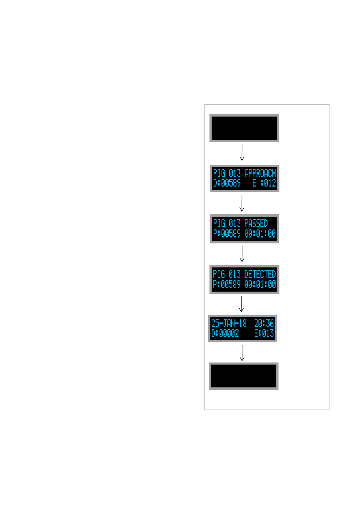
4.4. DETECTION MODE ............................................................................................. 9
4.4.1. PIG PASSED .................................................................................................. 9
4.4.2. PIG DETECTION ONLY .................................................................................... 9
4.4.3. DETECTION DELAY....................................................................................... 10
4.5. SINGLE BUTTON MENU INTERFACE.................................................................... 11
4.5.1. VIEW EVENTS ............................................................................................. 13
4.5.2. COPY EVENTS TO SD CARD........................................................................... 13
4.5.3. DELETE ALL EVENTS .................................................................................... 13
4.5.4. SHUTDOWN ................................................................................................ 13
4.5.5. DATE.......................................................................................................... 14
4.5.6. TIME .......................................................................................................... 14
4.5.7. THRESHOLD................................................................................................ 14
4.5.8. POWER MODE ............................................................................................. 14
4.5.9. STABILISATION DELAY ................................................................................. 14
4.5.10. DETECTION DELAY....................................................................................... 14
4.5.11. DETECTION METHOD ................................................................................... 14
4.5.12. AUTO POWER OFF........................................................................................ 15
4.5.13. RELAY LOGIC .............................................................................................. 15
4.5.14. SENSOR SELECT.......................................................................................... 15
4.5.15. SENSOR OUTPUT ......................................................................................... 15
4.5.16. LED FLASH.................................................................................................. 15
4.5.17. BLUETOOTH ................................................................................................ 16
4.5.18. INTERFACE ................................................................................................. 16
4.5.19. RS485 BAUD RATE....................................................................................... 16
4.5.20. RS485 PARITY ............................................................................................. 16
4.5.21. MODBUS ADDRESS ...................................................................................... 16
4.5.22. SD LOG ...................................................................................................... 16
4.5.23. LANGUAGE.................................................................................................. 16
4.5.24. RESET TO FACTORY SETTINGS ...................................................................... 16
4.5.25. EXIT MENU ................................................................................................. 17
4.6. MODBUS RTU RS485 INTERFACE ....................................................................... 17
4.6.1. MODBUS REGISTER MAP .............................................................................. 17
4.7. EVENT LOGGING AND SD CARD ........................................................................ 20
4.7.1. EVENT LOGGING ......................................................................................... 20
4.7.2. SD CARD .................................................................................................... 20
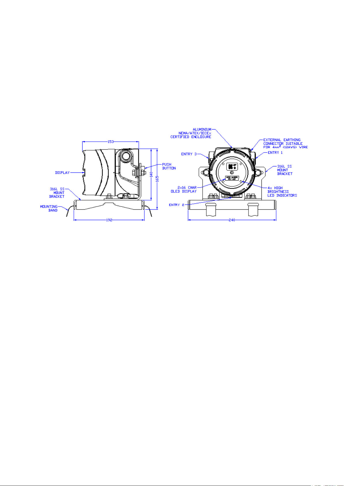
4.8. MOUNTING ..................................................................................................... 21
4.8.1. REMOTE SENSOR MOUNTING ........................................................................ 21
4.9. BATTERY REPLACEMENT ................................................................................... 22
4.10. EXTERNAL CONNECTIONS ................................................................................ 23
4.10.1. RELAY OUTPUT ............................................................................................ 24
4.10.2. CURRENT LOOP OUTPUT ............................................................................... 24
4.11. INTERNAL HEATER........................................................................................... 24
4.12. RTC BACKUP ................................................................................................... 25
4.13. LoRa .............................................................................................................. 26
4.14. RECOMMENDED MAGNET ARRANGEMENT ........................................................... 28
5. BLUETOOTH INTEGRATION ................................................................................... 29

4003_5001_D02 Page 3 of 35
5.1. BLUETOOTH ENABLE ........................................................................................ 29
5.2. BLUETOOTH CONNECTION................................................................................ 29
5.3. DEVICE DISPLAY INFORMATION ........................................................................ 31
5.3.1. DEVICE CHANGEABLE FIELDS ....................................................................... 31
5.3.2. INDICATION ONLY ....................................................................................... 31
5.3.3. LOGGED DATA ............................................................................................ 31
6. ROUTINE MAINTENANCE AND STORAGE................................................................. 32
7. DISPOSAL........................................................................................................... 32
8. WARRANTY ......................................................................................................... 32
9. SAFETY INSTRUCTIONS........................................................................................ 33

4003_5001_D02 Page 4 of 35
1. GENERAL DESCRIPTION
The OnlinE 4003 MAGSIG® is a robust, non-intrusive magnetic pig signaller which detects,
signals, and logs the passage of magnetic pigs at critical points along a pipeline both on land
and offshore. Events are signalled as they occur via an OLED dot matrix display and high
brightness LEDs positioned around the perimeter of the display.
The unit logs the time and date of up to 100 events. Logged events can be viewed locally on the
dot matrix display, transmitted remotely over several optional interfaces, or downloaded using
a laptop or onto a SD card. The unit can also continuously log sensor data to SD card. The user
can turn the unit ON and OFF as well as modify several settings using the single control button
and intuitive menu system.
The unit can be quickly and easily attached to a pipeline using ratchet straps or steel banding.
The unit is suitable for use on pipeline diameters up to 60” with wall thickness up to, and in
excess, of 40mm (please contact Online Electronics Ltd when wall thickness exceeds 25mm).
Detection speed ranges from 0.01 to 20 metres per second. Window of detection is typically
0.5m either side of the unit. The detection capabilities vary depending on the background
magnetic noise, pig speed, pipeline diameter, wall thickness and the quality of magnets fitted.
For optimum performance it is recommended that pigs are fitted with magnets as described in
section 4.14 RECOMMENDED MAGNET ARRANGEMENT.
POWER OPTIONS: The unit can be powered from internal batteries or from an external +24Vdc
supply. Batteries can be fitted to provide backup power should the external supply fail. The unit
uses either 4 off individual ‘D’ sized cells which can either all be Alkaline (DURACELL ID1300)
OR NiMH (Annsman Max E –ATEX/IECEx only). The 4003 also caters for 2 off Lithium (SAFT
LS33600) cells, this option being configured at manufacture.
ENTRY OPTIONS: The standard unit comes with 2 off ¾” NPT entries with blanking elements
installed. There is room inside the unit to make electrical connections without the need for
additional junction boxes or enclosures. Certified adaptors are generally available for other
thread types.
REMOTE SENSOR OPTION: The 4003 sensor is available in its own metal housing and is
connected to the main unit via solid or flexible conduit. A junction box provides 2 entries for
external electrical and signal connections.
MATERIAL OPTIONS: The unit can be supplied with an epoxy coated Aluminium Alloy 6082-
T6 or uncoated 316L Stainless Steel housing. Alternative coatings can be catered for.
TEMPERATURE RANGE OPTIONS: Ambient temperatures of -50°C can be accommodated by
installing a heater within the electronics housing. Higher pipeline surface temperatures can be
accommodated using a thermally insulated remote sensor.

4003_5001_D02 Page 5 of 35
2. SPECIFICATIONS
2.1. GENERAL
External supply ....................................................................+21.6Vdc to +26.4Vdc, <1.0W
Loop powered current loop ................................................................................... 8- 20mA
Temperature range using external supply (NO CELLS FITTED) -50°C to +85°C (-58 to +185°F)
Battery type ..................................................................4x DURACELL ID1300 Alkaline cells
Battery type ........................................................................ 2x SAFT LS33600 Lithium cells
Battery life in Listening/Low Power Mode at +20°C ..................................up to 400 Days Note 1
Temperature range while cells installed ...................Refer to Section 9 SAFETY INSTRUCTIONS
Ingress Protection ..................................................................................... IP66 / NEMA 4X
ATEX/IECEx code ................................................ Refer to Section 9 SAFETY INSTRUCTIONS
EC Type Examination Certificate Number ................................................. SIRA18ATEX1244X
IECEx Certificate Number ............................................................................. SIR 18.0059X
CSA/CSA-US ....................................................................................... CSA18CA70166719
Weight in Aluminium....................................................................................... 3.5kg (8lbs)
Weight in Stainless Steel ............................................................................... 5.5kg (12lbs)
Note 1 In Listening/Low Power Mode at +20°C with Bluetooth & LED’s disabled. Dependent on initial battery capacity.
2.2. STANDARD OUTPUTS
DPDT Relay Output (Volt Free Contacts) ............................................................ 2A @ 30Vdc
ISA TYPE II 2 wire Current Loop Output ...............................................>18mA (DETECTION)
MODBUS ......................................................................................................RTU (RS485)
BLUETOOTH................................................................................................. Class 4 (BLE)
2.3. OPTION OUTPUTS
2.3.1. LORA RADIO MODEM
LoRa .............................................................. Radio frequency configured for country of use
External supply ....................................................................+21.6Vdc to +26.4Vdc, <5.0W
Battery type ........................................................................ 2x SAFT LS33600 Lithium cells

4003_5001_D02 Page 6 of 35
3. RULES FOR SAFE OPERATION
WARNING: The Special Conditions for Safe Use detailed in Section 9 SAFETY INSTRUCTIONS
of this manual must be observed at all times.
WARNING: The purchaser of this equipment is responsible for the training and competence
of operators and the manner in which it is used. This manual should be read through and
understood before installation and commissioning so that the operator is familiar with the
equipment. Contact Online Electronics Ltd immediately should any difficulty arise in the use of
this equipment.
CAUTION: If the unit is to be placed in storage, always ensure that it is turned OFF and the
batteries are removed and stored separately.

4003_5001_D02 Page 7 of 35
4. OPERATION
Familiarise yourself with the rules for safe operation of this equipment as described in Section 3
RULES FOR SAFE OPERATION.
The 4003 provides a 2x16 OLED dot matrix display at the front of the unit. A control button is
located on the rear of the unit. Push the control button firmly and evenly to operate.
4.1. TURNING ON
If external power is available, the unit will turn on
automatically when power is applied.
To turn the unit on when battery operated simply firmly
press and hold the control button until the COMPANY
LOGO appears on the display and then release, this
takes approximately 5 seconds.
The COMPANY LOGO will be displayed for 5 seconds
after power is applied or the button is released as shown
by the COUNTDOWN INDICATOR located at the lower
left corner of the display.
The COMPANY LOGO and subsequent start up screens
can be aborted by firmly pressing the CONTROL
BUTTON.
The next screen shows the PRODUCT LOGO and
firmware version.
The next screen shows the current date and time. If the
date and time has not been set or the RTC backup has
expired, an error message will be displayed to indicate
that the date and time require setting by the user.
The next screen shows the status of the AUTO POWER
OFF feature. See section 4.5.12 AUTO POWER OFF for
more information.
The next screen shows the detection method selected.
Reference section 4.5.11 DETECTION METHOD.
The unit now enters STABILISATION. During
STABILISATION the unit will not detect or log any
magnetic events and the LEDs will flash every 5
seconds. The remaining STABILISATION time is
displayed in HH:MM:SS format. When the
STABILISATION time reaches zero or the CONTROL
BUTTON is pressed, the unit will enter LISTENING
MODE. See section 4.2 STABILISATION for more
information.
While LISTENING, the screen will show the live
DIFFERENCE flux reading and the current number of
events logged along with the date and time of the most
recent event. The LEDs will flash every 5 seconds. See
section 4.3 LISTENING for more information.
COMPANY
LOGO
PRODUCT
LOGO
DATE & TIME
STABILISATION
LISTENING
PRESS/
TIMEOUT
PRESS/
TIMEOUT
PRESS/
TIMEOUT
PRESS/
TIMEOUT
APO STATUS
PRESS/
TIMEOUT
DETECTION
METHOD
PRESS/
TIMEOUT

4003_5001_D02 Page 8 of 35
4.2. STABILISATION
The STABILISATION delay occurs at switch ON only. During the STABILISATION delay the unit
will ignore all magnetic events. The LEDs will flash every 5 seconds and the relay and current
loop outputs will be in the DETECTION state. The STABILISATION delay can be used during
deployment to prevent any unwanted events from being logged due to movement of the unit in
the earths’ magnetic field and/or movement of nearby magnetic objects (such as vehicles).
The STABILISATION delay can be set to any value between 00:00:00 and 99:59:59 (in
HH:MM:SS format) using the CONTROL BUTTON or via the serial link. During the STABILISATION
delay a countdown timer is shown on the display, once this timer reaches 00:00:00 the unit will
start LISTENING. The STABILISATION delay can be bypassed by firmly pressing the CONTROL
BUTTON at any point during STABILISATION.
Remember that the STABILISATION delay occurs at switch ON only. If changes are made to the
STABILISATION delay setting then the unit should be turned OFF. The new STABILISATION delay
will occur whenever the unit is next turned ON.
4.3. LISTENING
Immediately after STABILISATION the unit will
display the LIVE DATA screen, similar to the screens
shown opposite.
If 0 events have occurred, this screen will show
E:00 with no date or time.
Once an event has occurred, this screen will show
the most recent EVENT number and the date and
time the event occurred. The example shown is
EVENT #12 which occurred on 01/21/18 at 13:43
(in MM/DD/YY HH:MM format).
The live DIFFERENCE flux reading D:0002 is also
displayed. In a magnetically quiet environment this
number can be expected to flicker between 0000
and 0005. After displaying the LIVE DATA screen for
10 seconds the display will be switched off as shown
opposite.
While LISTENING the LEDs around the display will flash every 5 seconds, if enabled, and the
relay and current loop outputs will be in the LISTENING state. The unit continually takes RAW
flux readings which are FILTERED and the DIFFERENCE between the RAW and FILTERED values
calculated. If the DIFFERENCE exceeds the THRESHOLD setting, then the unit will enter
DETECTION MODE where an event will be signalled if the detection criteria is met. The following
events may interrupt the unit while in listening mode:
MAGNETIC EVENT –If a DIFFERENCE flux reading greater than the THRESHOLD value is
detected while the unit is LISTENING, the unit will enter DETECTION MODE once the detection
criteria has been met an EVENT will be signalled (discussed in section 4.4 DETECTION MODE).
CONTROL BUTTON –Firmly pressing and holding the CONTROL BUTTON momentarily (< 1
second) will enable the LIVE DATA screen for 10 seconds. Firmly pressing and holding the
CONTROL BUTTON for > 3 seconds will enter the MENU interface which is described in section
4.5 SINGLE BUTTON MENU INTERFACE of this manual.
SERIAL COMMAND –If a serial command is received via the serial data link then it will be
processed before the unit continues LISTENING.
LISTENING
0 EVENTS
LISTENING
12 EVENTS
LISTENING
DISPLAY OFF
OR
10 SEC
TIMEOUT

4003_5001_D02 Page 9 of 35
4.4. DETECTION MODE
There are two DETECTION METHODS. The default PIG PASS mode detects when the PIG has
likely to have PASSED the signaller and DETECTION ONLY detects the presence of a pig but not
necessarily that it has passed. The latter is useful when trying to determine when a PIG has
been launched, where the pig is initially present, and the pig’s movement will be away from the
signaller –i.e. will not create a flux peak.
4.4.1. PIG PASSED
Once the gauss reading crosses the threshold,
DETECTION starts, the pig state changes to PIG
APPROACH and the pig approach screen is shown. The
GAUSS reading shows the live gauss reading.
PIG PASSED is signalled when the flux reading has
peaked and fallen by a defined drop as specified by
the DETECTION CRITERIA, reference section 4.5.11
DETECTION METHOD. The larger the defined drop,
the more likely that the pig has passed the unit.
However, if the signaller is located close to the pig
receiver, then a smaller drop should be considered as
the pig’s magnetic signal may not fully clear the
signaller.
During DETECTION the display shows PIG nnn
PASSED and the LEDs around the display will flash
every 1 second and the relay and current loop outputs
will be in the DETECTION state, the unit will keep
logging until its internal buffer is full (or the CONTROL
BUTTON is firmly pressed), the event will then be
logged.
If DETECTION starts and the pig does not pass the
signaller, the signaller will timeout after 3 minutes
and 20 seconds the signaller and will return to
LISTENING (no DETECTION delay), the data will be
logged but no event will be signalled. In this situation,
the pig has been detected but is likely to have stopped
before the signaller. If the pig then moves and passes
the signaller (providing the gauss value exceed the
THRESHOLD was far enough away to cause a peak –
otherwise the signaller will timeout again and log the
data), a PIG PASSED event is likely to be triggered If
the unit is in LP MODE, the screen will stay on until
DETECTION completes or the unit times out and
reverts to LISTENING where normal LP mode will
resume.
4.4.2. PIG DETECTION ONLY
Once the gauss reading crosses the threshold, DETECTION starts, the pig state changes to PIG
APPROACH and the pig approach screen is shown. The gauss reading shows the live gauss
reading.
THRESHOLD
EXCEEDED
PIG DETECTION
DETECTED ONLY
PRESS/
TIMEOUT
LISTENING
DISPLAY OFF
LISTENING
13 EVENTS
LISTENING
DISPLAY OFF
(LP MODE)
10 SEC
TIMEOUT
EVENT
TRIGGERED
OR
PIG APPROACH
PIG DETECTION
PASSED

4003_5001_D02 Page 10 of 35
DETECTION event is signalled when the flux reading has peaked and the buffer (at current fill
rate) is filled.
During DETECTION display shows PIG nnn DETECTED and the LEDs around the display will flash
every 1 second and the relay and current loop outputs will be in the DETECTION state.
The unit will remain in this state for the length of time defined by the DETECTION delay. A
countdown timer representing the DETECTION delay will be shown at the bottom of the screen
along with the peak gauss recorded. When the DETECTION delay reaches 00:00:00 the unit will
return to LISTENING.
If DETECTION starts and there is no peak (i.e. pig inches closer but does not stop or pass) within
3 minute and 20 seconds the signaller will signal the pig DETECTION. If after the DETECTION
period completes, the pig is still close and still moving (or moves away) such that the
THRESHOLD is again crossed, a second DETECTION will occur.
4.4.3. DETECTION DELAY
The DETECTION delay controls how long the unit will signal an event for. Usually it will be
configured to give the magnetic pig enough time to get out of range of the sensor after it has
been detected to avoid re-trigger. When dealing with pig trains, the expected pig speed and
separation should be used to configure a suitable value for the DETECTION delay such that the
unit will not detect the same pig twice but will enter LISTENING mode in time to detect the next
pig.
The unit can log up to 100 events with date, time,
and the peak DIFFERENCE flux reading. Once 100
events have been logged the screen opposite will be
displayed, indicating that the logger memory is full.
Subsequent events will be signalled but no data will
be logged. If an SD card is installed and Logging is
disabled, the EVENTs will continue to be logged to
the SD card if the EEPROM is full.
The DETECTION delay can be set to any value between 00:00:00 and 98:59:59 (in HH:MM:SS
format) using the CONTROL BUTTON or via the serial link. There are 2x special values which can
be used:
DEBUG MODE –If the DETECTION delay is set to 00:00:00 then the unit works in DEBUG mode.
If a reading greater than the THRESHOLD value is detected in DEBUG mode then the LEDs will
flash every second to indicate that the THRESHOLD has been crossed, but no EVENT will be
logged, and the unit will not start a DETECTION delay. This can be very useful for determining
the magnetic signature of a pig when used in combination with the CONFIGURATION SOFTWARE.
LATCHED DETECTION –If the DETECTION delay HH (hours) field is set to 99 then when an
EVENT occurs the unit will LATCH in DETECTION MODE showing the EVENT information and
flashing the LEDs every second. To begin LISTENING again the CONTROL BUTTON must be firmly
pressed or by resetting PIG DETECTION Modbus coil (Modbus address 10000). The EVENT data
will be logged once the event buffer has been filled.
EVENT
MEMORY FULL

4003_5001_D02 Page 11 of 35
4.5. SINGLE BUTTON MENU INTERFACE
While LISTENING, the control button can be firmly pressed for > 2 seconds to enter the menu
interface. While in the menu interface, the unit will ignore all magnetic disturbances including
PIG passages. From the menu the user can configure several parameters which are discussed in
this section.
The menu interface is navigated using the control button. A firm momentary
button press (< 2 second) cycles through the menu items and a long button
press (> 3 seconds) selects the current menu item. If the control button is not
pressed for 30 seconds, or if the user selects the EXIT MENU option the unit will
return to LISTENING mode.
LISTENING - BLANK SCREEN
LIVE DATA SCREEN
LONG CONTROL
BUTTON PRESS
> 3 SECONDS
SHORT CONTROL
BUTTON PRESS
< 1 SECOND

4003_5001_D02 Page 12 of 35
When an editable menu item has been
selected a ‘>’ will appear in the bottom
left corner of the display to indicate that
the selected menu item is now in edit
mode and the button may be released.
The cursor will blink to indicate the field
currently being edited.
In edit mode a momentary button press
(< 1 second) cycles through the possible
options. (See POWER MODE example)
For menu options such as date and time
where there are numeric fields to edit,
press and hold to advance the cursor to
the next digit. Once the last digit has been
reached the cursor will loop back to the
first. (See MODBUS ADDRESS example)
Once the value has been configured as
required a long button press (> 3
seconds) is required to save the new
value to memory. Once the button has
been pressed long enough to save the
value a ‘*’ will be displayed in the bottom
left corner of the screen to indicate that
the button may now be released. The
display will now return to the main menu.
When a menu item that performs an
action such as view events is selected a
‘*’ will be displayed in the bottom left
corner of the display to indicate that the
item has been selected and the desired
action will be performed once the button
has been released.
Should a menu item be selected for
editing inadvertently then in order to
prevent making an undesired change, do
not press the button for ~30 seconds.
This will cause the menu system to time
out and the item value will not have been
modified.
LONG PRESS TO
ENTER EDIT MODE
MOMENTARY PRESS
TOGGLES OPTIONS
LONG PRESS TO
SAVE
LONG PRESS TO
SAVE
MOMENTARY PRESS
INCREMENTS DIGIT
PRESS & HOLD TO
ADVANCE CURSOR
PRESS & HOLD TO
ADVANCE CURSOR
LONG PRESS TO
ENTER EDIT MODE

4003_5001_D02 Page 13 of 35
4.5.1. VIEW EVENTS
Selecting this item will allow the user to cycle through all logged EVENTS from newest to oldest.
The peak DIFFERENCE flux reading, EVENT number, and EVENT date and time are shown. Firmly
pressing the CONTROL BUTTON momentarily will cycle to the next event. If the control button
is not pressed for 30 seconds, or if the user cycles beyond the last recorded event the unit will
return to LISTENING mode.
4.5.2. COPY EVENTS TO SD CARD
Selecting this item will copy ALL events (including erased events)
to the SD card if present. If the SD card is not present, an “SD
CARD NOT INSTALLED” error will be displayed. If the EVENT
memory has not been previously written an “EVENT XXX SKIPPED”
will be displayed. For each event successfully written to SD card
as “EVENT XXX SUCCESSFUL” will be shown. If the event already
exists on the SD card; with same detection time/date, it will be
overwritten. The process can be stopped by firmly pressing the
CONTROL BUTTON.
Each event written will be in Comma Separated Values (.csv)
format which can be read by most spreadsheet applications. The
filename format of “YYMMDD HHMMSS EVENT XXX LOG.csv”,
where YYMMDD is the date, HHMMSS is the time and XXX is the
event number.
Each log file will consist of
Event No: XXX
Threshold Time: DD/MM/YY HH:MM:SS
Detection Time: DD/MM/YY HH:MM:SS
Peak Difference: 3699mG
Peak Raw 4216mG
Filter: 0517mG
Log interval 0.1 Seconds
Detection index 125
Status: 0
Event Data
XXXX, XXXX … … XXXX
End of Event Data
The log interval is the time span between each data value.
Detection index is the index of the data value where the detection criteria was met.
4.5.3. DELETE ALL EVENTS
Selecting this item will delete all logged EVENT data. A screen will be displayed saying “PRESS
TO ERASE ALL EVENTS”. To erase all events, firmly press the CONTROL BUTTON before the
COUNTDOWN INDICATOR reaches 0. To cancel the erase simply allow the COUNTDOWN
INDICATOR to reach 0 without pressing the CONTROL BUTTON.
4.5.4. SHUTDOWN
Selecting this item switches off the unit. The unit will remember all settings (such as the DELAYS
and THRESHOLD) until next time the unit is switched on.

4003_5001_D02 Page 14 of 35
4.5.5. DATE
Selecting this item allows the date to be adjusted. Ensure that a valid date is entered in
DD/MMM/YY format. Refer to Section 4.12 RTC BACKUP.
4.5.6. TIME
Selecting this item allows the time to be adjusted. Ensure that a valid time is entered in 24hour,
HH:MM format. Refer to Section 4.12 RTC BACKUP.
4.5.7. THRESHOLD
CAUTION: Adjusting this parameter without first consulting Online Electronics Ltd may cause
the unit to miss pig passages or give false detections.
Selecting this item allows the THRESHOLD level to be configured to control the sensitivity of the
unit. The standard THRESHOLD value is 35mG. Reducing the THRESHOLD value increases the
sensitivity. The THRESHOLD can be configured to any value between 5mG and 9999mG.
4.5.8. POWER MODE
Selecting this item allows the power mode to be configured. In STANDARD POWER MODE the
display will be ON all of the time. The display draws significant power from the batteries which
will reduce the battery life of the unit. In LOW POWER MODE the display will turn OFF after 10
seconds to preserve the battery life. The detection routines are identical in each mode.
4.5.9. STABILISATION DELAY
Selecting this item allows the STABILISATION delay to be configured. It is possible to configure
any value between 00:00:00 and 99:59:59 in HH:MM:SS format. Refer to Section 4.2
STABILISATION for further information on the STABILISATION delay functionality.
4.5.10. DETECTION DELAY
Selecting this item allows the DETECTION delay to be configured. It is possible to configure any
value between 00:00:00 and 99:59:59 in HH:MM:SS format. See section 4.4 DETECTION MODE
for further information on the DETECTION delay functionality.
4.5.11. DETECTION METHOD
Selecting this item allows the detection method to be configured. The options available are:
PEAK –50%
PEAK –25%
PEAK –10%
PEAK –05%
DETECTION ONLY
PEAK –xx% determine the PIG PASSED detection criteria, reference 4.4.1 PIG PASSED, and the
DETECTION ONLY selects the pig detection only detection criteria, reference section 4.4.2 PIG
DETECTION ONLY.

4003_5001_D02 Page 15 of 35
4.5.12. AUTO POWER OFF
Selecting this item allows the AUTO POWER OFF function to be configured. It is possible to
configure any number of days from 01 to 28.
The AUTO POWER OFF timer will be ENABLED immediately once any non-zero value is set.
While ENABLED, each time the unit is powered ON the AUTO POWER OFF timer will restart and
the unit will automatically shut down after the configured number of days has elapsed.
To DISABLE the AUTO POWER OFF feature the number of days must be set to 00.
The AUTO POWER OFF feature will only operate when the unit is being powered from the internal
batteries. If the unit has an active external power connection, then it will be automatically
powered on at all times and this feature should be disabled.
4.5.13. RELAY LOGIC
Selecting this item allows the RELAY LOGIC to be configured.
If RELAY LOGIC is configured as NORMAL then while in the LISTENING state, the Normally Closed
contacts of the relays will be connected to their respective Common contacts and the Normally
Open contacts will be open. While in the DETECTION state, the Normally Closed contacts of the
relays will be open and the Normally Open contacts will be connected to their respective Common
contacts.
If RELAY LOGIC is configured as INVERTED then then while in the LISTENING state, the Normally
Closed contacts of the relays will be open and the Normally Open contacts will be connected to
their respective Common contacts. While in the DETECTION state, the Normally Closed contacts
of the relays will be connected to their respective Common contacts and the Normally Open
contacts will be open.
4.5.14. SENSOR SELECT
Selecting this item allows the active magnetic sensor to be selected.
If LOCAL is selected, then the INTERNAL magnetic sensor will be active.
If REMOTE is selected, then the REMOTE magnetic sensor will be active.
4.5.15. SENSOR OUTPUT
Selecting this item allows the user to configure which components of the magnetic field are used
by the unit to detect pig passages. There are currently four possible selections.
VECTOR XYZ –Full 3D magnetic field strength will be used.
X-AXIS –Only the x component will be used.
Y-AXIS –Only the y component will be used.
Z-AXIS –Only the z component will be used.
4.5.16. LED FLASH
Selecting this item allows the HIGH BRIGHTNESS LED INDICATORS fitted to the front of unit to
be ENABLED or DISABLED.

4003_5001_D02 Page 16 of 35
4.5.17. BLUETOOTH
Selecting this item allows the Bluetooth module to be ENABLED or DISABLED. The Bluetooth
module should be disabled when not required as the module draws significant power from the
batteries which will reduce the battery life of the unit. Refer to Section 5 BLUETOOTH
INTEGRATION
4.5.18. INTERFACE
Selecting this item configures the interface type. Either MODBUS, using the RS485 interface, or
CURRENT LOOP signaling. When current loop is enabled pig passage is signaled by drawing more
current on the power supply/current loop connection.
4.5.19. RS485 BAUD RATE
Selecting this item configures the BAUD rate for the serial interface. Either 19200 BAUD (required
by MODBUS protocol) or 9600 BAUD can be selected. The word size is fixed at 8 bits with one
stop bit. In total 11 bits are transmitted per character, START + 8 BIT DATA + PARITY + STOP
BIT.
4.5.20. RS485 PARITY
Selecting this item configures the type parity check for the serial interface. Either EVEN PARITY
(required by MODBUS protocol) or NO PARITY can be selected. In total 11 bits are transmitted
per character, START + 8 BIT DATA + PARITY + STOP BIT.
4.5.21. MODBUS ADDRESS
Selecting this item configures the MODBUS slave address for the unit. Valid addresses are from
1 to 247.
4.5.22. SD LOG
Selecting this item allows the SD Logging feature to be ENABLED or DISABLED. This feature can
be used to log magnetic flux readings from the sensor to an SD card (if fitted). Timestamped
data is logged every 200mS using the Comma Separated Value format (.csv). Logging (when
enabled) occurs while the signaller is powered and an SD card is fitted.
Data is recorded at approximately 3.5 seconds per KB.
A 16GB SD card should have enough capacity to log data for approximately 1.5 years,
reference 4.7 EVENT LOGGING AND SD .
4.5.23. LANGUAGE
Selecting this item allows the menu interface language to be selected.
4.5.24. RESET TO FACTORY SETTINGS
Selecting this item will restore the unit settings back to factory defaults. Performing this action
will also delete all stored events.

4003_5001_D02 Page 17 of 35
4.5.25. EXIT MENU
Selecting this item will EXIT the menu interface and the unit will resume LISTENING.
4.6. MODBUS RTU RS485 INTERFACE
Communication to the 4003, via the RS485 interface, makes use of MODBUS protocol as defined
in MODBUS OVER SERIAL LINE V1.02 published by the MODBUS organisation. The
communication parameters adhere to this standard using the default RTU transmission mode.
Communication parameters can be set up via the Menu System, Bluetooth application or
MODBUS itself. All the parameters in the 4003 can be accessed via the MODBUS interface.
MODBUS is also used over Bluetooth via a VCP connection which requires additional software.
The 4003 implements an exclusive block structure where each type of block has its own unique
addresses. The base address for each type will remain constant although the content and number
of each type of registers maybe updated but a table will exist in the manual detailing the register
map applicable to the version of software for the 4003.
TYPE
START
ADDRESS
FUNCTION CODES
COILS
10000
1,5
HOLDING REGISTERS
40000
3,6,16
INPUT REGISTERS
30000
4
The 4003 contains two processing units. The Main Processor performs the majority of the
operational functions of the unit. The Communications Processor handles current loop signalling
and MODBUS communications. The two units are electrically isolated from each other so that
the communication interface can be isolated from the housing earth connection. The electrical
ground connection for the Main Processor is connected to the housing earth due to the use of
Zener Barrier type circuits inside the 4003 as required by hazardous area certification.
When MODBUS registers are updated the new values need to be transferred from the
Communications Processor to the Main Processor so there is a slight delay to enable this to be
performed. The Communications Processor keeps a copy of all registers which are updated by
the Main Processor. Again, there may be a slight delay in this update.
4.6.1. MODBUS REGISTER MAP
Care should be taken when remotely controlling/configuring the 4003 via the MODBUS interface
as values set intentionally, or unintentionally, will immediately affect the operation of the 4003.
E.g. enabling relay inversion although a useful test will cause the relays to changeover and signal
an indicate an event when no event is active.
In general:
Setting a coil activates the function detailed.
Reading a coil, whose contents are set, indicates STATUS active.
COILS
REGISTER
STATUS/FUNCTION
DESCRIPTION
10000
Pig Detected Indication
Reference section 4.4
10001
Delete All Events
Reference section 4.5.3
10002
Enable Low Power Mode
Low power enabled when set
10003
Invert Relay Polarity
Refer to Section 4.5.13

4003_5001_D02 Page 18 of 35
RELAY LOGIC
10004
Enable Remote Sensor
Remote sensor selected when set
10005
Enable SD Card Logging
10006
Enable LED Flash
Refer to Section 4.5.16 LED FLASH
10007
Enable Bluetooth
10010
Pig Approach Indication
Reference section 4.4
HOLDING REGISTERS
40000
Language
Refer to Section 4.5.23 LANGUAGE
40001
APO Days
Refer to Section 4.5.12 AUTO POWER OFF
40002
Stabilisation HH
Refer to Section 4.5.9 STABILISATION DELAY
40003
Stabilisation Delay MM
40004
Stabilisation Delay SS
40005
Detect Delay HH
Refer to Section 4.5.10 DETECTION DELAY
40006
Detect Delay MM
40007
Detect Delay SS
40008
System Date DD
Current day
40009
System Date MM
Current month
40010
System Date YY
Current year
40011
System Time HH
Current hour
40012
System Time MM
Current minute
40013
Event Requested
Event number to view over MODBUS
40014
MODBUS Slave Address
MODBUS slave address
40015
RS485 Baud Rate
0 = 9600 BAUD, 1 = 19200 BAUD
40016
RS485 Parity
0 = EVEN parity, 1 = NO PARITY
40017
Threshold
Refer to Section 4.5.7 THRESHOLD
INPUT REGISTERS
30000
Serial Number
Serial number of unit
30001
DOMyy
Year of manufacture
30002
DOMmm
Month of manufacture
30003
FWRevMajor
Software Revision Number
30004
FWRevMinor
Software Revision Number
30005
Number of events
Current number of events
30006
Event Date DD
Selected event date day
30007
Event Date MM
Selected event date month
30008
Event Date YY
Selected event date year
30009
Event Time HH
Selected event time hour
30010
Event Time MM
Selected event time minute
30011
Event Peak Value
Selected event peak magnetic flux
30012
Difference
Current relative flux
30013
Magnitude
Current flux magnitude
30014
xAxis
Current flux magnitude +8000mG offset in x direction
30015
yAxis
Current flux magnitude +8000mG offset in y direction
30016
zAxis
Current flux magnitude +8000mG offset in z direction
30017
Battery Voltage
Current battery voltage if fitted
30018
Event Threshold Crossed
HH
Current Event, Time the threshold was crossed
30019
Event Threshold Crossed
MM
Current Event, Time the threshold was crossed
30020
Event Threshold Crossed
SS
Current Event, Time the threshold was crossed
30021
Event Filter Value
Background filter value at time of Event Trigger
30022
Event Time SS
Selected event time Second
Table of contents