ONNLINE 920 User manual

PROFESSIONAL
Side 1Norwegian
TRMS IP67 Digital multimeter | 920
PROFESSIONAL
English
Finnish
Norwegian
Swedish
920
10
20
30
40
50
60
0
TRUE RMS IP67 MULTIMETER
V
V
V
mA
A

Side 2 English
Introduction
This meter measures AC/DC Voltage, AC/DC Current, Resistance,
Capacitance, Frequency (electrical & electronic), Diode Test, and
Continuity plus Thermocouple Temperature. Proper use and care of this
meter will provide many years of reliable service.
Safety
This symbol adjacent to another symbol, terminal or operating
device indicates that the operator must refer to an explanation in
the Operating Instructions to avoid personal injury or damage to
the meter.
This WARNING symbol indicates a potentially hazardous situation,
which if not avoided, could result in death or serious injury.
This CAUTION symbol indicates a potentially hazardous situation,
which if not avoided, may result damage to the product.
This symbol advises the user that the terminal(s) so marked
must not be connected to a circuit point at which the voltage with
respect to earth ground exceeds (in this case) 1000 VAC or VDC.
This symbol adjacent to one or more terminals identifies them
as being associated with ranges that may, in normal use, be
subjected to particularly hazardous voltages. For maximum safety,
the meter and its test leads should not be handled when these
terminals are energized.
This symbol indicates that a device is protected throughout by
double insulation or reinforced insulation.
WARNING
CAUTION
MAX
1000V

PROFESSIONAL
Side 3English
PER IEC1010 OVERVOLTAGE INSTALLATION CATEGORY
OVERVOLTAGE CATEGORY I
Equipment of OVERVOLTAGE CATEGORY I is equipment for connection to
circuits in which measures are taken to limit the transient overvoltages to
an appropriate low level.
Note – Examples include protected electronic circuits.
OVERVOLTAGE CATEGORY II
Equipment of OVERVOLTAGE CATEGORY II is energy-consuming equipment
to be supplied from the fixed installation.
Note – Examples include household, office, and laboratory appliances.
OVERVOLTAGE CATEGORY III
Equipment of OVERVOLTAGE CATEGORY III is equipment in fixed
installations.
Note – Examples include switches in the fixed installation and some
equipment for industrial use with permanent connection to the fixed
installation.
OVERVOLTAGE CATEGORY IV
Equipment of OVERVOLTAGE CATEGORY IV is for use at the origin of the
installation.
Note – Examples include electricity meters and primary over-current
protection equipment

Side 4 English
SAFETY INSTRUCTIONS
This meter has been designed for safe use, but must be operated with
caution. The rules listed below must be carefully followed for safe
operation.
1. NEVER apply voltage or current to the meter that exceeds the specified
maximum:
Input Protection Limits
Function Maximum Input
V DC or V AC 1000VDC/AC rms
mA AC/DC 800mA 1000V fast acting fuse
A AC/DC 10A 1000V fast acting fuse (20A for
30 seconds max every 15 minutes)
Frequency, Resistance,
Capacitance, Duty Cycle, Diode
Test, Continuity
1000VDC/AC rms
Temperature 1000VDC/AC rms
2. USE EXTREME CAUTION when working with high voltages.
3. DO NOT measure voltage if the voltage on the “COM” input jack exceeds
1000V above earth ground.
4. NEVER connect the meter leads across a voltage source while the
function switch is in the current, resistance, or diode mode. Doing so
can damage the meter.
5. ALWAYS discharge filter capacitors in power supplies and disconnect
the power when making resistance or diode tests.
6. ALWAYS turn off the power and disconnect the test leads before opening
the covers to replace the fuse or batteries.
7. NEVER operate the meter unless the back cover and the battery and
fuse covers are in place and fastened securely.
If the equipment is used in a manner not specified by the manufacturer,
the protection provided by the equipment may be impaired.

PROFESSIONAL
Side 5English
Controls and Jacks
1. 6,000 count LCD display
2. Hz% button
3. RANGE button
4. MODE button
5. Function switch
6. mA, µA and 10A input jacks
7. COM input jack
8. Positive input jack
9. Backlight and Hold button
10. MAX/MIN button
11. REL button
12. NCV indicate lamp
Note: Tilt stand and battery compartment are on rear of unit.
¦ ¸
mA
A
¦ ¸
V
V
V
1
4
P1
P2
P3
S1
S2
BP0 BP60
BP1

Side 6 English
Symbols and Annunciators
Continuity
Diode test
Battery status
nnano (10-9) (capacitance)
µmicro (10-6) (amps, cap)
mmilli (10-3) (volts, amps)
AAmps
kkilo (103) (ohms)
FFarads (capacitance)
Mmega (106) (ohms)
ΩOhms
Hz Hertz (frequency) VVolts
REL Relative
AC Alternating current AUTO Autoranging
DC Direct current HOLD Display hold
ºF Degrees Fahrenheit ºC Degrees Centigrade
MAX Maximum MIN Minimum
AUTO Auto Range
APO Auto OFF
Backlight
BP1 Bargraph
1
4
P1
P2
P3
S1
S2
BP0 BP60
BP1

PROFESSIONAL
Side 7English
Operating Instructions
1. ALWAYS turn the function switch to the OFF position when the meter is
not in use.
2. If “OL” appears in the display during a measurement, the value exceeds
the range you have selected. Change to a higher range.
DC VOLTAGE MEASUREMENTS
1. Set the function switch to the “DC” position.
2. Insert the black test lead banana plug into the negative
COM jack. Insert the red test lead banana plug into the
positive V jack.
3. Touch the black test probe tip to the negative side of the
circuit. Touch the red test probe tip to the positive side
of the circuit.
4. Read the voltage in the display.
AC VOLTAGE MEASUREMENTS
1. Set the function switch to “AC” position.
2. Insert the black test lead banana plug into the negative
COM jack. Insert red test lead banana plug into the positive
V jack.
3. Touch the black test probe tip to the neutral side of the
circuit. Touch the red test probe tip to the “hot” side of the
circuit.
4. Read the voltage in the display
WARNING: Risk of electrocution. High-voltage circuits, both AC and DC,
are very dangerous and should be measured with great care.
CAUTION: Do not measure DC voltages if a motor on the
circuit is being switched ON or OFF. Large voltage surges
may occur that can damage the meter.
CAUTION: Do not measure AC voltages if a motor on the
circuit is being switched ON or OFF. Large voltage surges
may occur that can damage the meter.
G~

Side 8 English
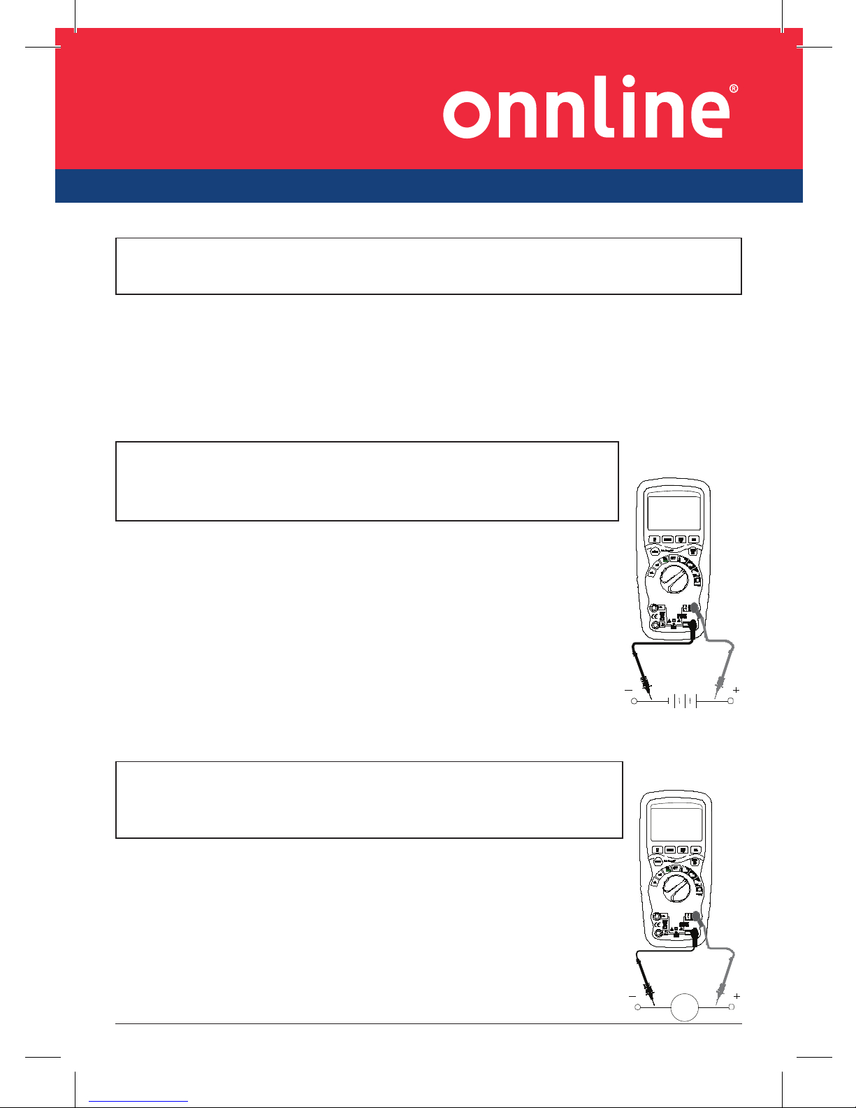
AC/DC CURRENT MEASUREMENTS
1. Insert the black test lead banana plug into the negative COM
jack.
2. For current measurements up to 6000µA AC/DC, set the
function switch to the µA position and insert the red test lead
banana plug into the µA/mA jack,press mode button to select
AC or DC.
3. For current measurements up to 600mA DC, set the function
switch to the mA position and insert the red test lead banana
plug into the µA/mA jack ,press mode button to select AC or
DC.
4. For current measurements up to 10A DC, set the function
switch to the 10A position and insert the red test lead banana
plug into the 10A jack, press mode button to select AC or DC.
5. Remove power from the circuit under test, then open up the
circuit at the point where you wish to measure current.
6. Touch the black test probe tip to the negative side of the circuit. Touch the red
test probe tip to the positive side of the circuit.
7. Apply power to the circuit and read the current in the display.
RESISTANCE MEASUREMENTS
1. Set the function switch to the Ω CAP position.
2. Insert the black test lead banana plug into the negative
COM jack. Insert the red test lead banana plug into the
positive Vjack.
3. Press the MODE button to indicate “Ω” on the display.
4. Touch the test probe tips across the circuit or part under test.
It is best to disconnect one side of the part under test so
the rest of the circuit will not interfere with the resistance
reading.
CAUTION: Do not make 10A current measurements for longer than 30
seconds. Exceeding 30 seconds may cause damage to the meter and/or the
test leads.
WARNING: To avoid electric shock, disconnect power to the
unit under test and discharge all capacitors before taking
any resistance measurements. Remove the batteries and
unplug the line cords.

PROFESSIONAL
Side 9English
CONTINUITY CHECK
1. Set the function switch to the Ω CAP
position.
2. Insert the black lead banana plug into the negative
COM jack. Insert the red test lead banana plug into
the positive Vjack.
3. Press the MODE button to indicate“ “ and “Ω” on
the display
4. Touch the test probe tips to the circuit or wire you
wish to check.
5. If the resistance is less than approximately 30Ω, the
audible signal will sound. If the circuit is open, the
display will indicate “OL”.
DIODE TEST
1. Set the function switch to the Ω CAP position.
2. Insert the black test lead banana plug into the negative COM jack and
the red test lead banana plug into the positive Vjack.
3. Press the MODE button to indicate“ “ and “V” on the display.
4. Touch the test probes to the diode under test.
Forward voltage will typically indicate 0.400 to
0.700V. Reverse voltage will indicate “OL”.
Shorted devices will indicate near 0V and an
open device will indicate “OL” in both
polarities.
WARNING: To avoid electric shock, never measure continuity on circuits
or wires that have voltage on them.

Side 10 English
CAPACITANCE MEASUREMENTS
1. Set the rotary function switch to the Ω CAP
position.
2. Insert the black test lead banana plug into the COM jack.
3. Insert the red test lead banana plug into the Vjack.
4. Touch the test leads to the capacitor to be tested. Read
the capacitance value in the display
TEMPERATURE MEASUREMENTS
1. Set the function switch to the “Temp” positive and press
the MODE key to select the “°C” measuring or “°F”
measuring.
2. Insert the Temperature Probe into the input jacks, making
sure to observe the correct polarity.
3. Touch the Temperature Probe head to the part
whose temperature you wish to measure. Keep the
probe touching the part under test until the reading
stabilizes (about 30 seconds).
4. Read the temperature in the display.
Note: The temperature probe is fitted with a type K
mini connector. A mini connector to banana connector
adaptor is supplied for connection to the input banana
jacks.
FREQUENCY MEASUREMENT
1. Set the function switch to the Hz/Duty position.
2. Insert the black test lead banana plug into the negative ( - ) jack (COM) and
the red test lead banana plug into the positive ( + ) jack (°F).
3. Touch the test probe tips to the circuit under test.
4. Read the frequency in the display. The digital reading will indicate the
proper decimal point, symbols (Hz, kHz, MHz ) and value.
NOTE: Press the MODE key to select the frequency or the duty cycle
measuring.
WARNING: To avoid electric shock, disconnect power to the unit under test
and discharge all capacitors before taking any capacitance measurements.
Remove the batteries and unplug the line cords.

PROFESSIONAL
Side 11English
NCV-contact AC Voltage Test (NCV)
1. Set the function switch to the ON position.
2. Remove the meter and face the NCV detector to ACV source.
3. If source votalge above 110V ,the NCV indicate lamp will light.
MODE BUTTON
1. To select DC/AC current or voltage or resistance/capacitance Diode/
Continuity or °C /°F or Hz/duty
2. Press the key then turn on the power , the Auto Power-off function
will be cancelled, the sign “APO” disappears in the LCD; and enters into
the sleep status (power-off), press the key then power on will have Auto
Power-off function.
DATA HOLD BUTTON
The Data Hold function allows the meter to “freeze” a measurement for
later reference.
1. Press the DATA HOLD button to “freeze” the reading on the indicator.
The indicator “HOLD” will be appear in the display.
2. Press the DATA HOLD button to return to normal operation.
3. Press the DATA HOLD button to last 2 second, the back light function is
enabled or disenabled.
RANGE BUTTON
When the meter is first turned on, it automatically goes into AutoRanging.
This automatically selects the best range for the measurements being
made and is generally the best mode for most measurements. For
measurement situations requiring that a range be manually selected,
perform the following:
1. Press the RANGE button. The “AUTO” display indicator will turn off.
2. Press the RANGE button to step through the available ranges until you
select the range you want.
3. Press and hold the RANGE button for 2 seconds to exit the Manual
Ranging mode and return to Auto Ranging.

Side 12 English
MAX/MIN BUTTON
The meter displays the maximum or minimum value of input in the Max/
Min mode. When Max/Min is pressed for the first time, the meter displays
the maximum value. The meter displays the minimum value when it is
pressed again. When Max/Min is pressed for the third time, the meter
displays current value. The meter returns to normal operation when Max/
Min is pressed and held for longer than one second. Press HOLD key
in Max/Min mode makes the meter stop updating the maximum or the
minimum value.
Low battery indication
When the icon appears alone in the display, the battery should be
replaced.
Maintenance
This MultiMeter is designed to provide years of dependable service, if the
following care instructions are performed:
1. KEEP THE METER DRY. If it gets wet, wipe it off.
2. USE AND STORE THE METER IN NORMAL TEMPERATURES.
Temperature extremes can shorten the life of the electronic parts and
distort or melt plastic parts.
3. HANDLE THE METER GENTLY AND CAREFULLY. Dropping it can damage
the electronic parts or the case.
4. KEEP THE METER CLEAN. Wipe the case occasionally with a damp cloth.
DO NOT use chemicals, cleaning solvents, or detergents.
5. USE ONLY FRESH BATTERIES OF THE RECOMMENDED SIZE AND TYPE.
Remove old or weak batteries so they do not leak and damage the unit.
6. IF THE METER IS TO BE STORED FOR A LONG PERIOD OF TIME, the
batteries should be removed to prevent damage to the unit.
WARNING: To avoid electric shock, disconnect the test leads from any
source of voltage before removing the back cover or the battery or fuse
covers.
WARNING: To avoid electric shock, do not operate your meter until the
battery and fuse covers are in place and fastened securely.

PROFESSIONAL
Side 13English
BATTERY INSTALLATION
1. Turn power off and disconnect the test leads from the meter.
2. Open the rear battery cover by removing two screws (B) using a Phillips
head screwdriver.
3. Insert the battery into battery holder, observing the correct polarity.
4. Put the battery cover back in place. Secure with the screws.
WARNING: To avoid electric shock, do not operate the meter until the
battery cover is in place and fastened securely.
NOTE: If your meter does not work properly, check the fuses and batteries
to make sure that they are still good and that they are properly inserted.
WARNING: To avoid electric shock, disconnect the test leads from any
source of voltage before removing the battery cover.

Side 14 English
Specifications
DC Voltage (Auto-ranging)
Range Resolution Accuracy
600.0mV 0.1mV
±0.1% of rdg ±2 digits
6.000V 1mV
60.00V 10mV
600.0V 100mV
1000V 1V ±0.3% of rdg ±2 digits
Input Impedance: 10MΩ.
Maximum Input: 1000V dc or 1000V ac rms.
AC Voltage (Auto-ranging)
Range Resolution Accuracy
6.000V 1mV
±0.8% of rdg ±4 digits60.00V 10mV
600.0V 100mV
1000V 1V ±1.2% of rdg ±4 digits
All AC voltage ranges are specified from 5% of range to 100% of range
Input Impedance: 10MΩ.
AC Response: 50 Hz to 400Hz
Maximum Input: 1000V dc or 1000V ac rms.
DC Current (Auto-ranging)
Range Resolution Accuracy
600.0uA 0.1uA
±0.8% of rdg ±3 digits6000uA 1uA
60.00mA 10uA
600.0mA 100uA ±1.2% of rdg ±3 digits
10A 10mA ±1.8% of rdg ±3 digits
Overload Protection: FF800mA / 1000V and F10A / 1000V Fuse.
Maximum Input: 6000uA dc on uA range
800mA dc on mA range
10A dc on 10A range.

PROFESSIONAL
Side 15English
AC Current (Auto-ranging)
Range Resolution Accuracy
600.0uA 0.1uA
±1.0% of rdg ±3 digits6000uA 1uA
60.00mA 10uA
600.0mA 100uA ±1.2% of rdg ±3 digits
10A 10mA ±2.0% of rdg ±3 digits
All AC Current ranges are specified from 5% of range to 100% of range
Overload Protection:FF800mA/1000V and F10A/1000V Fuse.
AC Response: 50 Hz to 400 Hz
Maximum Input: 6000uA ac rms on uA
800mA ac rms on mA
10A ac rms on 10A range.
Resistance [Ω] (Auto-ranging)
Range Resolution Accuracy
600.0Ω 0.1Ω ±0.5% of rdg ±4 digits
6.000kΩ 1Ω
±0.5% of rdg ±2 digits60.00kΩ 10Ω
600.0kΩ 100Ω
6.000MΩ 1kΩ ±1.5% of rdg ±8 digits
60.00MΩ 10kΩ
Input Protection: 1000V dc or 1000V ac rms.
Capacitance (Auto-ranging)
Range Resolution Accuracy
40.00nF 10pF ±5.0% of rdg ±20 digits
400.0nF 0.1nF
±3.0% of rdg ±5 digits
4.000uF 1nF
40.00uF 10nF
400.0uF 0.1uF
4000uF 1 uF ±5.0% of rdg ±10 digits
Input Protection: 1000V dc or 1000V ac rms.

Side 16 English
Frequency (Auto-ranging)
Range Resolution Accuracy
9.999Hz 0.001Hz
±1.2% of rdg ±3 digits
99.99 Hz 0.01Hz
999.9 Hz 0.1Hz
9.999KHz 1 Hz
99.99kHz 10Hz
999.9kHz 100Hz
9.999MHz 1kHz ±1.5% of rdg ±4 digits
Sensitivity: >0.5V RMS while ≤1MHz ;
Sensitivity: >3V RMS while >1MHz ;
Input Protection: 1000V dc or 1000V ac rms.
Duty Cycle
Range Resolution Accuracy
0.1%~99.9% 0.1% ±1.2% of rdg ±2 digits
Pulse width: >100us, <100ms;
Frequency width: 5Hz – 150kHz
Sensitivity: <0.5V RMS
Overload protection: 1000V dc or ac rms.
Temperature
Range Resolution Accuracy
-20°C ~+600°C 0.1 °C ± 3% of rdg ± 5 °C
600°C ~+1000°C 1 °C
-4 °F ~+600 °F 0.1°F ± 3% of rdg ± 8 °F
600°F ~+1832 °F 1°F
Sensor: Type K Thermocouple
Overload protection: 1000V dc or ac rms.

PROFESSIONAL
Side 17English
Diode Test
Range Resolution Accuracy
0.3mA typical 1 mV ±10% of rdg ±5 digits
Open circuit voltage: MAX. 2V dc
Overload protection: 1000V dc or ac rms.
Audible continuity
Audible threshold: Less than 30Ω Test current MAX. 0.3mA
Overload protection: 1000V dc or ac rms.
Enclosure Double molded, waterproof
Shock (Drop Test) 6.5 feet (2 meters)
Diode Test Test current of 0.9mA maximum, open circuit
voltage 2V DC typical
Continuity Check Audible signal will sound if the resistance is
less than 30Ω(approx.), test current <0.3mA
Temperature Sensor Requires type K thermocouple
Input Impedance >10MΩ VDC & >9MΩ VAC
AC Response True rms
AC True RMS: The term stands for “Root-Mean-Square,”
which represents the method of calculation
of the voltage or current value. Average
responding multimeters are calibrated to read
correctly only on sine waves and they will read
inaccurately on non-sine wave or distorted
signals. True rms meters read accurately on
either type of signal.
ACV Bandwidth 50Hz to 400Hz
Crest Factor ≤3 at full scale up to 500V, decreasing linearly
to ≤1.5 at 1000V
Display 60,00 count backlit liquid crystal with
bargraph
Overrange indication “OL” is displayed
Auto Power Off 15 minutes (approximately) with disable
feature

Side 18 English
Polarity Automatic (no indication for positive); Minus
(-) sign for negative
Measurement Rate 2 times per second, nominal
Low Battery Indication “ ” is displayed if battery voltage drops
below operating voltage
Battery One 9 volt (NEDA 1604) battery
Fuses mA, µA ranges; 0.8A/1000V ceramic fast blow
A range; 10A/1000V ceramic fast blow
Operating Temperature 41ºF to 104ºF (5ºC to 40ºC)
Storage Temperature -4°F to 140°F (-20°C to 60°C)
Operating Humidity Max 80% up to 87ºF (31ºC) decreasing linearly
to 50% at 104ºF (40ºC)
Storage Humidity <80%
Operating Altitude 7000ft. (2000meters) maximum.
Weight 0.753lb (342g) (includes holster).
Size 7.36” x 3.2” x 2.0” (187 x 81 x 50mm) (includes
holster)
Safety This meter is intended for origin of installation
use and protected, against the users, by
double insulation per EN61010-1 and
IEC61010-1 2nd Edition (2001) to Category IV
600V and Category III 1000V; Pollution Degree
2. The meter also meets UL 61010-1, 2nd
Edition (2004), CAN/CSA C22.2 No. 61010-1
2nd Edition (2004), and UL 61010B-2-031, 1st
Edition (2003).

PROFESSIONAL
Side 19Finnish
Johdanto
Tällä yleismittarilla voi testata AC/DC-jännitettä, AC/DC-virtaa,
resistanssia, kapasitanssia, frekvenssiä, diodeja, kontinuiteettia ja
lämpötilaa. Oikein käytettynä ja hoidettuna laite toimii luotettavasti vuosia.
Turvallisuus
Tämä symboli toisen symbolin, terminaalin tai käyttöyksikön
vieressä osoittaa, että käyttäjän on luettava selitys käyttöohjeesta
välttyäkseen henkilö- tai laitevahingolta.
Tämä varoitusmerkki osoittaa mahdollista vaaratilannetta, joka voi
johtaa vakavaan vammaan tai kuolemaan
Tämä varoitusmerkki osoittaa mahdollista vaaratilannetta, joka voi
aiheuttaa laitteen vaurioitumisen.
Tämä merkintä muistuttaa käyttäjää siitä, että merkitty/merkityt
terminaali/t eivät saa olla yhdistettyinä piiriin, jossa jännite
suhteessa maahan ylittää (tässä tapauksessa) 1000 VAC tai VDC.
Tällä merkinnällä yhden tai useiden terminaalien vieressä
tarkoitetaan alueita, jotka normaalikäytössä voivat altistua
erityisen vaarallisille jännitteille. Turvallisuuden takaamiseksi
laitetta ja testijohtoa ei saa käsitellä kun näissä terminaaleissa on
jännitettä.
Tämä merkintä kertoo, että laite on suojattu kaksinkertaisella tai
vahvistetulla eristyksellä.
VAROITUS
VARO
MAX
1000V

Side 20 Finnish
IEC1010-ylijänniteluokat:
YLIJÄNNITELUOKKA I
YLIJÄNNITELUOKKA I:een kuuluvat piireihin kytkettävät laitteet,
joissa ohimenevät ylijännitteet on rajoitettu sopivan matalalle tasolle.
Esimerkkeinä suojatut elektroniset piirit.
YLIJÄNNITELUOKKA II
YLIJÄNNITELUOKKA II:een kuuluvat energiaa kuluttavat, kiinteän
asennuksen laitteet. Esimerkkeinä kotitalous-, konttori- ja
laboratoriolaitteet.
YLIJÄNNITELUOKKA III
YLIJÄNNITELUOKKA III:een kuuluvat pysyvästi asennetut laitteet.
Esimerkkeinä kiinteiden asennusten katkaisijat sekä laitteet, jotka ovat
kiinni kiinteässä asennuksessa.
YLIJÄNNITELUOKKA IV
YLIJÄNNITELUOKKA IV:een kuuluvat laitteet on tarkoitettu sähkön
syöttöpisteisiin/jakeluun. Esimerkkeinä sähkömittarit ja sähköverkon
valvontalaitteet.
Table of contents
Languages: