Onstate
Technologies
PMSW27 Series
Occupancy PIR
Motion Sensor
Product Technical Information- Power Electronics
PMSW27 Series
Seei n with L E D L i ht i n
TM
Onstate Technolo ies BC, Canada Tel. 1-877-607-7811 On-tech@OnstateTech.com Pa e 3 of 4
Patent Pendin Specifications subject to chan e without notice. tech PMSW27 PIR occupancy sensor Rev1 09/11
Installation Instructions
AUTION
ELE TRI SHO K HAZARD.
USE PROPER SAFETY PRE AUTIONS.
Please carefully read throu h the installation instructions prior to installation.
NOTES:
1. Should be installed by qualified personnel.
2. Follow applicable local electrical codes.
3. DO NOT install near fans, HVAC air vents, or transient warm/cold objects or sources.
1. Determine mountin location on ceilin . The PIR
sensor can only sense direct li ht-of-si ht.
2. Shut off power source. Install power cable to
mountin location.
3. An electrical box may be required to meet local
electrical codes. Install and wire.
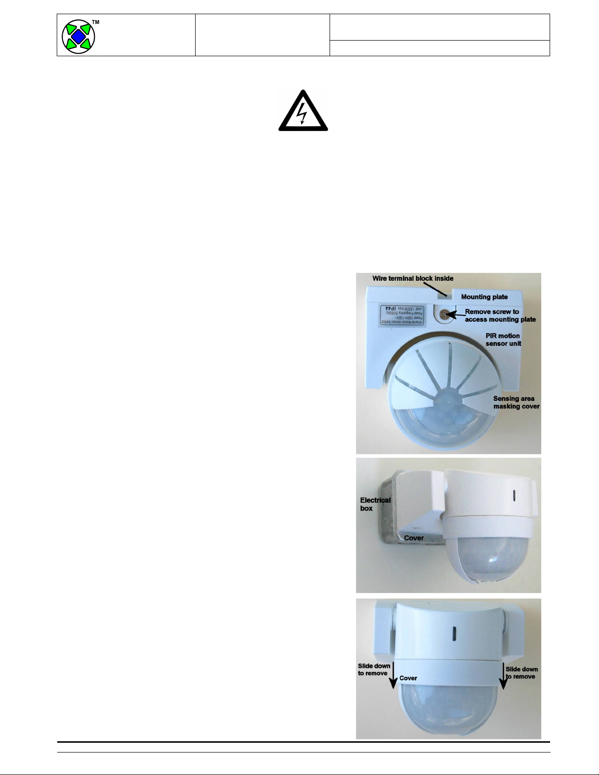
4. Remove screw on the bottom side of the PIR unit to
remove mountin plate. Flip open to remove.
5. The mountin hole spacin on the PIR unit mountin
plate is ~3.28” (sin le- an box spacin ). The
electrical box cover may not have matchin holes.
Center mountin plate on cover plate and mark off
outer mountin hole locations. Drill 3/16” holes or 6-
32 thread holes on cover plate. Protect cover hole
with suitable wire protection ( rommet).
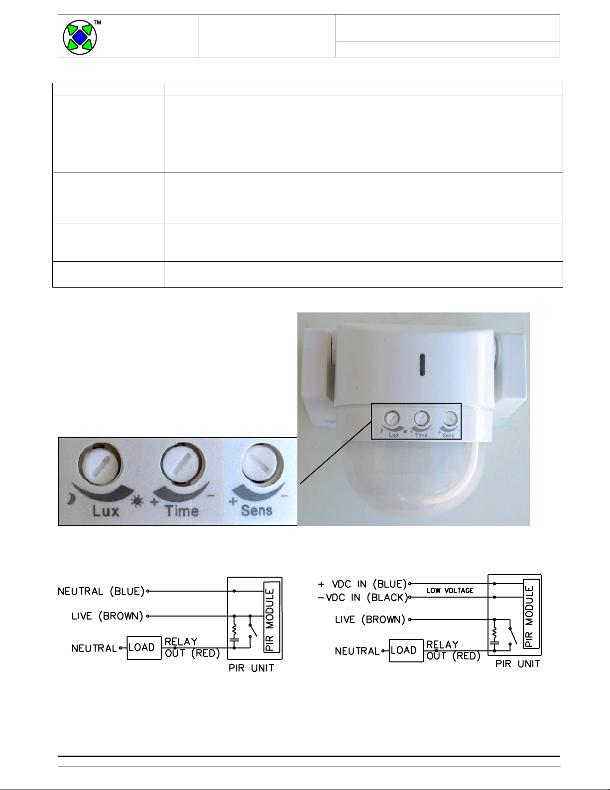
6. Use supplied wires for electrical connection inside
electrical box. Connect power live to brown with twist
cap. Connect power neutral to blue and load neutral.
Connect relay out (red) to load live. The 24VDC
model has blue/black power input and brown/red
relay output control.
7. Pull brown/blue/red wires throu h the center of
mountin plate. It should extend at least 3” outside
the electrical box. Mount PIR unit mountin plate
onto electrical box cover.
8. Loosen the cable clamp on the back of the PIR unit.
Push wires throu h. Pull-out terminal strip. Connect
wires to correspondin colour wires. Insert terminal
strip. Flip PIR unit alon top notches of mountin
plate. Close and ti ht with screw.
9. Remove cover protectin the lens to access
adjustment controls. Apply power. Test and adjust.
Trim and rotate cover to set maskin areas. Test
and adjust.
Parts included:
- 1x Occupancy PIR motion sensor
- mountin screws/hardware
- wires/label sticker
Parts required:
- 1x sin le- an electrical box
- 1x electrical box cover plate with hole.
- tools and eneral electrical hardware