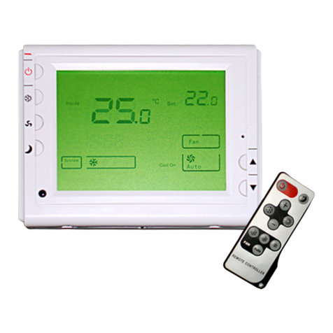
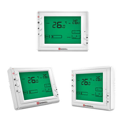
Onyx Controls ONX908MTW-0/24V User manual


1
ONX908MTW-0/24V MULTI STAGE THERMOSTAT
Application: 24VAC,2Heat/2cool
Installation and operation instructions
SPECIFICATION:
Electrical Rating…………………… 24VAC
Terminal Load……………………… 3.0 A per terminal (terminal Y1, W1, G: 5A)
Set point Temperature Range……….. 5℃to 35℃
Dimensions………………………… 115mm×90mm ×28mm
Color……………………………….. White
FEATURE:
Large LCD display with backlight
Set points and room temperature display simultaneously
Maintains the temperature within the range of 0.5℃to the set point
Fan switch with on and auto
Manual change over
Never lost user setting in the event of power-off, no battery is required
Display temperature recalibrates
Sleep mode option
Compressor short cycling protection available
OPERATION
The Thermostat Buttons and Switches The Display
789
1011
12
13
6
5
4
3
2
1
14
Figure 1 Figure 2

(1) Power button
(2) System switch (HEAT, COOL)
(3) Fan switch (AUTO, ON)
(4) Sleep operation button
(5) ▲Raises Temperature setting
(6) ▼Lower Temperature setting
(7) Room temperature
(8) Shows temperature display in ℃or℉
(9) Setting temperature
(10) Indicate fan switch position
(11) Heat on shows when the thermostat
is calling for heat
Cool on shows when the thermostat
is calling for cool.
(12) 1: Shows when thermostat is in the 1st
stage cool or heat mode.
1+2:Shows when both stages begin to
operate in cool or heat.
(13) Shows system mode
(14) Shows thermostat is in configuration
mode.
INSTALLTHE THERMOSTAT
ATTACH THERMOSTAT BASE TO WALL
1.. Remove 2 screws from the bottom of
thermostat. Gently pull the control panel
straight off the base. Forcing or prying on the
thermostat will cause damage to the unit.
2. Connect wires beneath terminal screws on
power supply module using appropriate
wiring schematic. See figure 4
3. Push power base into 86mmX86mm
conduit box.
4. Using two mounting screws mount the power
base to the wall. Place a level against bottom
of base, adjust until level, and then tighten
screws. (Leveling is for appearance only and
will not affect thermostat operation.)
5. Replace control panel on the power base
and fix power base and control panel by
removed two screws in item 1
WIRING DIAGRAM
Screw for mounting thermostat to conduit box
Figure 3
Screw for fixing control panel and power base
Panel base
Control panel
R9
2nd STAGE
HEATING
Y1 W1 GY2 W2 C
FAN CONTROL
CIR CUIT
6
5
2nd STAGE
COOLING
4
1st STAGE
HEATING
2
24VAC
COMMON
1st STAGE
COOLING
24VAC
3
1
7
8
Figure 4
2

CHECK THERMOSTAT OPERATION
Switch on the thermostat
Fan operation
Set fan button to On or Auto
Auto is the most commonly selected
setting and runs the fan only when the heating
or cooling system is on.
Fan On runs the fan continuously for
increased air circulation.
Heat system operation
1. Press system switch to heat mode ( )
2. Press ▲ to adjust thermostat setting above
room temperature. The 1 stage heating
should begin to operate.
3. Both stages of heating system will begin to
operate when the set point is 3℉(2℃)
above ambient. AUX 1+2 display will be
shown. If +2 is flashing, the second stage
will delay 15 minutes before starting. (See
configuration menu 5)
4. Press ▼ to adjust temperature setting
below room temperature. The heating system
should stop operating.
Cooling system operation
1. Press system switch to cool mode ( )
2. Press ▼ to adjust thermostat setting below
room temperature. The blower should come
on immediately, followed by cold air
circulation. If the COOL ON display is
flashing, the 1st stage compressor is at
off-time cycle protection (Note: See
Configuration menu step 6)
3.Both stages of cooling system will begin to
operate when the set point is 3℉(2℃)
below ambient AUX 1+2 display will be
display. If +2 display is flashing, the second
stage will delay 15 minutes before starting
(Note: See Configuration menu item 5)
4. Press ▲ to adjust temperature setting
above room temperature. The cooling
system should stop operating.
If all functions operate properly, the
thermostat is installed correctly.
Sleep operation
Push sleep operation button ,⑤appears indicate during the following 8 hours, the thermostat will
control heating or cooling according to following curve. Push sleep operation button again, disappears
indicate the sleep operation feature is canceled.
time
Temp Cooling Mode
set temp. raise automatically
timer off on sleep operation,
back to former setpoint
Temp. Heating Mode
set temp. decrease
automatically
timer off on sleep
operation, back to
former setpoint
set temp.
-1℃
-2℃
-3℃
+2℃
+1℃
set temp.
Applications
System switch on cool mode: To achieve better sleep, 1 hour after sleeping mode setting, set point
temperature will raise 1℃automatically, and 2 hours later, setting point temperature will raise 2℃and keep on
with this temperature until timer off, which is 8 hours. After timer off, set point will be restored to formal setting
automatically.
System switch on heat mode: To achieve better sleep, 0.5 hour after sleeping mode setting, set point
temperature will decrease 1℃automatically, and1 hour later, setting point temperature will decrease 2℃, 2
hours later, setting will decrease 3℃and keep on with this temperature until timer off, which is 8 hours. After
timer off, set point will be restored to formal setting automatically.
3

CONFIGURATION
The configuration menu allows you to set certain thermostat operating characteristics to your system or
personal requirements. Switch off the thermostat and hold the sleep operation Button for over 3 second till④
power on again means you have entered the first configuration menu item. There are 6 menu items. Press
button to change to the next item. To exit the menu and return to the normal operation, switch off the④
thermostat and switch it on again. If no keys are pressed within 20 seconds the thermostat will be switched off.
Step Press buttons Displayed(factory default)Press▲、▼to select Descriptions
1 ④3 seconds 01 (0) -3 --- +3 Adjust temperature coefficient
2 ④02 (35℃) 20℃—35℃Select maximum setting temperature for heating
3 ④03 (5℃) 5℃—20℃Select minimum setting temperature for cooling
4 ④04 (rd) rd, rE Memorize option before power loss
5 ④05 (FA)FA/SL Second stage fast or slow
6④06 (1 )1、2、3 Display backlight option
7 ④ 06 (On) On/Off Fan option is heating mode.
8 ④ 07 (3) 0,3,5 Minimum compressor off-time setting
1) Select temperature recalibrates Adjustment 3 LO to 3 HI -
You can adjust the room temperature display up to 3 higher or lower. Your thermostat was accurately calibrated
at the factory but you have the option to change the display temperature to match your previous thermostat.
2) Select maximum temperature for heating.
This feature provides a maximum setpoint temperature for heat. The default setting is 35℃, It can be changed
between 30℃to 35℃
3) Select minimum temperature for cooling
This feature provides a minimum setpoint temperature for cooling. The default setting is 5℃, It can be changed
between 5℃to 20℃
4) Memorize option before power loss
Using ▲& ▼button to select between “rE” and “rd”. “rE” means the thermostat will Memorize its ON or
OFF status before power loss. After power supply comes to normal again, the thermostat will remain ON or OFF
according to what it is before power loss. “rd” means no matter the thermostat is switched on or off before power
loss, after the power supply comes to normal again the thermostat will keep power off
5) Second stage fast or slow
Select FAto start 2nd stage immediately when the set point is manually raised more than 2℃in HEAT or
lowered more than 2℃in COOL from room temperature . Select SL, the second stage will delay approximately 15
minutes before starting.
6) Display backlight option
Select 1 the light will be on when any button of the thermostat is touched. Select 2 the display will keep the light
on continuously. Select 3 the display will keep the light off continuously Factory default is 1
7) Fan option in heating mode
If your system requires the thermostat to turn on the fan on a call for heat, select On. If your system
does not require the thermostat to energize the fan on a call for heat such as fossil fuel (gas, oil, etc.), forced
air system as well as hydraulic heating system, select Off.
8) Minimum compressor off-time cycle setting
To protect compressor from short cycling, you can select compressor off-time cycle, 3 means off-time cycle is 3
minutes, 5 means off-time cycle is 5 minutes. When the thermostat compressor time delay occurs it will flash Cool
on display for the time you have selected. Select 0 means you have canceled the function.
4
Table of contents
Other Onyx Controls Thermostat manuals
Popular Thermostat manuals by other brands

Vaughn
Vaughn ETC101 installation manual

VDH
VDH ALFA(NET) 51 PI manual

Lux Products
Lux Products TX9000TS Installation and operating instructions

Heatmaster
Heatmaster Millennium 8000 Series user manual

OJ Electronics
OJ Electronics ETN4-1999 manual

White Rogers
White Rogers 1F80ST-0471 Installation and operating instructions