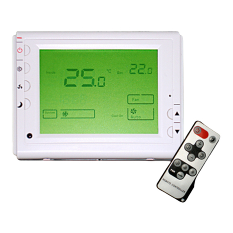
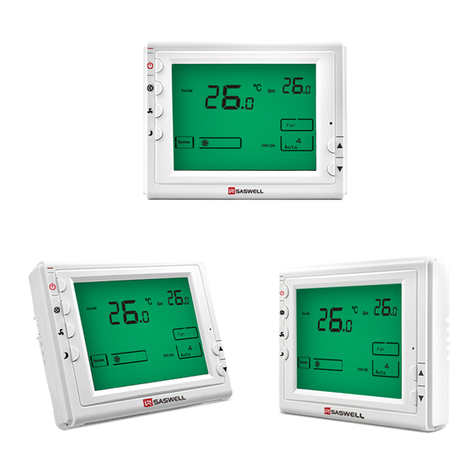
Onyx Controls ONX908PIT-V1-S1-F3/B Service manual


ONX908PIT-V1-S1-F3/B Modulating Digital Thermostat
Installation and operation instructions
The ONX908PIT-V1-S1-F3 modulating digital thermostats are designed to provide
Proportional-Integral (PI) modulating control in 2-pipe or 4-pipe fan coil units, zoned commercial
heating, Ventilating and various heating and cooling applications.
This thermostat provides modulating analog 0-10V or 4-20mA control. Other available
feature includes energy savings card key input, auto-detection of temperature sensor (remote
sensor or internal sensor), and optional Celsius or Fahrenheit operation.
SPECIFICATION:
Input Voltage …………………… 24Vac, 50/60 Hz (Digital Thermostat)
24Vac-250Vac; 50/60Hz (Fan)
Output Voltage ……………… Modulating output 4 to 20mAor 0-10VDC
On/Off output for fan 5A 250VAC
Room temperature setting range………5℃to 35℃(41℉to 95℉)
Accuracy……………………………. ±0.1℉ or ±0.2℃
Dimensions………………………… 115mm×90mm×28mm
Color……………………………….. White
FEATURE:
Large LCD display
The screen displays the set temperature, the room temperature simultaneously
Permanent user setting and program setting retention during power loss,
Special energy saving mode-external input from window contact or hotel card-key overrides
the temperature setting to installer defined heating and cooling temperatures
0-10Vdc or 4-20mAheat and cool outputs
3-speed fan control
Fahrenheit or Celsius display capability
IMPORTANT SAFETY INFORMATION:
Always turn off power at the main power source by unscrewing fuse or switching circuit
breaker to the off position before installing, removing, cleaning, or servicing this thermostat.
Read all of the information in this manual before installing this thermostat.
Only a professional contractor should install this thermostat.
All wiring must conform to local and national building and electrical codes and ordinances.
Use this thermostat only as described in this manual.
1

KEYBOARD, DISPLAYAND SWITCH DESCRIOPTION
(1)
(2)
(3)
(4) (5)
(6)
(8)
(7) (9)
(10)
(11)
(12)
(13)
(14)
(15)
(16)
Figure1 Figure2
(1) Power Button
(2) System Button
(3) Fan Button
(4) Setback Button
(5) Raise Temperature setting button
(6) Lower Temperature setting button
(7) Bar Graph Shows approximate Power Output of Modulation Output
(8) Indicates the Portion of Modulating Output
(9) Setting temperature
(10)Shows temperature display in ℃or ℉
(11) indicates when thermostat is in setback mode. (Energy saving
mode)
indicates when thermostat is in normal operation. (Comfort mode)
(12) Indicates different fan speed
(13) Shows when card key is vacant
(14)Indicates system icon
(15) indicates when there is a call for On/Off heating
(16) Shows Current Read temperature
2

INSTALLTHE THERMOSTAT
ATTACH THERMOSTAT BASE TO WALL
Base
Screw for mounting thermostat to wall
Figure 3
Fixing screw
Control panel
1. Remove 2 screws from the bottom of thermostat. Gently pull the control panel straight off the base.
Forcing or prying on the thermostat will cause damage to the unit.
2. Connect wires beneath terminal screws on power supply module using appropriate wiring schematic.
See figure 4 or figure 5
3. Push power base into wall.
4. Using two mounting screws mount the power base to the wall. Place a level against bottom of base,
adjust until level, and then tighten screws. (Leveling is for appearance only and will not affect
thermostat operation.)
5. Replace control panel on the power base and fix power base and control panel by removed two screws
in item 1 WIRING DIAGRAM
Figure 4
AOUT+AGND-
DC0~10V Or 4~20MA
Modulating Output
Fan
L
M
H
N
L
Occupancy
Switch
11
10
46
5
379
812 13
12
External
Sensor Heating
Relay
OFF
ON
24VAC
3

PERATION
Terminal 12 and 13. The main output of the thermostat is modulating PI analog (4~20mAor
ing
d 8. This output can be used as the main output for heating
ond
ystem Button utton to select among heat mode, cool mode and auto mode.
ge over
ernal sensor installed in terminal 3 and 4. In
e
an Button
itch on three-speed models allows selection of three different settings- (Low/Medium/High)
etback Button button for 5 seconds, the thermostat can shift from comfort mode to setback (energy
ON OFF
Heating
Relay
External
Sensor
2
113
1289
7
356
410 11
Occupancy
Switch
H
ML
Fan
DC0~10V Or 4~20MA
Modulating Output
AGND-
AOUT+
C
24VAC
R
Figure 5
O
Control
Output 1:
0-10Vdc). This signal uses a variable mA signal for the control of analog damper actuator and analog
valve actuator in cooling or heating. (User can select On/Off output by terminal 7 and 9 to control heat
system. See configuration menu item 12)
Output 2:On/off output from terminal 7 an
system or act as the second heating output. (See configuration menu item 12). If it is selected as the sec
heating output, it will activate the second stage heating when the setting temperature is 1℃plus P-band
value higher than room temperature.
S
Pushing system b
Heat mode: Thermostat operates only for heating
Cool mode: Thermostat operates only for cooling
Auto mode: Thermostat operates in automatic chan
Automatic change over function is available only when ext
automatic changeover, the thermostat detects when the system switches between heat mode and cool mod
by comparing the air supply temperature with the ambient temperature. If the thermostat is in heat mode, it
switches to cool mode when the air supply is cooler than ambient by 5℃(9℉) or more. If it is in cool
mode, it switches to heat mode when the air supply is warmer than ambient by 5℃(9℉) or more.
F
Fan speed sw
S
Holding the setback
saving). Factory default setting for setback mode in heating is 18℃and for cooling is 25℃. Shows
indicate you are now in comfort mode while shows indicate you are now in setback mode. Every time
you change the setting in comfort mode, the new setpoint will be memorized as the setpoint of the comfort
mode.
4

You can change the setback setting in configuration menu item 5 and 6
nergy Saving Mode ctivated by a special input from a card key, occupancy switch or window
cont
or example, if the user setpoint is 21℃and the energy Savings Mode setpoint for cooling
(uno
figured within the configuration menu item 13 to be
activ
Dip Switch: A two-way DIP switch allows selection of modulating analog output betw A and
output 4~20mA output
ote: The configuration menu item 15 should match with the Dip Switch Position
ONFIGURATION menu allows you to set certain thermostat operating characteristics to your system
or pe
ton (4) to
ption
as fo
or ºC Readout
dout to Centigrade or Fahrenheit as required.
2)
r or lower. Your thermostat was accurately
calib
EEnergy Saving mode is a
act switch. If the signal via input terminals 4 and 5 is calling for energy saving mode. Then the
thermostat will control to user/installer defined setback setpoints for increased energy savings. The display
will show symbol to indicate when this mode is active. Shows energy saving mode is activated
by input signal. During energy saving mode, setpoint cannot be changed. The setback setpoint can be
change in configuration item No.6 and No.7.Factory default setting for heating is 18℃, for cooling is 25
℃.
F
ccupied cooling setpoint) has been set to 28℃, then the thermostat will control to 28℃when the
input signal activated the Energy Saving mode. .
The energy saving mode input can be con
ated either a short circuit (default) or open circuit signals.
een 4 to 20m
0~10V. Open the thermostat, you will find the JP6 in the rear board. Following figure showing you how to
select 0~10V output and 4~20mA output via change the dip switch position.
0~10V
N
C
Configuration Menu
The configuration
rsonal requirements. Switch off the thermostat. Hold button (4) for 5 seconds to enter the
configuration menu. The display will show the first item in the configuration menu 1. Press but
shift to the next menu item. Use ▲、▼to select. To exit the menu , pressing button (1) to switch off the
thermostat. If no buttons are pressed within 20 seconds the thermostat will exit the menu. To revert to
factory default setting , push (2) button for 3 seconds. Display will show “DEF” blinking 3 times and
return to Menu item 1 indicates all the configuration setting has reverted to factory default setting.
The configuration menu chart summarizes the configuration options.An explanation of each o
llows:
1) Select ºF
Changes the display rea
Select temperature recalibrates Adjustment 3 LO to 3 HI –
You can adjust the room temperature display up to 3 highe
rated at the factory but you have the option to change the display temperature to match your previous
thermostat. The current or adjusted room temperature will be displayed on the right side of the display.
0~10V
4~20mA
0~10V
4~20mA
4
5
Card
5

Item Press buttons Displayed(factory
default)
Press▲、▼to select Description
1 (4) For 5 second FC (℃) ℃/℉ Select ºF or ºC Readout
2 (4) CL (0) -3 --- +3 Select temperature display adjustment higher
or lower
3 (4) CH (35℃/95℉) 18 ℃ (64 ℉ )—35 ℃ (95
℉)
Select maximum setpoint
4 (4) CC (5℃/41℉) 5℃(41℉)—20℃(68℉) Select minimum setpoint
5 (4) UC (25℃/77℉) 25℃(77℉)-30℃(90℉) Select setback point for cooling
6 (4) UH (18℃/65℉) 10℃(50℉)- 18℃(65℉) Select setback point for heating
7 (4) PH (2) 0-10 Select P-band
8 (4) LP (5) 1-10 Integral action time
9 (4) FH (100) (50-100) Maximum integral part
10 (4) FL (0) (0-50) Minimum of integral part
11 (4) bL (1) 1/2/3 Select display backlight mode
12 (4) HF (h1) h1/OF/h2 Heating output type option
13 (4) En (AC) OU/AC Active temperature sensor
OU:Return air temperature sensor active
AC:Room temperature sensor active
AU: Mix temperature sensor active
13 (4) rC (SC) SC/OC/OO Activate energy saving mode option
14 (4) U (I) U: 0–10 VAC output
I: 4 - 20 MA output
Choose the control mode between 0~10VAC
output to 4~20MAoutput
15 Press Power Button return to close
3) Select maximum temperature set point
This feature provides a maximum set point temperature. The default setting is 35℃(95℉), It can be
chan
int temperature. The default setting is 5℃(41℉), It can be
chan
nt temperature for heating. The default setting is 16℃, It can
be ch
t for cooling etpoint temperature for cooling. The default setting is 25℃, It
band is the amount of change required by the ambient temperature for the output to
ged between 18℃(64℉) to 35℃(95℉)
4) Select minimum temperature set point.
This feature provides a minimum set po
ged between 5℃(41℉) to 20℃(68℉)
5) Select energy saving setpoint for heating
This feature provides energy saving setpoi
anged between 10℃to 18℃
6) Select energy saving setpoin
This feature allows you to set energy saving s
can be changed between 25℃to 30℃
7) Select P-band
The proportional
go from 0 to 100%. It can be adjust from 0~10℃. Factory default setting is 2℃. For example if the
6

P-band is set in 2℃in the heat mode, with a 25℃set point and an ambient temperature of 25℃, th
modulating output is 0%; at 24℃the output is 50%; and at 23℃the output is 100%. The intergral
gain implies that the longer the error between the ambient and the set point temperatures exists, the
more the output will change to eliminate the error. The integral portion of the algorithm eliminates th
temperature offset from the set point.
e
e
eat mode (P-band: 2℃) re is below the set point the output is somewhere between 0~100%
ool mode(P-band: 2℃) ure is above the set point the output is somewhere between 0 and 100%
) set the integral action time for the integral to run from 0 to 100%. The
valu
imum integral portion ximum modulating output. For example, if you set the maximum
10) imum modulating output. For example, if you set the maximum
F ure 5
of Output
10V
or20mA
0%
50%
100%
H
When the ambient temperatu
%
4-
ig
C
When the ambient temperat
8 Select integral action time
This feature allows you to
e required depends on the reaction time of the control loop. If the time is chosen too short, the control
loop will become instable and oscillate. If the time is chosen too long, the control loop will become
sluggish.
9) Select max
This feature allows you to set the ma
integral portion to 80%, the maximum modulating output will be 8V or 16.8mA.
Select minimum integral portion
This feature allows you to set the min
integral portion to 20%, the maximum modulating output will be 2V or 7.2mA.
11) Display backlight option
0-
+3+2+1
Set point
-1
-2
-3
-3 -2 -1 Set point +1 +2 +3
100%
50%
0%
% of Output
0-10V
or
4-20mA
Figure 6
7

Select 1 the light will be on when any button of the thermostat is touched. Select 2 the display will keep
th
l output for heating control is available, terminal 12 and 13 (See Figure 4) is
Figure 4) is the On/Off
tive. Terminal 12 and 13 (See Figure 4) is used as 0-10V or 4-20mAmodulating
13) tive temperature sensor
perature sensor option.
r seasonal changeover
14) y to activate the energy saving mode.
5) Shift between 0~10VAC output to 4~20MAoutput ode between 0~10VAC output to 4~20MA
outp Do not forget to change the position of the dip switch so that it can match with
After reading this guide, if you ha tion of your thermostat, please
e light on continuously. Select 3 the display will keep the light off continuously Factory default is 1
12) Heating type option
‘h1: Only proportiona
used as 0-10V or 4-20mA modulating output to control heating or cooling
OF: Only On/Off output for heating control is available. Terminal 7 and 8 (
output to control heating. Terminal 12 and 13 is used as 0-10V or 4-20mAmodulating output to
control only cooling.
‘h2: 2 stage heating ac
output to control 1st stage heating. Terminal 7 and 8 (Figure 4) is the On/Off output to control 2nd stage
heating.
Select ac
This feature provides two active tem
Select OU means return air temperature sensor active
Select AC means room temperature sensor active
Select AU means mix temperature sensor active fo
Activate energy saving mode option
This feature allows you to select the wa
Select OC to activate the energy mode by open circuit
Select SC to activate the energy mode by close circuit
Select 00 to cancel the energy mode
1This feature allows you to select the way to shift the m
ut.
NOTE:
output option. (See dip switch in Operation Chapter)
CUSTOMER ASSISTANCE
ve any question about the opera
contact your installer or Energy Utility company or service provider.
8
Table of contents
Other Onyx Controls Thermostat manuals
Popular Thermostat manuals by other brands

Uponor
Uponor T-26 quick guide

Siemens
Siemens TH 192 S installation instructions

Lennox
Lennox icomfort quick start guide

DELTA DORE
DELTA DORE DELTA 8000 TAP RF installation instructions

OJ Electronics
OJ Electronics OCC4 user manual

White Rodgers
White Rodgers 1F80-361 Installation and operation instructions