Open Date Thermocode Series 2 Specifications

THERMOCODE SERIES 2
OPERATOR INSTRUCTIONS
CIRCUIT DIAGRAMS
INSTALLATION DETAILS
Continuous “53CR” Left Hand
Thermal Transfer Printer
Designed and manufactured by: -
OPEN DATE EQUIPMENT LIMITED
Units 8 & 9 Puma Trade Park
145 Morden Road
Mitcham
Surrey CR4 4DG
UNITED KINGDOM
TEL: - 0044 (0) 20 8655 4999
FAX: - 0044 (0) 20 8655 4990
Web Site: - http://www.opendate.co.uk/
Technical website: - http://www.opendateinfo.com/

Thermocode 2 Printer manual Version 2.04 January 2011 2
EC DECLARATION OF CONFORMITY
2
We hereby declare that the following machinery complies with the essential health and safety
requirements of the Machinery Directive 89/392/EEC enacted in the United Kingdom by the Supply
of Machinery (Safety) Regulations 1992. Amended 1999 (URN 99/1232) Amended 2005
Machine Description: Thermal Transfer Printer. Model:
Type: Thermocode Series 2 Serial Number:
Manufactured by: Open Date Equipment Limited.
Units 8 & 9 Puma Trade Park,
145 Morden Road,
Mitcham,
Surrey.CR44DG
England
Telephone: - 0208 655 4999
This machinery has been and manufactured in accordance with the following transposed harmonised
European standards.
EN ISO 12100: parts 1 and 2, 2003. Safety of Machinery - Basic concepts, general principles of design.
EN 294: 1992. Safety of Machinery - Safety distances to prevent danger zones being reached by the
upper limbs.
EN 60204: part 1, 2006. Safety of Machinery - Electrical equipment of machines - Specification for
general requirements.
EN 61000 – 6 - 2: 1999. Electromagnetic compatibility - Generic immunity standard.
EN 61000 – 6 – 3: 2001 Electromagnetic compatibility - Generic emission standard.
(IEC 61000-6-2: 1999,modified)
EN 61000: 3 - 2, 2001. Harmonic Emissions.
EN 61000: part 3 – 3, 1995. Voltage Flicker.
FCC Part 15, Conducted & Radiated Emissions, Class A.
In addition, this machinery has been designed and manufactured in accordance with British Standard
PD 5304: 2005, Safety of Machinery.
A technical construction file for this machinery is retained at the above address.
Signed: Date:
Name: Position:
Being the responsible person appointed by Open Date Equipment Limited.
This Declaration of Conformity complies with Regulation 22 of The Supply of Machinery (Safety)
Regulations 1992 Amended 1999 (URN 99/1232)

Thermocode 2 Printer manual Version 2.04 January 2011 3
Index
3
Page No.
ThisPage 3
Standard Warranty Terms and conditions 4
SafetyInstructions. 5
Introduction. 6
System Overview. 6
Optional Extras. 6
Printer Technical Information 6
Installation Procedures 7 - 10
SettingtheFiveVolts 11
ControlRelays 12
Power Supply (I/O Board connections) 13
Power Supply (PNP / NPN Sensors & Volt Free print signals) 14
Power Supply (fuse details etc) 15
Power Supply (LED details) 16
Encoder Description 17
Encoder & Lower Roller Unit, Power Supply Wiring Connections 18
Encoder Types and Wiring Connections 19
System Start Up Sequence 20 - 21
Mini-Terminal Key Mapping 22
Mini Terminal Flow Charts 23 - 29
Quick Selection Reference Sheets 30 - 32
Thermal Ribbon Specification 33
Threading Diagram 34
Cleaning 35 - 36
Fault Finding. 37 - 40
Ribbon Not Indexing Enough, Ribbon Indexing Excessive 37
Ribbon Breaking or Perforated, Ribbon Tracking. 37 - 39
Print Quality Problems 39
Clearing Printer Error Messages 39
Thermocode Diagnostics Sheet 1 40
Thermocode Diagnostics Sheet 2 40
Error Codes 41 -48
Automatic Burn Compensation As Speed Changes 49
Magazine Spares 50
Dimensions
PrinterDimensions 51
Standard Frame Dimensions 52
Lower Roller Unit Dimensions 53
Power Supply (Dimensional and Installation Details) 54
Computer Connection leads. 55
Airborne Noise Emissions 55
Open Date Group Companies Addresses 56

Thermocode 2 Printer manual Version 2.04 January 2011 4
4
Standard Warranty Terms and Conditions – Thermocode Series 2 Printers
Open Date thermal transfer printers carry a twelve (12) month return to base (at our discretion) warranty,
with the exception of the following parts: -
1. Thermal Printhead.
2. Lower Roller. (Rubber covered Roller)
3. Cassette Springs and Belts.
4. Cassette Rubber Drive Roller.
Static Electricity
Warning, static electricity may damage the printer or printhead. On many film type installations, the material
produces static electricity and possibly causes printer problems or printhead failure. Open Date does not
accept any type of warranty claims, if any damage to the printer or Printhead is caused by static electricity.
If you are in doubt about your installation, please contact our service department.
Printhead Warranty
The Printhead assembly (ASY762199, ASY762200, ASY762345 or ASY762346) carries a 50 kilometres or
12 months warranty which ever is the soonest. Should the Printhead fail during this period, the replacement
Printhead will carry the balance of the existing warranty.
Please refer to the ribbon specifications sheet on page 33, check the correct width of thermal transfer ribbon
is being used and has the appropriate silicone back coating to protect the Printhead.
The Printhead warranty will not be valid if: -
1.The full width ribbon is not being used, as excessive wear on the edges of the Printhead
can be found. (See page 33)
2. Mechanical damage is apparent from abuse.
3. The Spy Chip Board has been removed or damaged in any way.
4. Cleaning Procedures have not been followed. (See pages 35 & 36
5. Installation and maintenance procedures are not correct. (See pages 6 – 10)
6. The print base used (Lower roller unit) or roller is not as specified. (See page 53)
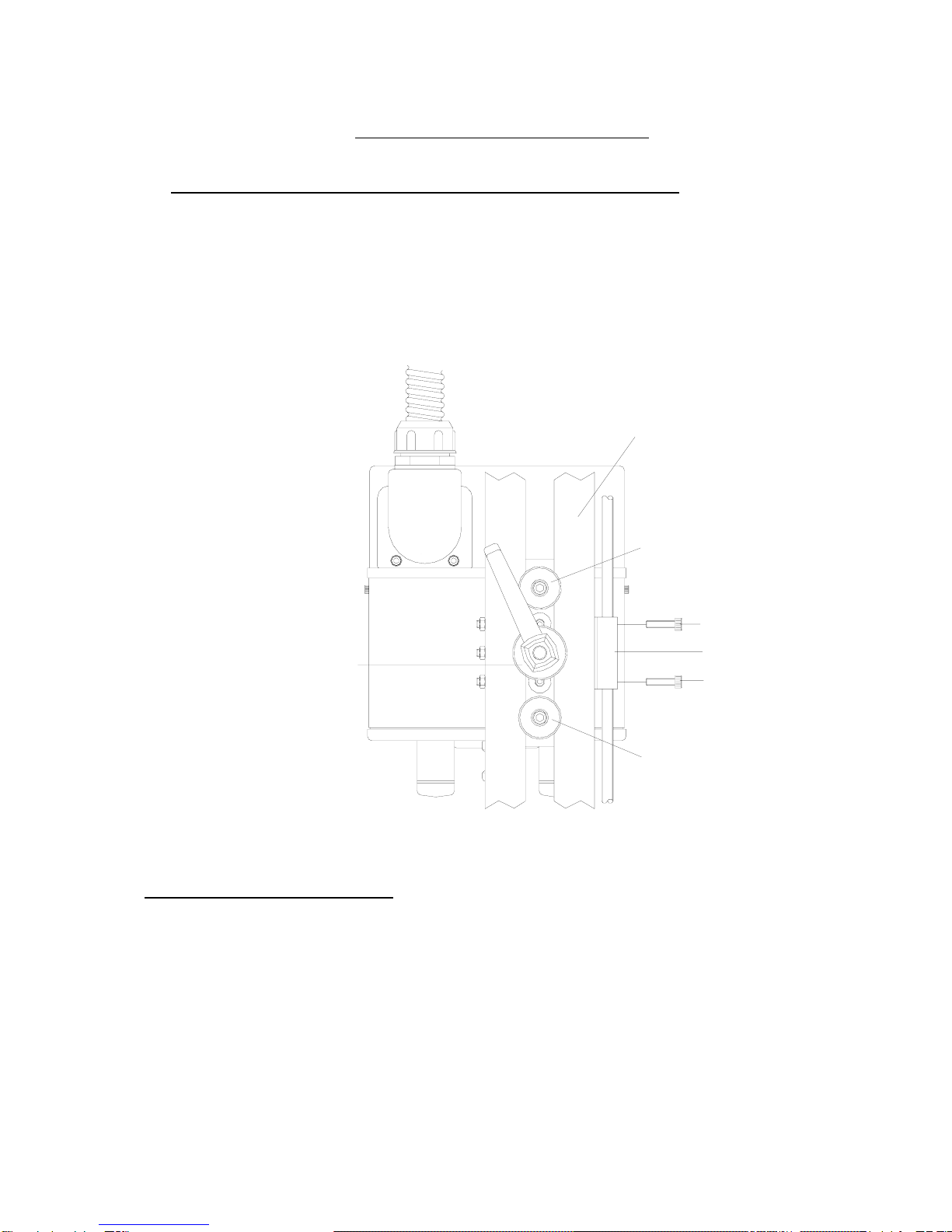
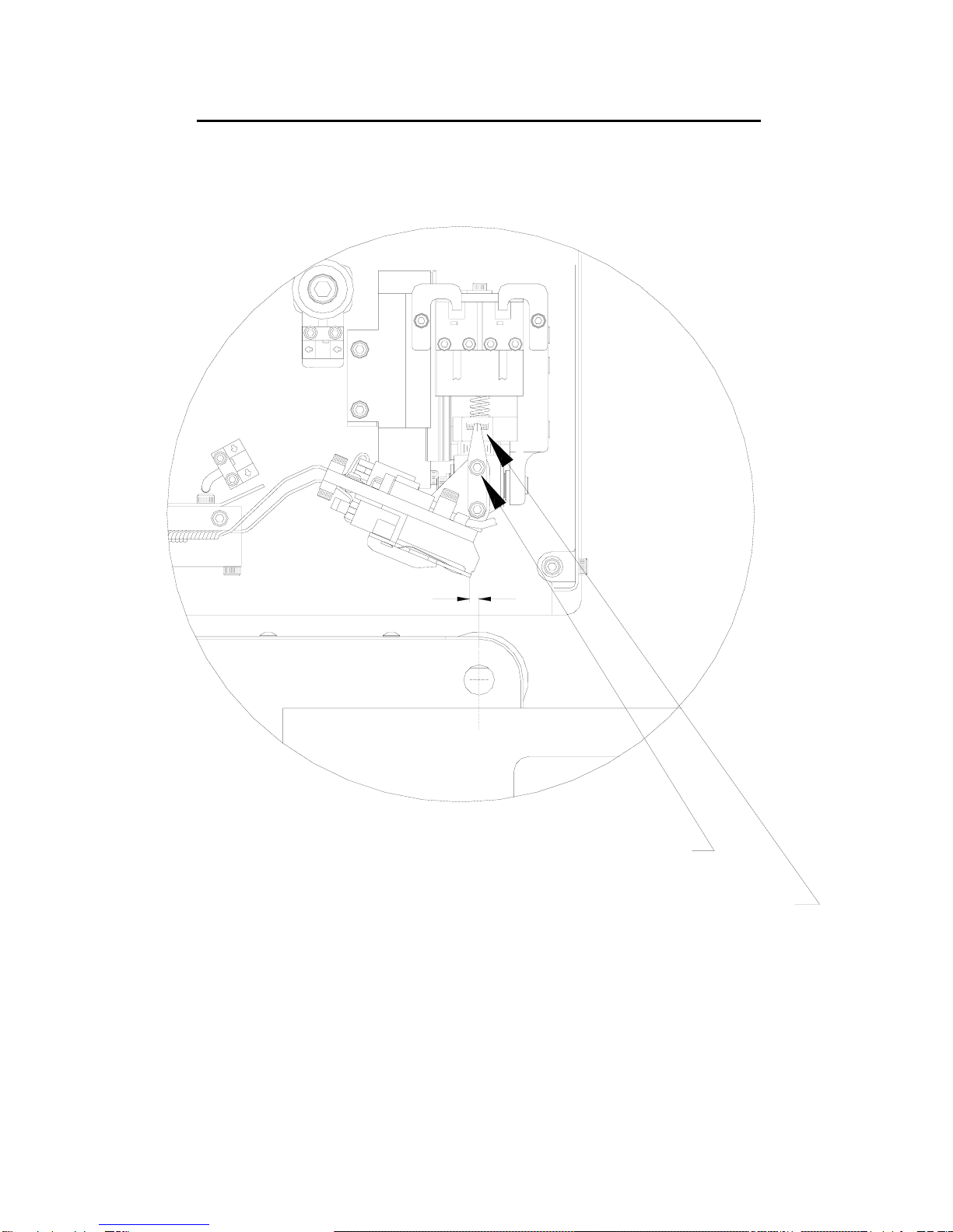
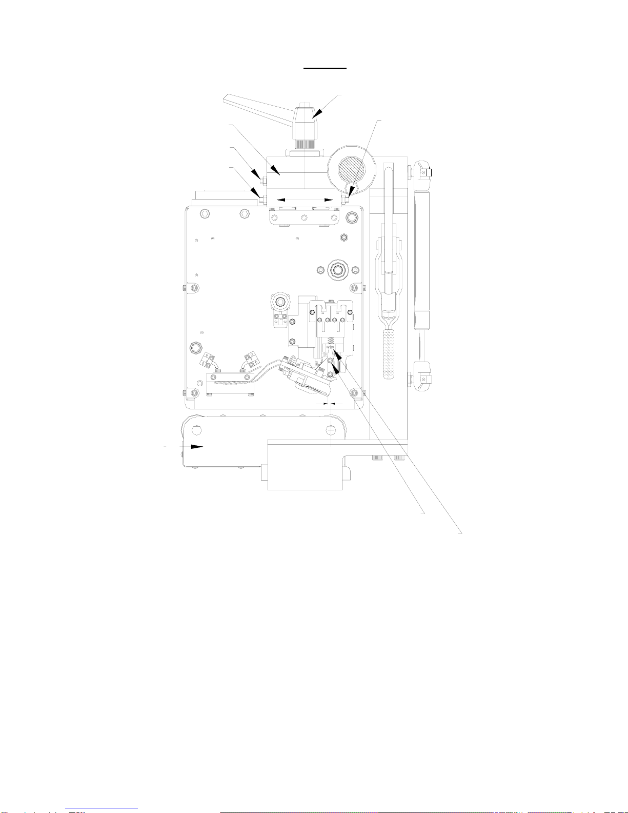
7. The Printhead angle has not been set up correctly. (See page 7 – 10)
8. Static Electricity is found.
9. Recommended Open Date ribbon is not being used. (See page 33 Ribbon Specifications)
10. Printing substrate or ribbon is found to be abrasive.
The print base or lower roller assembly carries no warranty, as it is considered to be a consumable item.
We reserve the right to charge for components replaced during the warranty period, which are found
damaged due to any of the above conditions not being followed or met.
Printhead Spy Chip
Contained within the Printhead assembly, is a small microchip this is programmed when the head is first
assembled and tested to retain the following information: -
1. Printhead resistance value (ohms).
2. Printhead width (Dots).
3. Printhead serial number.
4. Printhead data lines.
5. Programmed factory date.
6. Printhead angle.
During start up of the printer, the Spy Chip is accessed by the software, determining the width of printhead
and automatically adjusts the resistance value to compensate for the correct print burn calculations. Whilst
printing, the spy chip is written to, allowing automatic recording of the print distance achieved during the life
of the printhead.
All the Printhead recorded settings may be viewed at any time, by accessing the Service menu on the mini-
terminal Display.

Thermocode 2 Printer manual Version 2.04 January 2011 5
5
IMPORTANT SAFETY INSTRUCTIONS
1. Read these instructions carefully. Follow all warnings and instructions marked on the product.
2.
A
lways disconnect the printer and Power Supply from the mains electrical supply before attempting
to clean or service the product.
3. Never operate the printer, unless it is installed within the mounting frame supplied. When installed
correctly, the gap between the printer and print base should be nominally 1mm.
4. Do not use the product near water. Never spill liquid of any kind on to the product.
5. Do not place this product on an unstable stand, table or machine. It may fall causing serious injury to
the operator or damage to the product.
6. Never insert objects of any kind into this product through any openings or gaps as they may touch
dangerous voltage points or short circuit parts that could result in fire or electric shock.
7. This product should only be connected to the type of electrical supply as indicated on the label
located on the top of the Power Supply. (See CE label)
8. Ensure that the printer connection cable is fully secured to the printer and power supply with the
screws supplied. Failure to do this will result in the machine not being properly earthed.
9. Use only the power cable supplied with the product. The cable supplied is three core, utilising one
wire as a grounding conductor. This must be connected to a suitable earth point at the electrical
supply. This is a safety feature. If any doubt arises in trying to connect the power cable, please
contact the manufacturer or the agent who supplied the product.
10. Do not allow anything to rest on the power cable. Do not locate the product where people could walk
on the cable.
11. If an extension cable is used with this product, make sure that the total ampere ratings of the
equipment plugged into the extension cable does not exceed the extension cable ampere rating.
Also make sure that the total rating does not exceed the fuse rating.
12. Do not service this product yourself as opening or removing guards may expose you to dangerous
voltages, major burns and other risks. Refer all servicing to qualified personnel.
13. Do not attempt to use to use this product in areas where explosive gases or substances are present.
14. Under the following conditions always disconnect the electrical supply and refer to a qualified service
engineer.
a. If the power cable is damaged or frayed.
b. If the printer connection cables are damaged in any way.
c. If liquid has been spilled into the product has been exposed to water.
d. If the product does not operate normally when the operating instructions are followed.
15. Adjust only those controls covered by these instructions. Improper adjustment could result in permanen
t
damage, requiring qualified technicians to restore the product to normal operating conditions.
16. Do not touch the printer or control box with wet or moist hands.
17. Do not use the Printer without Thermal Transfer Ribbon, as the printhead maybe damaged.

Thermocode 2 Printer manual Version 2.04 January 2011 6
6
Introduction
This operator manual describes how to operate and maintain a Thermocode Series 2 (Model 53CR) on a
basic level. The mechanical adjustments that can be made to the printer are minimal. Normally the printer is
installed in a standard frame, which allows the correct clearance from the lower roller unit and the alignments
deemed needed.
Operation of the printer is either by selection of a stored format within the printer memory, or by designing a
dedicated format from the windows software and then downloading from a standalone computer.
Using the mini-terminal, formats can then be selected and edited by the operator as required.
If you are making your own frame or installing into a specific type of machine, you must consult the
manufacturer to ensure you receive the correct detailed dimensions required for your installation.
SYSTEM OVERVIEW
The following components are supplied ready for installation.
1 Thermocode Model 53CR
1 Power Supply Unit (240 Volt or 110 Volt) Selectable inside the unit
1 Mini-Terminal display
1 Power Supply Interconnection Lead 1.5 metres long
(Available in 3, 5 or 6 metre lengths see page 11)
1 Roll of Thermal Transfer Ribbon (300 metres x 55 wide, Wax Resin quality)
1 Operator Manual
1 Printhead Cleaning Kit, Consisting off 50 Print head Cleaning Wipes (Isopropyl Alcohol)
1 Programming lead (3 Metre length, 9 way “D” connector)
. 1 Recover Mode software backup program (Allows customer to back up all printer data)
OPTIONAL EXTRAS
Windows based Software (Codesoft Premier package with Installation & details manual).
Encoder, rotary incremental (see pages 17 – 19)
Lower Roller Unit. (Custom Designed to fit the Open Date Frame)
Standard or custom designed mounting frame.
Ethernet & USB Communications (RS232 is standard)
PRINTER TECHNICAL INFORMATION
Maximum print area = 53.3mm X 500mm.
Printhead resolution in dots 12 dots/mm or 305 dots per inch.
3.5 Megabytes (approximately) memory for storing fonts, graphics and custom designed formats.
Print designs are stored along with all parameters, allowing quick access for printing.
Automatic updating of printer memory when editing formats.
Supply Voltage 110 or 220 / 240 V 50/60hz.
Real Time/Date printing with specified offsets if required.
Sequential Numbering and Barcode printing
All text, graphics, lines and boxes can be printed in all four orientations. (0, 90, 180, 270 degrees)

Thermocode 2 Printer manual Version 2.04 January 2011 7
7
INSTALLATION PROCEDURES
Installing the 53CR Continuous Printer on a Standard Continuous Frame
1. Install the right hand printer into the Standard Continuous frame, utilising the “location sleeves” and
then lock the “clamp handle” (see below)
2. Fit the retaining screws for the linear block adjustment. (See below)
LOCATION SLEEVE & FIXING SCREW
CLAMP HANDLE & WASHER LINEAR ADJUSTMENT BLOCK
LINEAR BLOCK FIXING SCRE
W
LINEAR BLOCK FIXING SCRE
W
FRAME TOP SLOTTED BAR
Checking the Printhead Angle
1. Check the “printhead angle” has been set correctly remove the magazine to visually check the
mechanical angle setting. Within the mini-display unit, select the “Service Menu” number 4
Print head data, and check the printhead angle has been set correctly.
If the angle does not correspond, release the “Printhead Locking Screws” and adjust until the
pointer is set correctly (See fig 2a Page 8) It may be necessary to switch off all electrics and
remove the printer to a well-lit area to carry out this fine adjustment.

Thermocode 2 Printer manual Version 2.04 January 2011 8
8
Enlarged View of Printhead and Pressure Roller Alignment
1.00 mm
CENTRE LINE ROLLER
PRINTHEAD LOCKING SCREWS
CHECK PRINTHEAD ANGLE
FIG 2a

Thermocode 2 Printer manual Version 2.04 January 2011 9
9
FIG 2B
PRINTHEAD SUPPORT ASSEMBLY
ADJUSTMENT
UPPER SCREWS A & B
LOWER ROLLER UNIT
LOWER SCREW D
LOWER SCREW C
CHECK PRINTHEAD ANGLE
CLAMP HANDLE
PRINTHEAD LOCKING SCREWS
CENTRE LINE ROLLER
1.00 mm
FIG. 2
Align the Printer to be adjusted correctly in the Standard frame, set the Printhead to be behind the print
roller centre-line at “1.0 mm” dimension. (See above)
A. Release the “Clamp Handle” by a quarter turn. (See above)
B. Adjust the “Lower Screw D”, undo by half a turn. (See above)
C. Adjust the “Lower Screw C”, do up by half a turn. (See above)
(Lower Screw C is the opposite side of the frame)
D. Lock up Clamp Handle. (Once correct, lock up lock nuts)

Thermocode 2 Printer manual Version 2.04 January 2011 10
10
Alignment of right hand Printer to the Lower Roller Unit
A. Release the “Clamp Handle” by a quarter turn. (See below)
B. Adjust the “Upper Screw B”, undo by half a turn. (See below)
C. Adjust the “Upper Screw A”, do up by half a turn. (See below)
D. Lock up Clamp Handle.
E. Test a print an image, to show the printer is aligned to the Lower roller Unit.
CLAMP HANDLE
CLAMP WASHER
UPPER SCREW "A"
UPPER SCREW "B"
If the printer is aligned opposite to the above shown diagram, just reverse the adjustment
procedure. By Adjusting the “Upper Screw A” before “Upper Screw B”.
You may have to repeat the procedure to ensure the printhead is aligned to the lower Roller unit correctly.
Installation Notes
1. Installing the Thermocode 53CR printer in a Standard mounting frame may not be required, but please
check that all frame dimensional details needed are attained. It is very important that the alignment to the
print roller is correct (see pages 8, 9 & 52
2. frame details etc.)
3. Connect the printer and power supply using the interconnection lead supplied. The lead has been
specifically designed, so it cannot be fitted incorrectly. Please ensure that the plugs and sockets are
inserted fully before tightening the fixing screws. Orientation of the mounting plate can be changed, by
removing the two fixing screws. Then rotating the mounting plate.
4. Each installation must have an automatic print signal from the parent machine, this is normally a relay
(voltage free) or 24 Volt pulsed output signal.

Thermocode 2 Printer manual Version 2.04 January 2011 11
11
Five Volt Adjustment
If a Printer is to be fitted with a special length interconnection cable (3, 5 or 6 Metres), please ensure
that the 5 Volt DC supply at the Printer is adjusted to 5.1 Volts, otherwise the Printer may not
function correctly. This can be measured on Pin 5 and Pin 9, of the 9way “D” serial socket. The
voltage is adjusted via the Potentiometer on the front right hand side of the power supply.
See page 15
Test Connector not supplied
Plug in to the Serial Port of the Printer
Check the voltage with a Multi-meter
For more information on the Power Supply see: -
Page 12 & 13 for relay connections.
Page 13 & 14 for print signal connections.
Page 15 & 18 for power supply plan view (Page 15 with covers removed)
Page 18 & 19 for power supply Encoder Connections
The print signal can be delayed upon installation if required. Within the Supervisor menu on the mini-
terminal display, there is a “Delay Menu” which allows the operator to change the print signal delay
time. (Range 0 to 999 milliseconds)

Thermocode 2 Printer manual Version 2.04 January 2011 12
12
Thermocode Series 2 Controlling Relays
Within the Thermocode Series 2 Power supply are three relays, which can provide controlling
signals to the parent machine. Each relay has three connections, Normally Open, Normally
Closed, and Common. (Also see page 13)
The relays have a maximum rating of 240 Volt, 7 Amp. Through the Mini-Terminal software the
installation engineer can configure each of the relays as required. (To set the options see page 28)
Relay 1 (4 options)
<0> Stop Machine
The relay operates after each print cycle giving a trigger/inhibit signal to the parent machine
after printing or when the cassette is removed.
<1> Sequence (default software setting)
The relay operates after each print cycle giving a trigger/inhibit signal to the parent machine
after printing.
<2> Ready
The relay operates when print images are being generated etc. (When the printer is off line)
<3> Future Development
<4> 100ms pulse
The relay is pulsed for a 100 milliseconds
Relay 2 (5 options)
<0> Start Machine
The relay operates after each print cycle giving a trigger/inhibit signal to the parent machine
after printing or when the cassette is removed.
<1> Low Foil (default software setting)
The relay operates when the amount of Thermal Ribbon left in metres reaches a pre-
programmed amount, and is visually indicated to the operator “Low Foil” on the status line of
the Mini-Terminal Display.
<2> Ready
The relay operates when print images are being generated etc. (When the printer is off line)
<3> 100ms pulse
The relay is pulsed for a 100 milliseconds
<4> 100ms pulse
The relay is pulsed for a 100 milliseconds
Relay 3 (4 options)
<0> Fault Only
The relay operates when the printer’s internal sensors detect a fault or error condition.
Typical examples of this are when the Cassette is removed or if the Thermal Ribbon is
broken.
<1> Fault & Ready (default software setting)
The relay operates as option 1, but will also operate when print images are being generated
etc. The relay should be connected to inhibit the parent machine should any printer fault
occur.
<2> Future Development
<3> 100ms pulse
The relay is pulsed for a 100 milliseconds
<4> 100ms pulse
The relay is pulsed for a 100 milliseconds

Thermocode 2 Printer manual Version 2.04 January 2011 13
13
Power Supply (I/O Board connections)
(fit Print Signal Selectors to positions "J" & "L" only)
Input (6 - 35 volt AC):- Connect wires to terminals 3 & 4, polarity unimportant.
(fit Print Signal Selectors to positions "J" & "L" only)
Input (9 - 50 volt DC):- Connnect wires to terminals 3 & 4, polarity unimportant.
(fit Print Signal Selector to "M" only as shown)
Voltage Free Connections:- Connect wires to terminals 1 & 2.
Print Signal Inputs
10
2 = "Ready"
1 = "fault & Ready" (Default)
Spare Link
Default Software Setting
0 = "fault" RELAY
3N/C
N/O
COM
1 = "Low Foil" (Default)
0 = "Start Machine"
1 = "Sequence" (Default)
0 = "Stop Machine"
Default Software Setting
C = Standard Relay
A = Reed Relay
Relay 1 Output Choice.
2 = "Ready"
B = Transistor
RELAY
RELAY
2
1
N/O
COM
N/C
N/C
N/O
COM
B
C
A
RR1
RR2
TRO
TRN
contact bounce. ie heavy
6
Print Signal Selector Link
duty relays or switches etc.
PCB 763068
1
3
2
4
5
JH MLK
Reed Relay Connection
(Max 350V ac/dc 0.75A, 1.5ms)
Reed Relay Connection
(Max 350V ac/dc 0.75A, 1.5ms)
Fit link for input signals with
Link E & F for "Falling Edge"
Link D & G for "Rising Edge"
Auxillary Contacts:-
(Rated 100v DC, 3 amp max.)
Transistor NPN output
(Link to the machine "O" volt)
Transistor "O" Volt.
8
7
9
D
F
G
E

Thermocode 2 Printer manual Version 2.04 January 2011 14
14
PNP / NPN Sensor or Volt Free Connections
Note: - The above drawings, are for 24V DC sensor deriving their power from the Thermal power supply.
When the sensor has its own power supply, leave off the +24V connection
1
10
1
10

Thermocode 2 Printer manual Version 2.04 January 2011 15
15
Power Supply
Note: - All Stepper drive boards are the same. Part No. PCB 763004
I/O Board
Part No. PCP763005 Pressure Motor Set
to low power Lower Roller Unit Set
to high power Ribbon Motor set to
high power
Linear Motor leads
Not used.
Mains fuse 5 amp Anti-surge
Part No FUS 753016
24 Volt DC Switching Board
Part No PCB 763006
Fuse 20 am
p
& USA 15 am
p

Thermocode 2 Printer manual Version 2.04 January 2011 16
16
THERMOCODE SERIES 2 (Power Supply LED details)
24 VOLT PRINTHEAD OPERATION LED
PRINTHEAD 24 VOLT SUPPLY LED
PRINT INPUT SIGNAL LED
STEPPER MOTOR 40 VOLT SUPPLY LED
POWER SUPPLY 5 VOLT LED
PRINTER 5 VOLT SUPPLY LED
PRINTER DISPLAY 9 VOLT LED
24v
PH OP
PH
SIG
IP
PR
9v
PR
5v
PS
5v
M
40v

Thermocode 2 Printer manual Version 2.04 January 2011 17
17
Encoder Description
Incremental encoders are commonly used as feedback devices for motor controllers. They also serve as
operator interfaces and are sometimes called rotary pulse generators.
An incremental encoder is made up of 2 major parts: the internal disk and the sensor. The disk of an
incremental encoder is patterned with a single track of repeating identical lines near the outside edge of the
disk. The number of line pairs on the disk determines the encoder resolution.
Our standard encoder wheel has a circumference of 200mm and runs on the surface of the substrate.
Thermocode Series 2 requires 2400 pulses per revolution.
Since the resolution of the Printhead is 12 dots per mm, we also require 12 pulses per mm down the web.
Therefore one revolution of the encoding wheel is 200mm X 12, equals 2400 pulses.
Principles of an Incremental Encoder
The Open Date Equipment standard encoder assembly is fitted with a measuring wheel on the output shaft,
you will have to provide specific sprung loaded designed brackets to mount the unit on the parent machine.
(Open Date Equipment Ltd can supply standard mounting brackets. Contact your local supplier)
You must ensure that no slipping happens between the substrate and the measuring wheel, otherwise
printing quality, print registration or printer errors could occur.
If you need to fit an encoder inside a parent machine, not just running against the substrate I suggest you
contact Open Date Equipment Ltd for technical assistance.

Thermocode 2 Printer manual Version 2.04 January 2011 18
18
Power Supply Shaft Encoder & Lower Roller Unit Connections
Cable Assembly Part No. ASY 765188
Fitted with 8 Way Female Socket
Pin 1= Black (Screen), Pin 2 = Green, Pin 3 = White, Pin 4 =Red
Set to High Power

Thermocode 2 Printer manual Version 2.04 January 2011 19
19
Encoder Type and Connections
Principle Engineering Kubler (Black &Orange) Scancon
Wire Colour Plug Pin No Wire Colour Plug Pin No Wire Colour Plug Pin No
Screen/Shield 1 & Case Screen/Shield 1 & Case Screen/Shield 1 & Case
Brown 2 Green 2 Pink 2
Black 3 White 3 Blue, Grey,
Brown, Yellow 3
White 4 Brown 4 Red 4
Note
Plug / Socket Pin 1 Connects to the power supply case (Screen)
Plug / Socket Pin 2 Connects to the power supply terminal 10 Signal
Plug / Socket Pin 3 Connects to the power supply terminal 8 0 Volts
Plug / Socket Pin 4 Connects to the power supply terminal 9 5 Volts DC
Encoder Make Model / Type Part Number & Plug Encoder, Plug & Driver
Roller
Principle Engineering 758-58mm N/A ENC765304
Kubler (Black) 5820.1288.2400.0020 No longer supplied Replaced with above
Kubler (Orange) 8.5802.128B.2400.0020 No longer supplied Replaced with above
Scancon 2RK2400-606904 No longer supplied Replaced with above
Drive roller
5 Way Male - Plug

Thermocode 2 Printer manual Version 2.04 January 2011 20
20
SYSTEM START-UP SEQUENCE
Ensure if a standard mounting frame is used, it is fully closed before switching on the printer.
After switching on the following start up sequence screens will be displayed, this screen displays the
communication baud rate that has been set.
Baud Rate
The following screen shows: - Open Date Equipment,
Series 2 range
V0.0F
Firmware Version number
After a few seconds, the machine will check the printer through a standard sequence of operations to
determine the maximum print length and then automatically select the printer size.
Printermodel
After determining the model of machine, automatically the height of the lower roller unit is detected. This
measurement is used by the software and automatically adjusts the printer for the correct height above the
lower roller unit. The screen shown on page 21 is after the start up sequence has finished, showing the
actual model of the machine and the format that is ready to print.
Open Date
Trying to load
115200
Press key for test
THERMOCODE 53
1-[S]Parking
2 [F]Document1
3 Select format
“Press key for Test”
You are advised to only change
the Baud rate & Time if required.
The other functions are for
fully trained Engineers.
Other manuals for Thermocode Series 2
1
Table of contents
Other Open Date Printer manuals