Open Date PRINTMASTER 400 Specifications

Printmaster-Digi60 17/04/14
PRINTMASTER
HOT FOIL PRINTER
WITH
DIGI-60 CONTROLLER
OPERATOR INSTRUCTIONS
PARTS LISTING
CIRCUIT DIAGRAMS
INSTALLATION DETAILS
Covering the following models;
PRINTMASTER 400
PRINTMASTER 1000
PRINTMASTER PLUS
Designed and manufactured by:
OPEN DATE EQUIPMENT LIMITED
PUMA TRADE PARK
145 MORDEN ROAD
MITCHAM
SURREY, CR4 4DG.
UNITED KINGDOM.
Tel: +44 (0)20 8655-4999
Web site: www.opendate.co.uk

Printmaster-Digi60 17/04/14
Declaration of Conformity. 3
Safety Instructions. 4
Operating Instructions.
Digi-60 Electronic Controller 5
Electronic Control - Front Panel Layout 6
Electronic Control - Rear Panel Layout 7
Foil magazine Removal 8
Foil Threading 8
Re-fitting Foil Magazine 8
Type Holder Removal and Replacement 8
Foil Feed Adjustment 8
Printhead - Foil Threading Diagram. 8
Initial Setting. 9
Print Orientation 9
Temperature Adjustment 9
Print Dwell Timer Adjustment 9
Air Flow Controls 10
Interconnection Details - Electrical and Pneumatic 11
Setting Up Digi-60 Controller 12
Temperature Mode Settings 13
Dip Switch Settings 14 & 15
Controller Connection Details 16, 17, 18 & 19
Temperature Calibration 20
Temperature Chart 21
Fault Finding.
System Faults 22
AlarmFaults 23
Thermistor Faults 24
Mechanical Faults 25
Print Quality Problems 25
Machine Serial No. Identification 26
Recommended Spares Kit 27
Foil Magazine Assembly Drawing 28
Foil Magazine Parts Lists 29 & 30
Body Assembly Drawing 31
Body Parts Lists 32 & 33
Printmaster Dimensions Datasheet. 34
Frame Installation Datasheet. 35
Airborne Noise Emissions. 36
Warranty 37
Open Date Group Companies, Agents & Distributors. 38
INDEX

Printmaster-Digi60 17/04/14
DECLARATION OF CONFORMITY

Printmaster-Digi60 17/04/14
IMPORTANT SAFETY INSTRUCTIONS
THIS EQUIPMENT MUST BE EARTHED TO AVOID RISK OF ELECTRIC SHOCK.
TO AVOID INJURY OR ELECTRIC SHOCK ALL PERSONNEL RESPONSIBLE FOR IN-
STALLING, OPERATING AND SERVICING THIS EQUIPMENT MUST READ AND FOLLOW
THE INSTRUCTIONS IN THIS MANUAL AND THE SAFETY INFORMATION GIVEN BELOW:
1. Read this manual fully. Follow all warnings and instructions.
2. Installation, servicing and training of users must be undertaken by suitably qualified personnel.
3. Disconnect the printer and controller from mains electricity and air supplies before cleaning or
servicing.
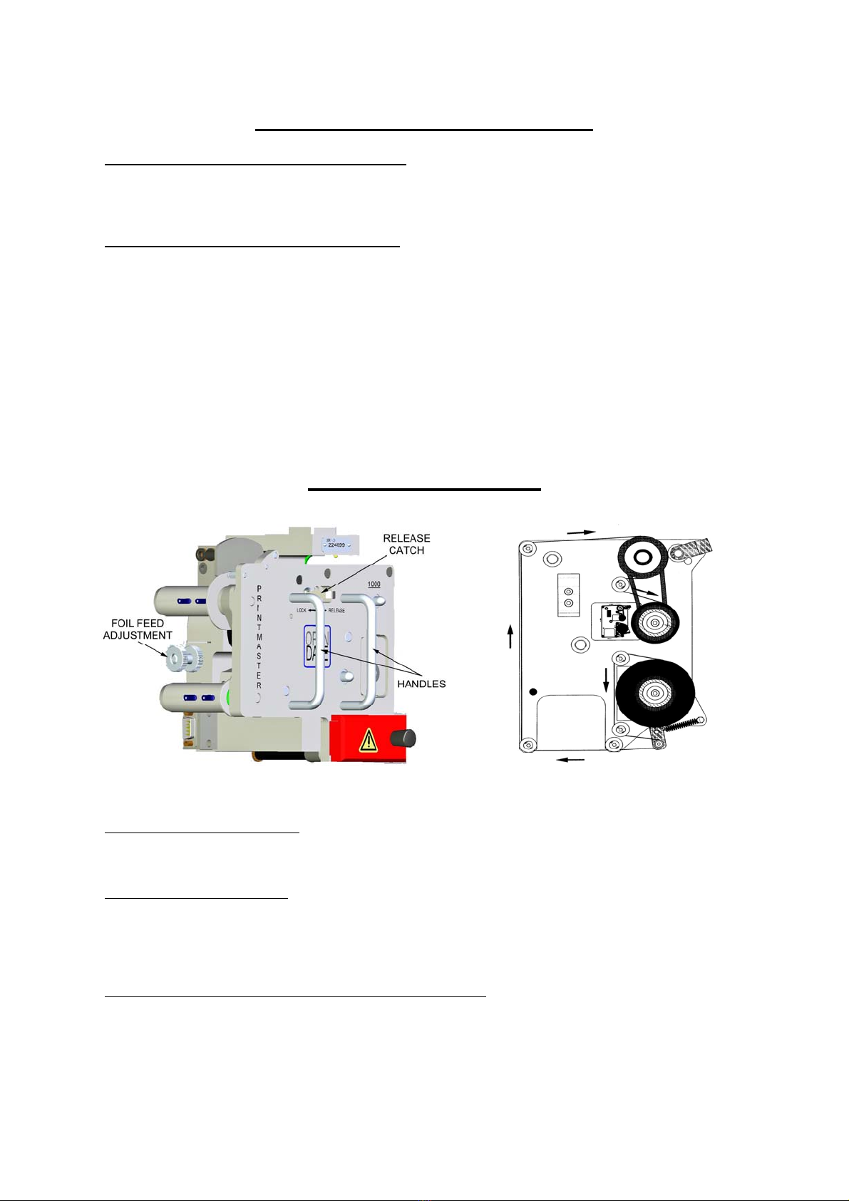
4. Never operate the printer unless it is installed in the mounting frame supplied. When installed
correctly the gap between the printer and print base should not be greater than 4mm (see
page 35).
5. Do not expose any part of the product to liquids or vapours including pressure washing or
steam cleaning.
6. Do not place the product on an unstable stand, table or machine. It may fall causing serious
damage and/or injury.
7. Never insert objects through apertures in the product as they may touch dangerous voltages
or short circuit parts that could result in fire or electric shock.
8. The product must be operated from the type of electrical supply shown on the product identifi-
cation label at the rear of the printer controller (see page 7).
9. The controller to printer cable must only be connected to an Open Date printer. It is not a sig-
nal or data cable. Connecting the cable to anything other than the specified printer may risk
electric shock or damage.
10. To ensure proper earthing the connecting cable from the controller must be fitted securely to
the printer by tightening the two retaining screws on the connector body.
11. The controller has a standard IEC C14 mains connector. A C13 (supplied) or C15 terminated
cable must be used to connect mains power.
12. The mains supply to the controller must be protected by a 5 amp fuse.
13. All cabling must be routed to avoid damage that may cause failure or risk of electric shock.
14. The product is not user serviceable. Opening or removing covers exposes persons to danger-
ous voltages, major burns and other risks. Refer all servicing to qualified personnel.
15. Do not use to use the product in areas where explosive gases or substances are present.
16. In use type-holders become hot enough to cause serious burns (<240°C). Never touch metal
parts of a type holder. Handle type-holders only by their insulated plastic handles. Never as-
sume a type holder is cold.
17. Adjust only those controls and settings covered by these instructions. Improper adjustment
may result in damage needing qualified technicians to resume normal operation.
18. Disconnect the product from the electrical and air supplies and refer to qualified personnel un-
der the following conditions:
If the cabling or connectors are damaged.
If the air pipes are damaged or leaking.
If any part of it has been exposed to liquid.
If the product does not operate normally.
If in doubt contact the manufacturer or authorised agent before proceeding with installa-
tion, operation or servicing.

Printmaster-Digi60 17/04/14
Digi-60 Controller Operating Instructions
Temperature button
To adjust the temperature setting, press and hold down the temperature button
and use the up/down arrow buttons to the left of the display to increase or
decrease the set point. (Required Temperature)
Set point range:- Minimum 70ºC (158ºF), Maximum 240ºC (464ºF).
Note! When selecting operating Modes 1, 3 or 5, the printer will not operate on the
external trigger until the temperature has reached the pre-programmed set point.
(see page 13 for ranges of the mode settings etc.)
In normal operation the temperature will fluctuate by up to ±4ºc from the set point.
Print dwell button
To adjust the print dwell setting, press and hold down the print dwell button and
use the up/down arrow buttons to the left of the display to increase or decrease.
This adjustment controls the time the type/die face is in contact with the substrate.
Higher numbers indicate longer dwell times.
Range: 10mS to 2000mS. (0.01 – 2.0 Seconds)
Print switch
Switches the print signal between ON and OFF LINE.
ON LINE; Green LED lit. The printer accepts external trigger signals
(automatic print cycle). The test button does not operate.
OFF LINE; Green LED not lit. The printer does not accept external trigger
signals, The test button operates the printer.
Note! Fault warnings automatically take the printer OFF LINE. When faults are
cleared the printer can resume ON LINE status automatically or require a manual
reset using the print switch. Refer to page 15 “Settings for ON LINE options” to use
this feature.
Test Button.
Manually triggers the printer when OFF LINE. (Green LED is not lit).
Note! The test button is disabled when the printer is ON LINE
Fault warnings - Red LEDs
Red LEDs indicate the fault conditions shown below. The printer goes OFF LINE when a fault is
detected.
(Refer to pages 22 & 23 for system faults)
Page 5
Air pressure Heater Foil Thermistor Door

Printmaster-Digi60 17/04/14
Page 6
Digi-60 Front Panel Layout
SET TEMP.
SET DWELL TEST PRINT
ON/OFF LINE
VALUE
UP/DOWN
DOOR OPEN
AIR PRESSURE WARNING
THERMISTOR FAULT
ON LINE
FOIL FAULT / E.O.F.
HEATER FAULT
TEMP/DWELL VALUE

Printmaster-Digi60 17/04/14
Page 7Page 7
Digi-60 Controller Rear Panel Layout
POWER SWITCH
MAINS INLET
CONNECTOR USER CABLE
ENTRY
PRINTER CABLE
OUTLET
For clarity cabling is not shown.
PRODUCT IDENTIFICATION LABEL
Showing model number, serial number and
mains supply requirements for the controller

Printmaster-Digi60 17/04/14
Operating Instructions - Printer
MAGAZINE REMOVAL (see Diagram A. below)
To remove the foil magazine, slide the black catch, hold in place and withdraw the magazine using
the black handle. If the printer is on-line (Print LED on) the alarm will sound. Press the PRINT switch
to silence this.
FOIL THREADING (refer to Diagram B. below)
1. Fit an empty foil core onto the rewind mandrel.
2. Disengage the pinch drive roller.
3. Remove label from a new roll of foil.
4. Fit new roll of foil onto take-off mandrel (note unwind direction as shown on threading
diagram).
5. Thread foil around all rollers as shown on threading diagram. Note, the gloss side of the foil
should face inwards throughout the foil path.
6. Attach end of foil to empty core on rewind mandrel, gloss side facing inwards.
7. Wind foil on a few turn to track and tension it.
8. Engage pinch drive roller.
Foil Loading Diagram
Page 8
RE-FITTING FOIL MAGAZINE
Hold the magazine by the handle, slide it onto the locating pins and push to lock in place. Press the
PRINT switch on the control unit if the printer is to be put on-line.
FITTING TYPE/DIE HOLDER
NEVER ASSUME THAT A TYPE/DIE HOLDER IS COLD.
Only pick up the type/die holder by its handle. Ensure that the face of the magnetic catch is clean,
remove the foil magazine as detailed above, align the type/die holder within the two side locators and
slide in until the magnet catches on the keep plate. Re-fit the foil magazine.
FOIL FEED ADJUSTING SCREW (refer to Diagram A. above)
This adjusts the amount of foil used per print. Winding the adjusting screw in reduces the foil pull and
vice versa. Ensure that the locking nut is fully tightened after adjustment. A gap of 1 to 2mm is
recommended between each portion of used foil.
Diagram A. Diagram B.

Printmaster-Digi60 17/04/14
INITIAL SETTING PROCEDURE
1. Ensure that printing foil and substrate are compatible. If in doubt, contact foil supplier for
assistance.
2. Remove Type Holder from printhead.
3. Ensure that rubber print base is clean, undamaged and securely retained in position
under printer.
4. Set air pressure regulator. 4 to 7 Bar is recommended (60 to 100 PSI).
5. Switch controller on.
6. Set print dwell time to 120 milli-seconds and temperature to 125ºc (257ºF). 3 to 4
minutes should be allowed for printer to reach working temperature.
7. Load type or die into holder, centrally if possible and fasten securely. Make sure that
typeface is clean.
8. Load type/die holder into printer and close door. If cold, allow 3 to 4 minutes for holder
to heat up before printing.
9. Ensure the printer is off line
10. Place a sample of substrate material under printer and press TEST button. Inspect
resulting print.
11. Adjust print levelling screws until a light, uniform print impression is achieved. Lock
levelling screws.
12. Adjust foil metering screw for economic foil use as detailed previously and tighten
thumb nut.
13. Switch the printer to on line for automatic operation.
PRINT ORIENTATION
To rotate the printer and therefore turn the overprint through 90 degrees, remove the foil
magazine (if applicable), unscrew the clamping handle until the location square on top of
the printhead is clear of the top rails, turn it to the required position, tighten the clamping
handle and replace the magazine.
TEMPERATURE ADJUSTMENT (refer to page 5)
Normal setting is about 125ºc. (257ºF).
Should the print not fully adhere to the substrate then a higher setting may be used.
Small, fine detail print generally requires a lower temperature.
Thermoplastic films and especially polyethylene generally require a lower
temperature.
Aluminium foils, paper and untreated polyester require a higher temperature.
See pages 13 & 20 for temperature mode & calibration
PRINT DWELL ADJUSTMENT (refer to page 5)
Normal setting is about 120 milli-seconds.
Generally, the larger the print, the higher the setting.
Should the print not adhere fully to the substrate, a higher setting may be used.
Remember, the printhead can only operate during the stationary cycle of the web, if
the print time is longer than this the web may break.
Should the dwell time have to be decreased to accommodate higher production
speeds, it may be necessary to compensate by increasing the temperature setting.
Page 9

Printmaster-Digi60 17/04/14
Air Flow Controls
The airflow restrictors are usually attached to the solenoid valve exhaust ports. They work by
regulating the speed at which air is exhausted from the air cylinder.
Turning the adjusting screws will alter the exhaust airflow and consequently the print ram velocity, it
will also affect noise levels.
Increasing the exhaust airflow from the forward stroke of the print ram will increase the print
pressure. Decreasing the exhaust airflow will reduce print pressure and the resulting print will be
lighter.
The drive for the printing foil is taken from the return stroke of the print ram. Increasing the exhaust
airflow will speed up the foil feed. To ensure efficient foil feeding, the return stroke should be as
gentle as possible.
For higher speed operation, the exhaust airflow from both the forward and return strokes will have to
be increased.
Note, it is very important that the print ram returns fully before the next print cycle
commences.
Solenoid Valve Details
Refer to the diagram on page 11 for correct orientation of black and red air pipes to printer. Reversed
printer air connections will force the print ram fully down (print position) instead of fully up (home
position)
Air flow restrictor
for print stroke
PORT 2
Black 6 mm air pipe to printer
Page 10
PORT 4
Red 6 mm air pipe to printer
Air flow restrictor
For return stroke
PORT 1
Incoming air supply - 6mm tube.
4 - 7bar (60-100psi)
Clean, dry air
Electrical connector.
Refer to connection
details on page 17

Printmaster-Digi60 17/04/14
PRINTMASTER CONNECTION DETAILS
(R/H VERSION SHOWN)
Page 11
AIR SUPPLY. 6mm DIA
NYLON TUBING.
4 - 7 BAR (60 - 100 psi)
CLEAN, DRY AIR.
5mm Black Nylon Tubing
5mm Red Nylon Tubing
Note
In order to achieve optimum speed
performance, the solenoid valve
assembly should be positioned very close
to the printer so that the 6mm air pipes
can be as short as possible.
AIR SUPPLY. 6mm DIA
NYLON TUBING.
4 - 7 BAR (60 - 100 psi)
CLEAN, DRY AIR.

Printmaster-Digi60 17/04/14
SETTING UP DIGI-60 CONTROLLER
Page 12
See page 14
See page 13
See page 15

Printmaster-Digi60 17/04/14
DIGI-60 MODE SETTINGS FOR TEMPERATURE
TOLERANCE RANGES
Page 13

Printmaster-Digi60 17/04/14
DIGI-60 DIP SWITCH SETTINGS
Page 14

Printmaster-Digi60 17/04/14
Thermistor & ON-LINE DIP Switch Settings (SW1)
Page 15

Printmaster-Digi60 17/04/14
Digi-60 Basic Connections
(See page 17 for details)
Page 16
KEY TO COLOUR CODES:
BK = black, BN = brown, RE = red, YE = yellow, GN = green, BU = blue,
PU = purple, WH = white, PK= pink, SC = screen or braid of cable
IMPORTANT—TO AVOID SHOCK RISK
THE PRINTER IS EARTHED VIA THE CONNECTOR AND BRAIDED SCREEN OF THE
CONTROLLER CABLE. THE CONNECTOR RETAINING SCREWS MUST BE FULLY TIGHTENED
FOR PROPER EARTHING. THE PRINTER MUST NOT BE USED IF THE CONNECTOR OR
CABLE IS DAMAGED OR THE SCREEN IS NOT ATTACHED TO THE CONNECTOR BODY

Printmaster-Digi60 17/04/14
Page 17
Digi-60 Connection Details
Page 17
PRINT TRIG PRINTER TRIGGER SIGNAL - grey 2 core screened cable.
See page 14 print trigger selection for details of input print signals.
P+ Red External trigger input + volts connection.
P- Black/Blue External trigger input - volts connection.
AIR VALVE PRINTER AIR SOLENOID VALVE - black 2 core unscreened cable.
N.B. To avoid internal damage do not short these wires or allow them to be grounded. Be
sure to use the correct terminals on the valve connector for +ive and -ive wires.
S+ Red Air solenoid valve output +ive connection. Use terminal 1 on the connector
S- Blue Air solenoid valve output -ive connection. Use terminal 2 on the connector
PRINTER Multicore screened cable to D9 socket.
N.B. Shock risk; mains voltage. See safety warnings on pages 4 and16.
C/U Colour Function D Connector
TH Yellow Thermistor connection. Pin 1
TH Green Thermistor connection. Pin 2
HE Red Heater LIVE connection. (230Vac!) Pin 3
HE Blue Heater NEUTRAL connection. (230Vac!) Pin 4
D1 Brown Door switch and foil sensor 0V. Pin 5
D2 Purple Door switch state. Pin 6
PM White Foil sensor. Printmaster only. Pin 7
F1 Black Foil sensor output. Pin 8
F2 Pink Foil sensor +24V. Pin 9
Screen Protective Earth. Connector body
MAINS ELECTRICITY SUPPLY
A standard IEC C14 connector is fitted to the rear of the controller
This accepts the IEC C13 or C15 (hot condition) 3 pin connector (Commonly called a ‘Kettle’ lead)
MAINS SAFETY - To avoid shock or fire hazards:
The incoming mains supply must be protected by a 5A fuse.
The controller must be earthed via the mains connector.
Refer to page 4 for detailed safety information.
For PRINT and FAULT relay connections refer to page 18
For AIR SW optional low air pressure warning refer to page 19

Printmaster-Digi60 17/04/14
Page 18
DIGI-60 Fault and Print Relay Connections
There are two relays for indicating printer system status to external equipment. The relays may be
used independently or linked in series to obtain full warning status on a single connection.
Each relay has COM, N/C and N/O contacts rated 24V @ 1A maximum
Using the N/O contact of each relay gives a positive indication only when the printer is in normal/
ready condition and the control voltage is present. (Fail safe operation)
FAULT RELAY Changes state when a fault is detected. (door open, foil fail, heater fault,
thermistor fault or low air pressure).
PRINT RELAY Changes state when the printer is ON or OFF line.
Page 18
Wiring for Independent Fault/Print Indications
Wiring for Combined Fault/Print Indications

Printmaster-Digi60 17/04/14
Page 19
Digi-60 Low Air Pressure Warning (optional)
The printer will not operate without a compressed air supply. An air pressure sensor switch (optional,
not supplied) may be fitted to provide a low air fault condition to the Digi-60 controller and operate the
fault relay.
The switch contacts should be closed when the air pressure is OK.
The switch contacts should open when the air pressure is low.
Adjust the switching pressure to suit the application
Connect the switch as shown in the diagram below. The low air pressure feature must be activated
by changing a DIP switch on SW2. Refer to page 12 for the location of SW2 on the Digi-60 controller
and page 14 “Low air configuration SW2” for switch settings.
Page 19
Wiring for Low Air Pressure Warning

Printmaster-Digi60 17/04/14
DIGI-60 CALIBRATION METHOD
Note: Calibration Temperature Range = 70ºC to 220ºC (158ºF to 428ºF)
The control unit is factory calibrated at 130ºC, and is set up in “MODE 1”supplied as
standard. See page 13 for a list of the different modes available.
Unless you are running temperatures outside the range 70ºC to 180ºC (158ºF to 356ºF), the
default calibration should not be altered.
Fitting of an alternative thermistor (THE 515002) will require (SW1) position to be altered
(See page 15), again this will be accurate to plus or minus 7°C. If accurate temperatures
are needed, you should recalibrate to suit the individual thermistor fitted.
For normal running temperatures above 180°C you should recalibrate at 200°C.
External Calibration Method
Switch the Digi60 unit on and adjust the temperature setting to 130ºc or 266ºF.
Leave on for 10 to 15 minutes, allowing the temperature to stabilise.
Measure the temperature at the type face using a temperature probe.
Allow the temperature probe to stabilise before noting the reading.
Adjust the Digi60’s set point to match the temperature probe reading.
Press the both the up and down arrow keys at the same time then press the print switch.
The controller is now calibrated.
Page 20
This manual suits for next models
2
Table of contents
Other Open Date Printer manuals