Opitec 110.372 User manual

1
E110732#2
110.372
F M Radio
Necessary Tools:
Fretsaw
Ruler,pencil
Sandpaper
Wood glue
All purpose glue
Drill ø4; 4,5,10 mm
Soldering iron, solder
Wire strippers
Side cutters
File
Scissors
Acrylic paint
2-component glue
or glue gun
Please Note
The OPITEC range of projects is not intended as play
toys for young children.They are teaching aids for
young people learning the skills of Craft, Design and
Technolo- gy.These projects should only be underta-
ken and tested with the guidance of a fully qualified
adult. The finished projects are not suitable to give to
children under 3 years old. Some parts can be swallo-
wed. Dan- ger of suffocation!

2E110732#1
210
300
300
210
INSTRUCTIONS
PARTS LIST
Code Quantity Size (mm) Description Teile-Nr.
PLywood 1 300x210x5 Housing 1
Wooden strip 2 200x40x15 Base plate 2
Modelling plywood 1 300x60x1,5 Top (Version 1) 3
Wooden wheel 2 ø 30 knob 4
Jute material 1 200x145 Loudspeaker cover 5
Loudspeaker 1 ø57 Loudspeaker cover 6
Plastic tube 1 ø4/3 Insulation 7
IC holder 8leg 1 8
Cable 1 2000 Wire aerial 9
IC TDA 7021T 1 Receiver 10
Circuit board for FM-Radio 1 11
IC TDA 7052A 1 NF-Amplier 12
Potentiometer 1MOhm 1 6 13
Capacitor 820 pF 821 1 C4 14
Capacitor 3,3 nF 3n3 2 C6/7 15
Capacitor 1,0 μF 105 1 C10 16
Capacitor 0,47 μF 474 1 C9 17
Capicitor 4,7 nF 4n7/472 1 C5 18
Capacitor 0,1 μF 104 3 C2 19
Capcitor 0,01 μF 103 1 C1 20
Capacitor 33pF 33 1 C3 21
Capacitor 220 μF 1 Capacitor, C8 22
Micro switch 1 19x6 Switch 23
Flat connector 2 6,3 Battery connection 24
Cable red 1 500 Cable 25
Silver wire 1 500x0,6 Coil 26
Zylinderkopfschraube 1 30x3 Sendereinstellung 27
Nuts 1 M3 Mutter 28
General :
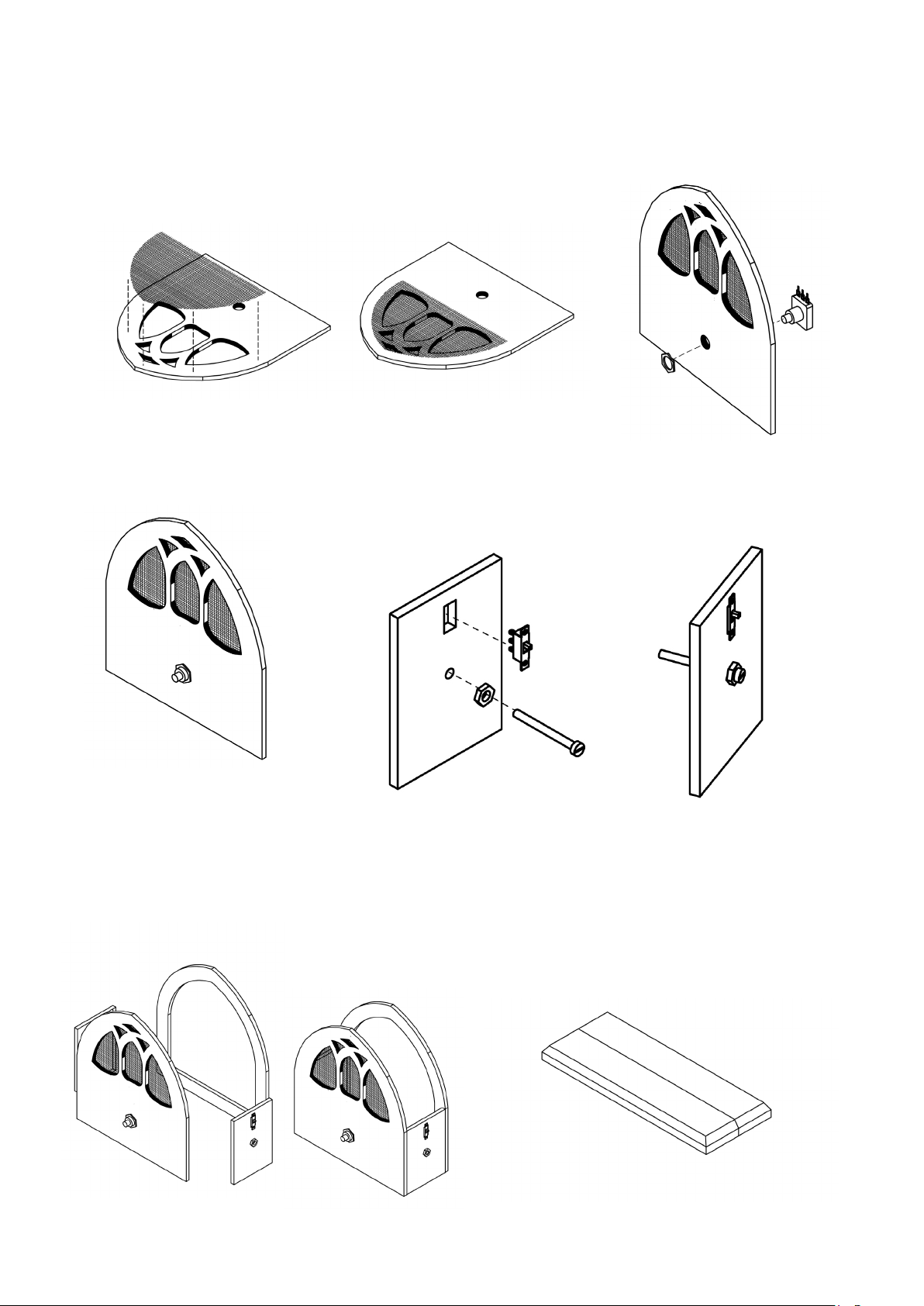
The casing of FM radio is shown in two versions. There are plans for both versions. In the instructions only one variati-
on is described the other version is similar . Both variations are are shown with exploded drawings. (Page 7)
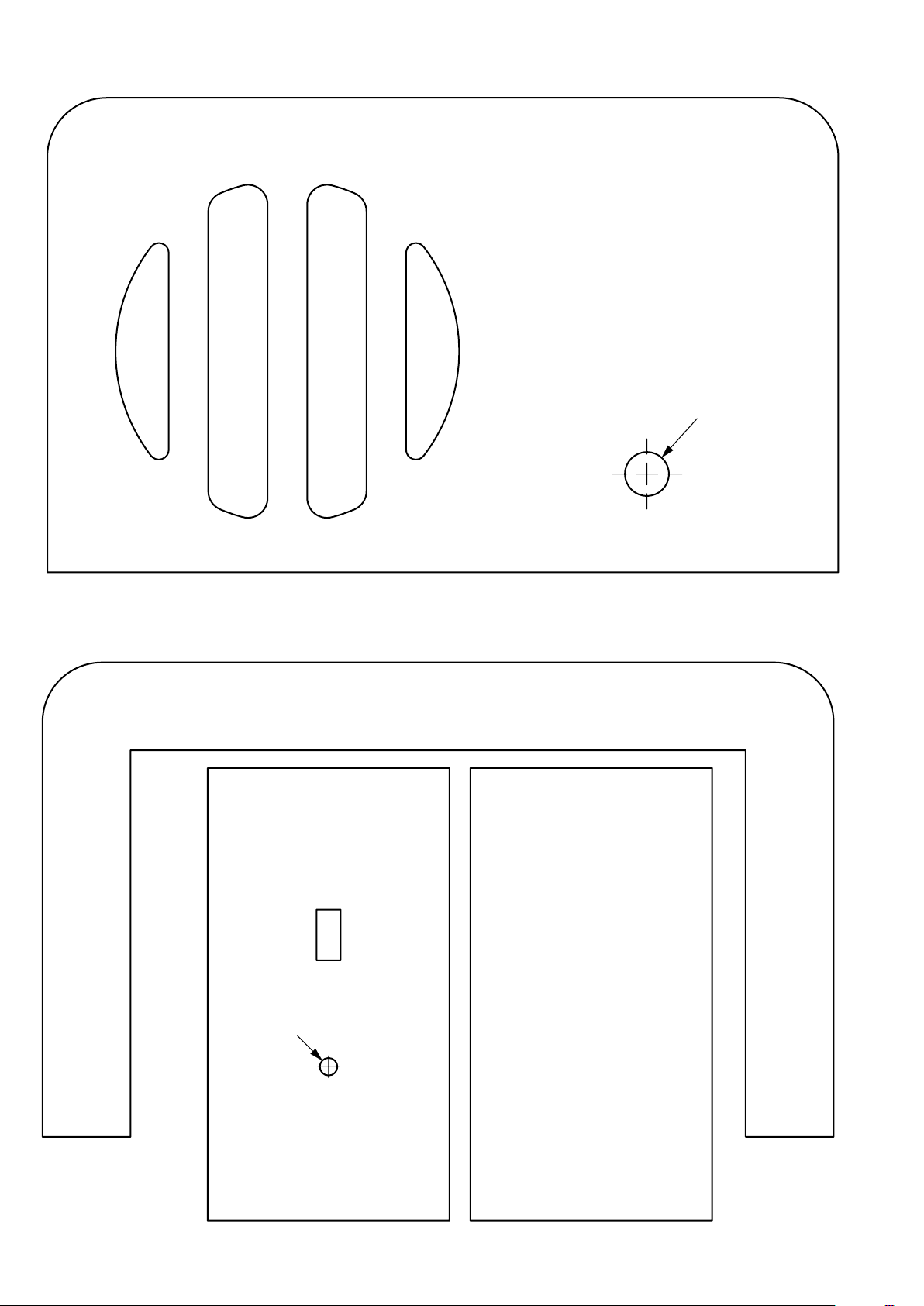
1. Trace or copy the plans for the housing on to
the plywood sheet (1) according to the plan
(see dia 1 and page 6). Saw out the parts with a
fretsaw and sand the edges.
Also saw out any internal shapes and drill the
holes as shown.
Dia.1

3
E110732#2
INSTRUCTIONS
2. Cut the jute (5) as shown so that it
covers the cut out on the front of the
housing.
3. Use PVA wood glue to ensure that
the jute lays at over the shapes
5. Shorten the end of the potentiome-
ter (15) with a ne bladed saw to
10mm and insert it into the hole in
the front as shown
6. Screw the nut on the front
and tighten.
7. Take the side part with the cut out for the switch (22) Insert the switch
and glue it in place. Add the nut (28) outside and glue it over the 4mm hole
or instant glue. Insert the screw (27) in the nut . No glue should creep on to the
thread !
8. Glue the parts together as shown and leave them to dry
well
9. Shorten the wooden strips (2) to 170 mm long . ( Version
2 do not shorten!) The strips must be chamfered at 45
degrees (see dia.). on three sides. Glue the two strips
together on the non chamfered edges and leave to dry.

4E110732#1
INSTRUCTIONS
10. Glue the housing centrally on the
pre-glued base
11. Cut two 130mm long pieces from
the modelling plywood (3) and glue
them on the housing as shown
12. Take the wheel (4) and on non
milled side drill a blind hole 6mm
dia 5mm deep
14. Take the second wooden wheel
(4) on opposte sto the milled side
drill a blind hole ø 5,5 mm by 5mm
deep. Glue the head of the machine
screw (27) in the hole with hot glue
15. Take the wooden wheel with the
machine screw (4/27) and screw it
into the nut on the side (28)
13. Set the wooden wheel (4) on the
potentiometer (15) and glue in place
( Hot glue gun ) See diagram !
Note:
In the second version glue the 2 supports 55x10x5 for the top ( see diagram ) Once its all dry the top corners can be round-
ed
Glue in support Round o the corners
ø5,5
ø6
16. Place the plastic (7) tube from the inside in the hole of the nut (28) use instant glue or hot glue gun. To x the M3 machine
screw( 27) outside use a nut.
Note . no glue should creep on to the screw thread !
17. The nished housing is ready for painting . We recommend using acrylic paints or varnish!

5
E110732#2
C1C2C3
C2
C4
L1
C6 +
+
16 1
6
L+
2 7
4
98
1 8
C8
-C10
L-
A
C2
C5
C9
3
45
-IC 1
C7
-
4,5 V
C1C2C3
C2
C4
L1
C6 +
+
16 1
6
L+
2 7
4
98
1 8
C8
-C10
L-
A
C2
C5
C9
3
45
-IC 1
C7
-
4,5 V
100 nF
33 pF
TDA 7021T
2
10 nF
14
1
3,3 nF
12
15
220 uF
3,3 nF
820 pF
8
100 nF
457
6
4,5 V
11 10
4,7 nF
37052A 5
100 nF
12
TDA
6
3
8
4
1,0uF
470 nF
1MOhm
1MOhm (13)
Lautsprecher (6)
Switch (23)
3,3 nF
(15)
0,47 μF (17)
4,7nF (18)
220μF (22)
1,0μF (16)
0,1μF (19)
820pF (14)
3,3nF (15)
Silver wire coil (26)
0,01μF (20)
0,1μF (19)
Circuit (top view):
Cicuit board from underneath
19. Solder on the components as shown and insert the board into
the housing
IC TDA 7021 T
already soldered!
IC TDA
7052A
(12)
INSTRUCTIONS
Soldering the components on the circuit board:
18. Use a 4mm drill as a former to wind 6 turns of siver wire close together ( See diagram.) Bend the end of the colil as shown
Pull the ends of coil carefully apart so that it can be soldered on the circuit board as shown. Place it so that the coil does not
lay on the boards but a litte above. Solder in place. Trim the ends under the board
Later place of the plastic tube (7)
Circuit board
Placing and soldering the components on the circuit board
The circuit board has two distinct sides : The top is drilled and printed - the underneath shows all the tracks where the com-
ponents are soldered.
The IC holder (8) as shown on the top circuit board diagram, the holder
is placed on the top and soldered underneath NOTE the holder has a notch at one end this must be inserted as shown . This
ensures that the IC when inserted is the correct way around.
- The amplier IC (12) is the last component to be inserted otherwise it could be damaged by soldering.
- Insert the capcaitors C1, C2, C3, C4, C5, C6, C7, C9, C10 from the top and lightly bend the legs ten solder them to the un-
derneath of the board
Check them once once that they are in the corret place. Finally trim o the component legs protruding under the board with
side cutters
Then add the eletrolyte capacitors C8, 220 μF (22) The dierence with these CAPACITORS is that they have a POLARITY and
must be inserted the correct way around. The MINUS of the capacitor is marked on the circuit board.
33pF (21)
Silver wire (26)
4mm-drill
150mm (red)
150mm (schwarz)
100mm (black)
150mm (black)
150mm
(rot)
Schematic diagram

6E110732#1
- Take the cable from the loudspeakers (each ca. 150mm red + black) stripthe insulation from the ends. Twist the inners to-
gether and tin them with solder. The red cable from the plus on the loudspeaker is connected and soldered to the Red L+ on
the board. The black cable is soldered to the L-minus on the board.
- Trim Ca. 150mm from the black cable and remove the insulation from both ends. Solder it to the middle connection on the
potentiometer (13) The other end is soldered to the Minus on the board. Cut another piece, from the black cable ca. 100mm
long, strip and tin the ends. Solder it to an outer connection on the potentiometer(13) and the other end to the middle
connection on the switch (23). Take about 150 from the red cable, strip the insulation from the ends. an solder it to an outer
connection on the potentiometer (13) Connect the other end to the circuit board. ( unmarked connection ). Solder the minus
cable-see diagram of balck cable 150mm to the outer connection on the switch (28) Solder ca. 150mm long piece of cable
,and connect it to the +- on the circuit board. Srtip and tin the the ends of the remaining black cable and solder t as an aerial
to the board (A).
- Use the at conncters (27) on the battery connection wires and solder them to the plus -minus on the circuit board.
- The following checks should be made to avoid any damage to the components on the board.
Ensure that there is no excess solder making connections where theshould not be ( See circuit diagram )
Make sure that all the components are in their correct place ( see circuit diagram ) Make sure that their values are correct ?
- Erst wenn diese Arbeit durchgeführt ist kann der IC (12) seitenrichtig in die IC-Fassung eingesetzt werden. Dabei ist darauf
zu achten, dass alle Beine in der Fassung stecken.
- Adjust the potentiometer to the middle position (mddle volume.
- Now connect a new 4.5volt battery. You will either hear a nose or receive a program .
- If this doesn#t work go through all te checks as above once more .
- If you hear a noise, you can widen the coil a little until you recive a staion. At least you can see that it is working corretly or
not
To receive dirent stations is hard and patient work to adjust, you do this by screwing in the centre of the coil. The plastic
tube stops the direct contact with the coil
Fianl assembly
- Mount and glue the loudspeaker to the wooden frame behind the jute materail.Use a hotglue gun or 2 part glue.
- To t the crcuit in the housing : Slide the coil over the platic tube. Then turn the circuit board so thta it lies on the front and
side part of the hosing
Testthe radio works once more. Glue the circuit board in the front part of the housing
INSTRUCTIONS

7
E110732#2
BAUANLEITUNG
Expoded diagram
Variantion 1
Exploded diagram
Variantion 2

8E110732#1

9
E110732#2
Ø 10
Pattern variation 1
Sale 1:1
Front
INSTRUCTIONS

10 E110732#1
Ø 10
Ø 4
INSTRUCTIONS
Pattern Variation 2
Scale 1:1
Back part
Front
Side part
Side part

11
E110732#2
Ø 4
Pattern Variation 1
Scale 1:1
Back part
INSTRUCTIONS
Side part Side part

12 E110732#1
INSTRUCTIONS
Cover
Support Support
Pattern Variation 2
Scale 1:1

13
E110732#2
210
300
300
210
INSTRUCTIONS
Cover
Side
Back part
Front
Side part
back
Front
Cutting plan Varaition 1+2
Table of contents