Shenzhen Friendcom Technology Development Co., Ltd.
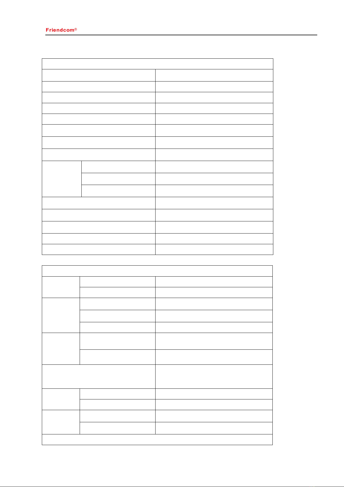
Table 1
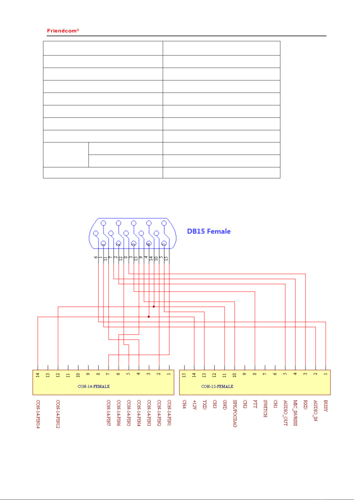
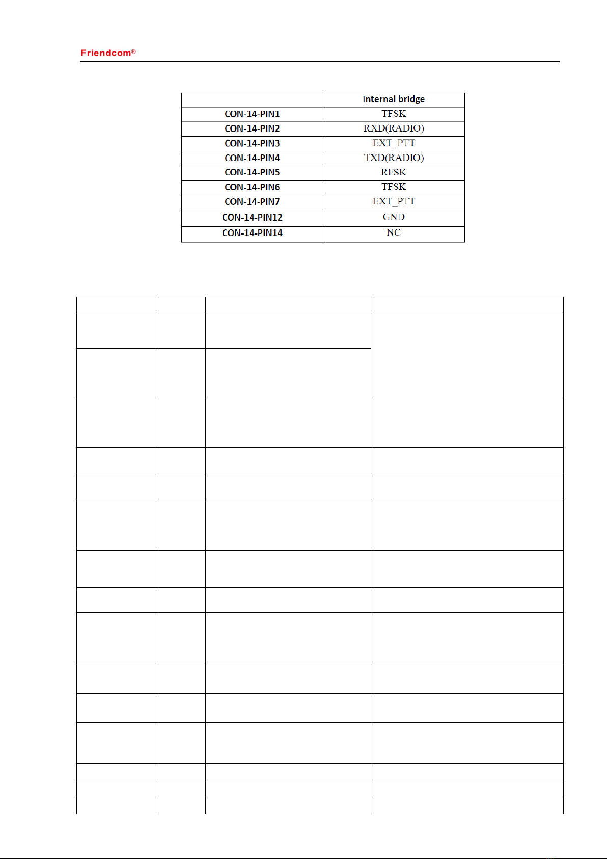
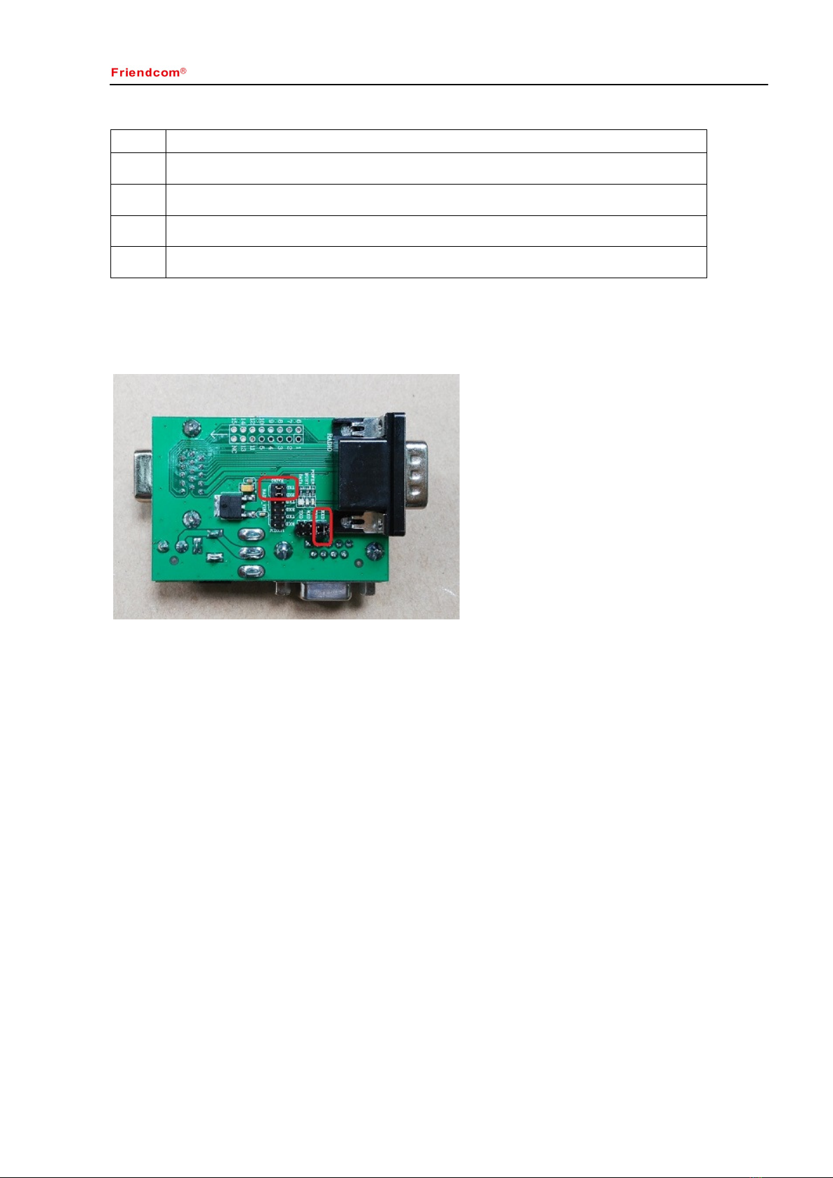
3.1 Pin Assignment
As to FC-302V radio,the pin assignment is shownin Table 2.
Table 2
PinName Pin No.Description Remark
AUDIO_IN
(MOD IN)1Audio input. 3KHz LPF,
Modulation sensitivity is 100mV. AUDIO_IN is effective only when PIN
7(MIC) is vacant or with +5V high level.
3KHz LPF filter existed in audio channel.
AUDIO_OUT
(AFOUT)2
Audio output, 3Khz LPF. Output level
at 60% frequency deviation is
250±50mV. This line has an internal
-up resistor to +5V.
PTT3
TX control, active low, only when PTT
is active AUDIO_IN and MIC IN are
effective. This line has an internal pull-
up to 5V.
B+
(9.5~16V DC) 4 Positive pole input from DC power,
nominal +12V.
PROG
(DATA OUT) 5 Programming data output, 5V TTL
BUSY 6
Logical level output to indicate whether
there is a carrier or not. Low lever =
carrier,highlevel=no carrier. This line
has a pull-up to +5V.
MIC IN/RSSI 7
MIC IN: Microphone input.
RSSI: To detect the air signal strength.
Jumper selectable.
Can directly connect to electrets MIC, the DC
voltage of this pin should lower than 3.5V,
then MIC transmission can be activated.
PROG
(DATA IN) 8 Programming data input, 5V TTL
SPK/
POCSAG 9
SPK: Audio output from the audio
amplifier, @ 8Ω.
POCSAG: Totransmit POCSAG code.
Jumper selectable.
AUDIO_IN is effective only when PIN
7(MIC) is vacant or with +5V high level.
3KHz LPF filter existed in audio channel.
10
11
12
13
14 Ground
15
6
NC
GND
NC
NC
NC
NC