Opitec 105.026 User manual
Popular Safe manuals by other brands

Euromate
Euromate 406210 Original instructions

SPORTS AFIELD
SPORTS AFIELD PRESERVE SA72-60WD instruction manual

Squire
Squire Stronghold Keysafe Fitting instructions

Phoenix
Phoenix FS0352C Instructions & Guarantee Registration

Hornady
Hornady SnapSafe Trunk Safe II owner's manual

Phoenix
Phoenix KS0030E Series operating instructions

Vaultek
Vaultek 10 Series Quick setup

Arregui
Arregui CLASS operating instructions

Technomax
Technomax Trony Series Instruction handbook

SPORTS AFIELD
SPORTS AFIELD INSTINCT BIOMETRIC Series instruction manual

SPORTS AFIELD
SPORTS AFIELD SA-HD5-BIO instruction manual

Olymp
Olymp GOsafe 110 operating instructions

Phoenix
Phoenix SS0100E Operating Instructions & Guarantee Registration

Ankaro
Ankaro ANK EZ I quick start guide

Honeywell
Honeywell 2077D - 1.21 Cubic Foot Anti-Theft Safe user guide

Beaumont
Beaumont SMART KEYBOX user guide

Phoenix
Phoenix FS1270E Series operating instructions

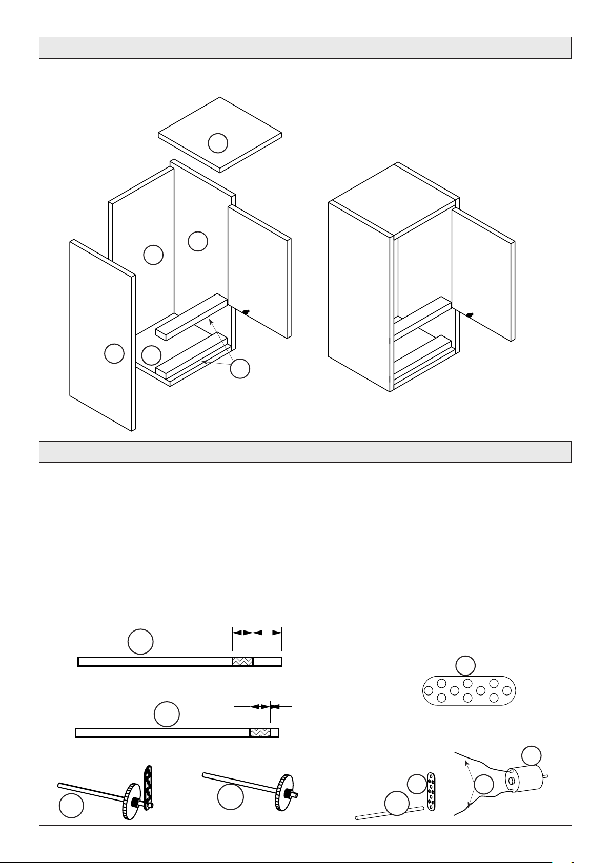
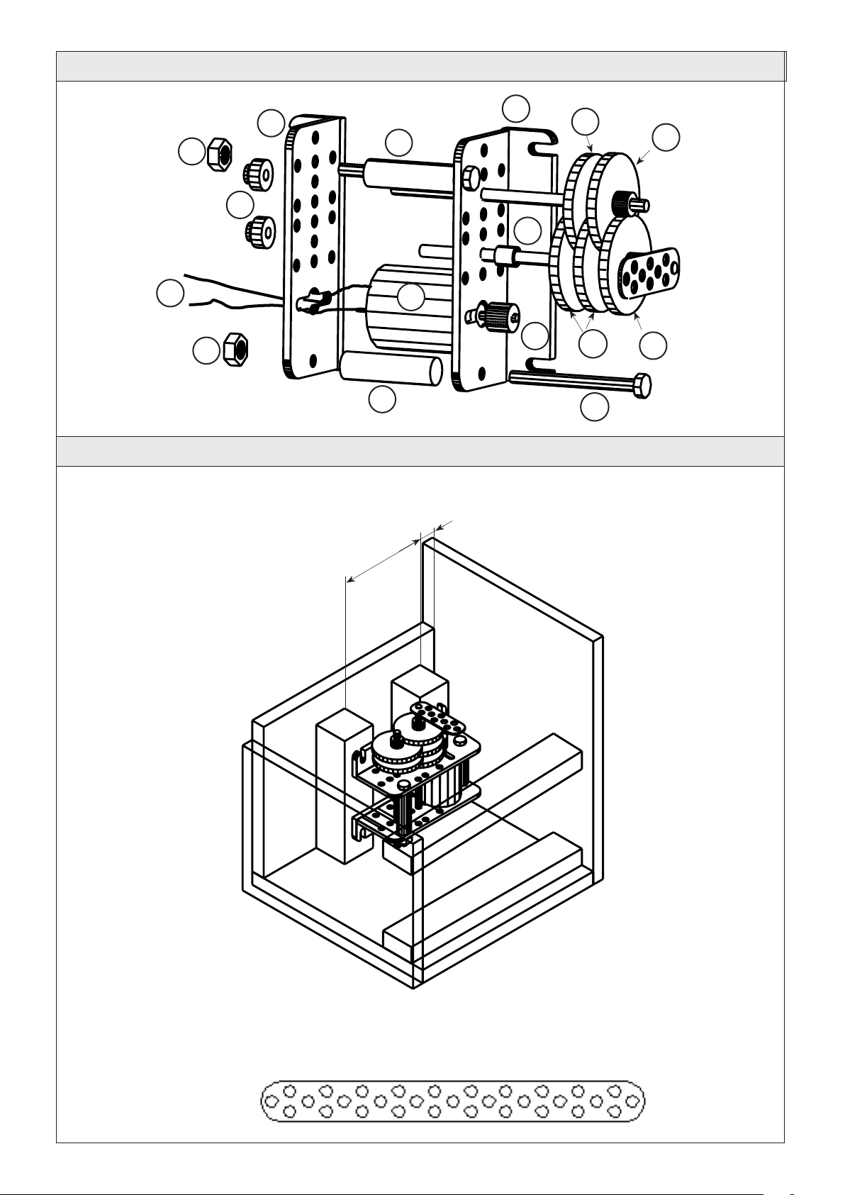
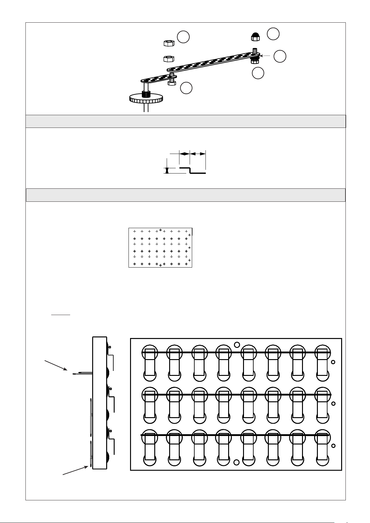
Shure
Shure T-Wall Series Assembly instructions