1
The Contents of Packaging Table of Contents
1. For safe use ...........................................................................2
2. Names of the parts ...............................................................4
3. Measuring principle ............................................................ 10
4. Installation ........................................................................... 11
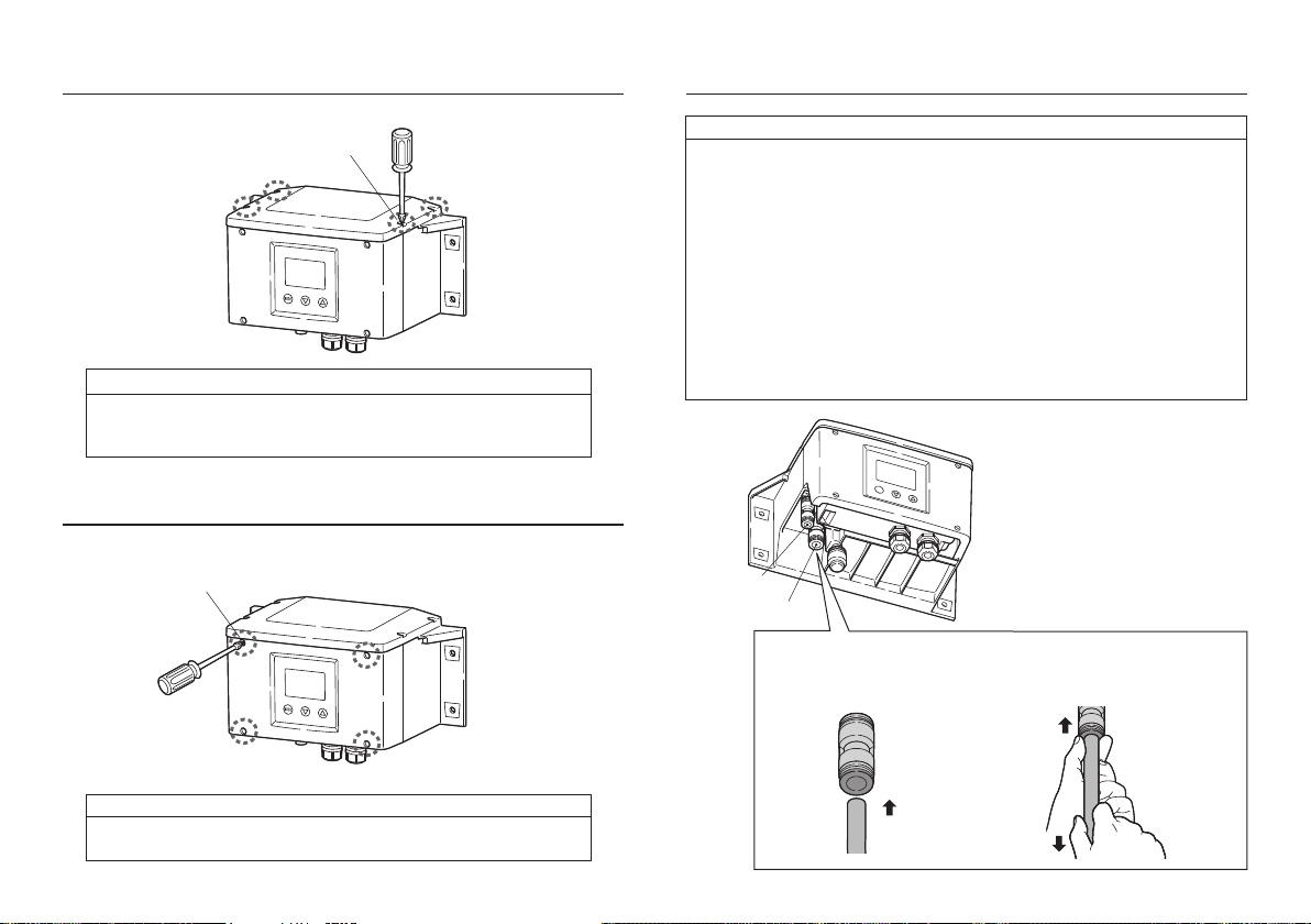
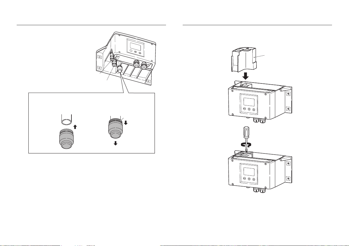
Installing TC-Mi unit ...................................................... 11
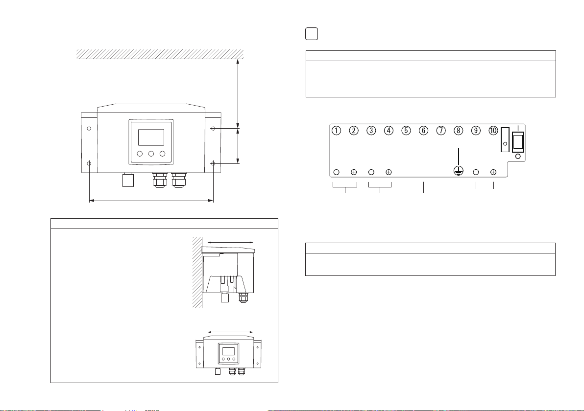
Wiring.............................................................................. 13
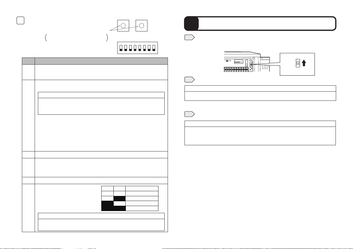
Setting the DIP switch ................................................... 14
5. Operation start .................................................................. 15
6. Operation ........................................................................... 16
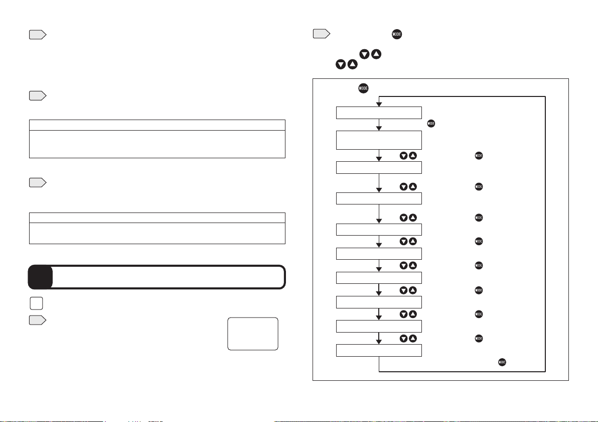
Setting ........................................................................... 16
Output selection ............................................................ 19
Alarm level, Alarm timer ................................................ 20
Signal output response time setting .............................. 21
Noise reduction setting ................................................... 22
Turbidity unit selection ................................................... 23
Offset adjustment ............................................................ 24
LCD contrast adjustment ................................................ 24
Digital communication setting display ........................... 25
7. Troubleshooting .................................................................. 26
8. Maintenance........................................................................ 27
9. Specifications ..................................................................... 29
10. Dimensions ........................................................................ 30
11. Digital communications ...................................................... 31
MODBUS protocol ......................................................... 31
TC-Mi protocol ............................................................... 35
1
2
3
1
2
1
2
3
4
5
6
7
8
9
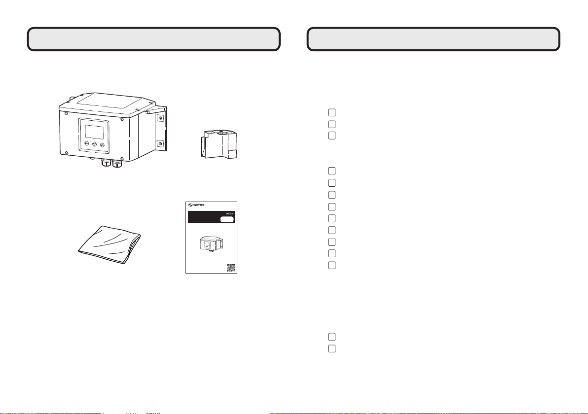
TC-Mi Deaerator
Cleaning paper Instruction Manual
In the unlikely event that there are any missing components or defects, please
contact your dealer.
TC-Mi
Turbidity Checker
Thank you very much for purchasing Turbidity Checker TC-Mi.
All of this instruction manual must be read before operation of the
Turbidity Checker for safe and proper operation.
This instruction manual should be kept for future reference such as
maintenance.
Instruction
Manual
The instruction manual is also available on the following website.
https://navi.optex.net/manual/05297/?lang=en