CIMETRIX TCM-R1 User manual

TCM-R1
Leeb Hardness Tester
User Manual

Preface
Dear users:
Thank you for your purchase of our Leeb Hardness Tester of TCM-R1
Series (it is called Hardness Tester belo ), the Hardness Tester is portable
device, and it is equipped ith printer and soft are for data processing. It is
small in size, light in eight and easy to catch ith. Before using the
Hardness Tester you must read this User’s Manual carefully, hich could help
you use this device correctly and e hope that it could open up to your
satisfaction.
The Hardness Tester confirm to the follo ing specifications:
Technical standards for Leeb Hardness Tester, JB/T 9378-2001
Transformation relation of different hardness scales, ISO 18265: 2003

CONTENTS
1 Structure Feature......................................................................................................................... 3
2 Overview...................................................................................................................................... 7
3 Preparation & Testing................................................................................................................. 12
4 Operation in Details................................................................................................................... 17
5 Servicing & Maintenance........................................................................................................... 2
Malfunction analysis and maintenance......................................................................................28
7 List of components not warranty............................................................................................... 29
8 Instructions for Standard Leeb Hardness Test Specimen............................................................30
Users Notice.................................................................................................................................. 32
1 Structure Feature
1.1The body
Front vie
1.2 Impact device of type D
1. Release button 2.Plug of the impact device 3.Connection cable 4.Loading tube
5.Guide tube 6.Coil unit 7. Impact body 8.Support ring
1.3 Some other types of impact device for purchasing
1.4 Technica Specifications
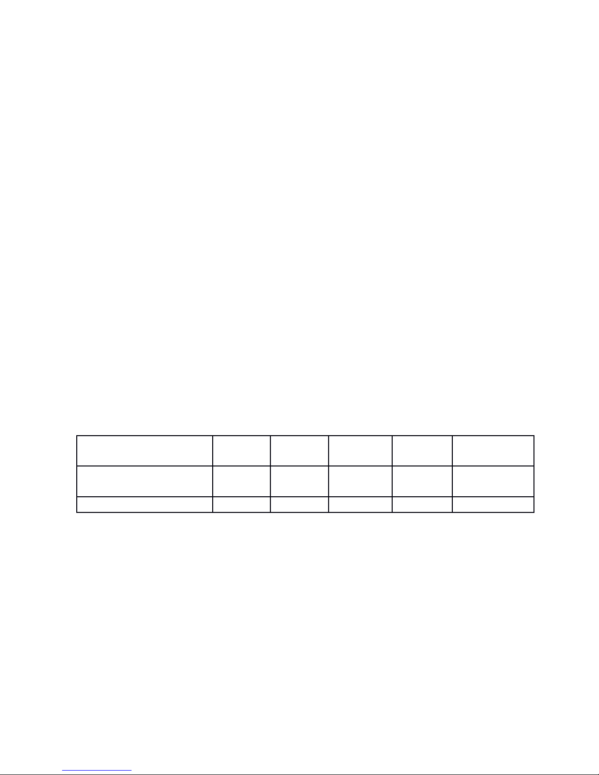
Error and repeatability of displayed value see Table 1.
Table 1
Type of impact device DC(D)/DL D+15 C G E
Impacting energy
Mass of impact body
11mJ
5.5g/7.2g
11mJ
7.8g
2.7mJ
3.0g
90mJ
20.0g
11mJ
5.5g
Test tip hardness: 1600HV 1600HV 1600HV 1600HV 5000HV

Dia. Test tip:
Material of test tip:
3mm
Tungsten
carbide
3mm
Tungsten
carbide
3mm
Tungsten
carbide
5mm
Tungsten
carbide
3mm
synthetic
diamond
Impact device diameter:
Impact device length:
Impact device eight:
20mm
75mm
50g
20mm
162mm
80g
20mm
141mm
75g
30mm
254mm
250g
20mm
155mm
80g
Max. hardness of sample 940HV 940HV 1000HV 650HB 1200HV
Mean roughness value of
sample surface Ra:
1.6μm 1.6μm 0.4μm 6.3μm 1.6μm
Min. eight of sample:
Measure directly
Need support firmly
Need coupling tightly
>5kg
2~5kg
0.05~2kg
>5kg
2~5kg
0.05~2kg
>1.5kg
0.5~1.5kg
0.02~0.5kg
>15kg
5~15kg
0.5~5kg
>5kg
2~5kg
0.05~2kg
Min. thickness of sample
Coupling tightly
Min. layer thickness for
5mm 5mm 1mm 10mm 5mm

surface hardening ≥0.8mm ≥0.8mm ≥0.2mm ≥1.2mm ≥0.8mm
Size of tip indentation
Hardness
300HV
Indentation
diameter
Depth of
indentation
0.54mm
24μm
0.54mm
24μm
0.38mm
12μm
1.03mm
53μm
0.54mm
24μm
Hardness
600HV
Indentation
diameter
Depth of
indentation
0.54mm
17μm
0.54mm
17μm
0.32mm
8μm
0.90mm
41μm
0.54mm
17μm
Hardness
800HV
Indentation
diameter
Depth of
indentation
0.35mm
10μm
0.35mm
10μm
0.35mm
7μm
--
--
0.35mm
10μm
Available type of impact DC: Test hole or D+15: Test C: Test G: Test E: Test super

device
hollo
cylindrical;
DL: Test slender
narro groove
or hole
groove or
reentrant
surface
small, light,
thin parts
and surface
of hardened
layer
large, thick,
heavy and
rough
surface
steel
high
hardness
material
2 Overview
2.1 Features
Ultra-thin shell, more easily to hold
Suitable for multiple impact device and 6 types of hardness scales are available for
various applications
Large and clear digital display
Ultra-lo po er dissipation ith three AAA batteries po ered
2.2 Technica Specification:
Hardness Scales:HL、 HRC、HRB、HV、HB、HS

Test Precision:HLD:±6 HRC:±1 HB:±4
Standard Impact Device: impact device of Type D
Upper / ower imits Setting:(170-960)HLD, (17.9-69.5)HRC, (19-683)HB, (80-
1042)HV, (30.6-102.6)HS, (13.5-101.7)HRB
Optional Impact Device: D/ C /DC / D+15 / DL/ G
Number of Impact Devices Equipped With One Time: any
PC Interface: USB 2.0
anguage: Chinese/English
Screen Display: 128X64 dot matrix LCD, backlight and adjustable contrast
Measuring Direction:360°(do n, inclined do n, level,inclined up and up)
Data Memory :200 readings
Maximum Hardness of The Measured Work Piece: 940HV(for
D,DC,DL,D+15,C impact device)
Radius of Rurvature of The Measured Work: Rmin=50mm(If using Alien
supporting ring, Rmin=10mm)
Recognition Function:Recognize the type of the impact device by itself
Measurable Material:Steel and cast steel, alloy tool steel, stainless steel, gray
cast iron, nodular cast iron, aluminum casting alloy, copper zinc alloy(brass), copper

tin alloy(bronze), fine copper
Power Supply: 1.5V AAA battery ( 3 PCS)
Working time: about 150 hours
Shape Size: 155mm*68mm*27mm
Weight: 230g
2.3 Main function parameter
Choose Testing Materials, Hardness Scales, Measuring Direction and times of Tests
By Button;
Direct Display of Hardness Scales including HRB, HRC,HV, HB, HS, HL;
Sho the Result of Each Test Repeated, Automatically or Manually Remove the
Wrong Test Results;
Directly Output the Average Single Test Result or All the Results In One Time;
Automatic detection of the Battery Voltage, Lo Voltage Warning for Battery
protection, ith Battery Indicating Icon in Test Status;
Plenty of Status Bar Display, Displaying Bluetooth, Buzzer, Error Information, Time,
Battery Quantity and so on;

Ambient temperature:Operating temperature
10~+50 ; ℃
Storage temperature:-30℃~+60 .℃
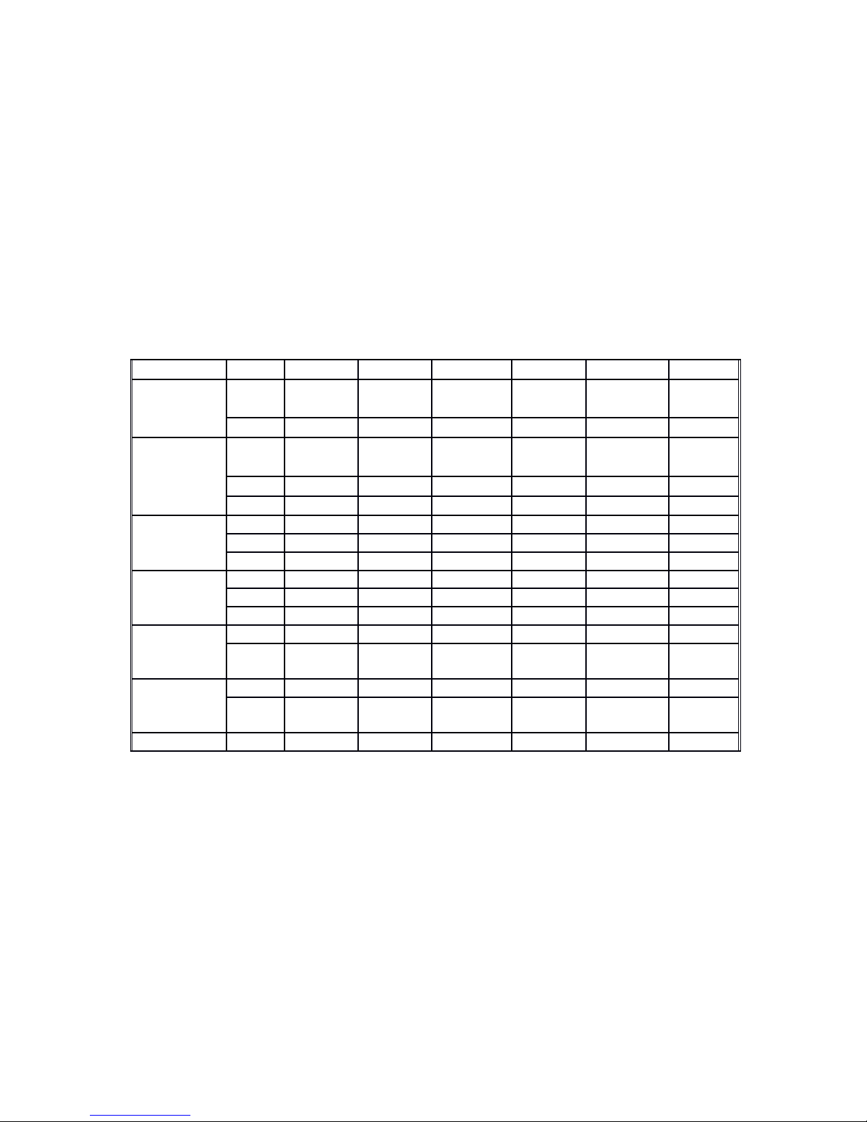
2.4 Testing and measurement range
Table 2 Measurement range
Material Method Impact device
D/DC D+15 C G E D
Steel and
cast steel
HRC 17.9~
68.5
19.3~
67.9 20.0~69.5 22.4~70.7 20.6~
68.2
HRB 59.6~
99.6
47.7~
99.9
37.0~
99.9
HRA 59.1~
85.8 61.7~88.0
HB 127~651 80~638 80~683 90~646 83~663 81~646
HV 83~976 80~937 80~996 84~1042 80~950
HS 32.2~
99.5
33.3~
99.3
31.8~
102.1
35.8~
102.6
30.6~
96.8
Steel HB 143~650
CWT、ST HRC 20.4~
67.1
19.8~
68.2 20.7~68.2 22.6~70.2
HV 80~898 80~935 100~941 82~1009
Stainless
steel
HRB 46.5~
101.7
HB 85~655
HV 85~802
GC. IRON
HRC
HB 93~334 92~326
HV
NC、IRON
HRC
HB 131~387 127~364
HV
C.A UM
HB 19~164 23~210 32~168
HRB 23.8~
84.6 22.7~85.0 23.8~
85.5
BRASS
HB 40~173
HRB 13.5~
95.3
BRONZE HB 60~290
COPPER HB 45~315
2.5 Leeb Hardness Testing Princip e
The basic principle is: use an impact body of certain eight impacts against the testing
surface under certain test force, then measure the impacting velocity and the rebounding
velocity of the impact body respectively hen the spherically test tip is located 1mm
above the testing surface.
The calculation formula is as follo s:
HL=1000×VB/ VA
Where, HL—— Leeb hardness value
VB—— Rebounding velocity of the impact body
VA—— Impacting velocity of the impact body
3 Preparation & Testing
3.1 Preparation & Inspection before Testing
3.1.1Preparation of Samp e Surface
Preparation for sample surface should conform to the relative requirement in the Table 3.
(1) In the preparation processing for sample surface, the hardness effect of being heated
or cold processing on the surface of sample should be avoided.

(2)Too big roughness of the being measured surface could cause measure error. So the
surface of the sample to be measured must appear metallic luster, smoothing and polish,
ithout oil stain.
(3)Support of test sample. Support is no necessary for heavy sample. Medium eight
parts must be set on the smoothing and stable plane. The sample must set absolutely
equability and ithout any obble.
(4)The sample should have enough thickness, and minimum thickness of sample should
conform to Table 3.
(5)For the sample ith hardened layer on surface, the depth of hardened layer should
conform to Table 3.
(6)Curved surface: The best testing surface of sample is flat. When the curvature
radius R of the surface to be tested is smaller than 30mm (D, DC, D+15,C, E and DL type
of impact device) and smaller than 50mm (G type of impact device), the small support
ring or the shaped support rings should be chosen.
(7) Coupling. Light- eight sample must be firmly coupled ith a heavy base plate. Both
coupled surface must be flat and smooth, and there is no redundant coupling agent
existing. The impact direction must be vertical to the coupled surface. When the sample
is a big plate, long rod or bending piece, it can be deformed and become unstable, even

though its eight and thickness is big enough, and accordingly, the test value may not
be accurate. So the sample should be reinforced or supported at its back.
(8)Magnetism of the sample itself should be avoided.
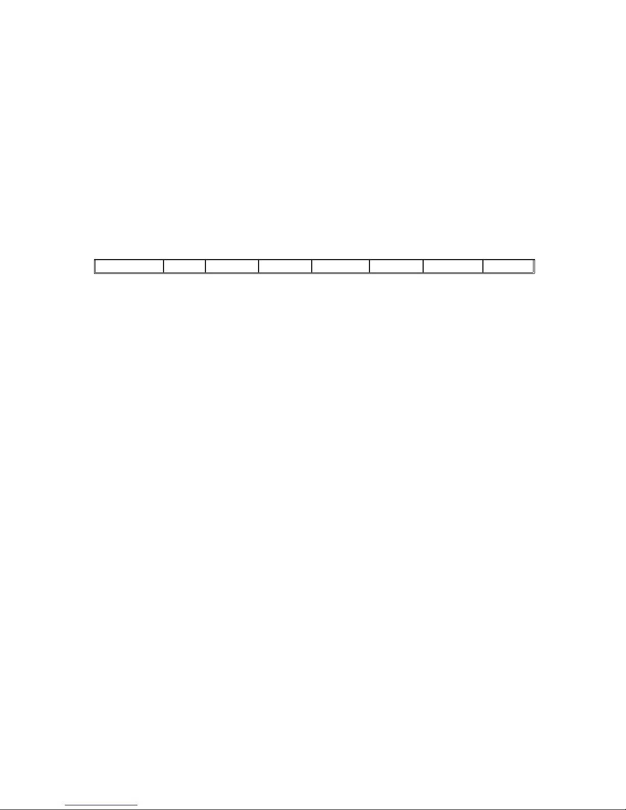
Table 3
3.1.2 System Setting
See 4.5 for details.
3.1.3 Presetting Testing condition
See 4.2 for details.
3.2 Testing Program
Verification of the tester is by using standard test block. The error and repeatability
of displayed value should be ithin the regulation of table 4.
Note:Use a calibrated hardness tester, test the standard test block
downward vertically for 5 times, the arithmetical average value compare with
the value of standard test block. If this value exceeds the standard value,
could use the function of software calibration to adjusting.

3.2.1 Start-Up
(1)Insert the plug of the impact device into the socket of impact device on the tester.
(2)Press key,no po er is connected. The instrument is in testing condition.
Table 4:
3.2.2 Loading
Pushing the loading-tube do n ards until contact is felt. Then allo it to slo ly
return to the starting position or using other method locking the impact body.
Chart 1 Chart 2 Chart 3
3.2.3 Loca ization
Press the impact device supporting ring on the surface of the sample firmly, and the
impact direction should be vertical to the testing surface.
3.2.4 Testing
(1)Press the release button on the upside of the impact device to test. The sample and
the impact device as ell as the operator are all required to be stable no .

The action direction should pass the axis of the impact device.
(2)Each measure area of the sample usually need 5 times of testing operation. The result
data dispersion should not more than mean value±15HL.
(3)The distance bet een any t o impact points or from the center of any impact point to
the edge of testing sample should conform to the regulation of Table 5.
Table 5
(4)If you ant accurate conversion from the Leeb hardness value to other hardness
value, contrastive test is needed to get conversion relations for the special material. Use
inspection qualified Leeb hardness tester and corresponding hardness tester to test at
the same sample respectively. For each hardness value, each measure homogeneously 5
points of Leeb hardness value in the surrounding of more than three indentations hich
need conversion hardness, using Leeb hardness arithmetic average value and
corresponding hardness average value as correlative value respectively, make individual
hardness contrastive curve. Contrastive curve at least should include three group of
correlative data.

4 Operation in Detai s
1.LCD Backlight 2. Standby time 3.Silent mode 4.Time display 5. Sign of HL
6. Measure value by HL 7. Battery status 8. Hardness Scale 9.Times 10.Material
11. Measure value 12. Impact direction
Diagrams of the keyboard
Function of the keys:
●Po er on/off and LCD brightness on/off.
●Menu/Enter
●Cancel or Escape.
●Direction.

●Material.
●Scale.
●Upward/Sa e
●Downward/Delete
●Left/Right.
4.1 Power on
Plug in the impact device, and press to po er on the system. The screen sho s as
belo :
The system ould automatically detect the type of the impact device during po er
up and ould display this information on the screen as belo .
Follo ing is the main display interface as belo .
4.2 Test Set
Pressat the main interface to enter the main menu—Leeb H Tester, as belo . Press

keyorcould continuously glance do n ard or up ard.
Press to enter menu “Set parameter”. Press key or to move the cursor to the line
you ant to set, and press keyto enter submenu.
4.2.1 Hard/σ setting
Press keyor to move the cursor to the line of “Measure H”,and then press key to
s itch H/TS continuously.
Note:
1. H is short for Hardness and TS is short for strength.
2. When H/TS is switched to TS, the hardness scale could not be selected.
3. Only D type of impact device has the function of TS measure. So the impact device could
not be selected.
4.2.2 Impact Direction Setting
Press keyor to move the cursor to the line of “Set DIR” ,and press key to enter

submenu ”Set DIR ” , and then press keyor to choose one of the five kinds of impact
direction such as do n ard, up ard, do n ard 45°, up ard 45° and level180° as
belo . After setting up correctly, press keyto to confirm it and return submenu “Set
parameter”.
Set impact direction using shortcut key:
Press key in main interface to change times quickly.
4.2.3 Materia Setting
When H/TS is preset to hardness, it ill display the follo ing material: Steel and
Cast Steel、Cold Work Tool Steel、Stainless Steel、Gray Cast Iron、Nodular Cast
Iron、Cast Aluminum Alloys、Copper-Zinc Alloys、Copper-Aluminum Alloys、Wrought
Copper and Wrought Steel. And hen H/TS is preset to бb, it ill display the follo ing
material: Mild Steel、High-Carbon Steel、Cr Steel、Cr-V Steel、Cr-Ni Steel、Cr-Mo
Steel、Cr-Ni-Mo Steel、Cr-Mn-Si Steel、Super Strength Steel and Stainless Steel.
Enter submenu”Set Material”, and then press key or to move the cursor to the
Table of contents
Popular Test Equipment manuals by other brands

B+K precision
B+K precision 5105A instruction manual

IKALOGIC
IKALOGIC IkaScope WS200 Datasheet and User Manual

phase II+
phase II+ PHT-3300 manual

Kyoritsu Electrical Instruments Works, Ltd.
Kyoritsu Electrical Instruments Works, Ltd. KEW 4105A instruction manual

AutoMeter
AutoMeter BVA-200s Operator's manual

Ublox
Ublox EVK-F9P-01 user guide


