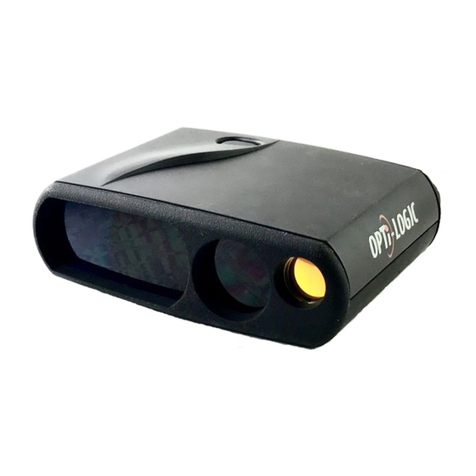
Opti-Logic XT Series User manual

OPTI-Logic XT-Series Tilt-Compensated Laser Rangefinder Manual
Operating Instructions for Models 120XT, 400XT, 600XT, and 800XT and all XP Series
The Opti-Logic XT-Series Tilt-Compensated Laser Rangefinder system combines a pulsed laser rangefinder and a
vertical angle sensor in a lightweight, easy-to-use package that is ideal for shooting applications that require
precision distance measurements uphill or downhill. These hand-held rangefinders are capable of measuring line-of-
sight distances to non-cooperative targets up to 800 yards away (Model 800XT), depending on target size and
reflectivity. Incorporating an internal electronic tilt sensor, the XT-Series Tilt-Compensated Laser Rangefinder is
also capable of automatically correcting for vertical angle with 0.1 degree of resolution to provide the true horizontal
distance to an uphill or downhill target. True horizontal distance is especially important for any applications that
require a projectile to be launched at an angle; for example bow hunting and 3-D Archery, rifle hunting and SWAT
team applications, golfing and much more. This product is designed for years of trouble-free operation and is
proudly made in the USA.
1.0 Product Description and Features
Viewfinder: Look through the viewfinder window and aim the Red Dot at an object.
Range Button: Push the “Range” button to select modes or to activate the Red Dot; Release to
take line-of-sight distance or horizontal distance measurements.
Display: The XT-Series Tilt-Compensated Laser Rangefindersare User Programmable to
read in either Ft, M, or Yd.
Low Battery: Replace the battery when the Low Battery symbol is displayed constantly.
Automatic Timeout: To save batteries, the instrument will automatically power down after about 7
seconds.
2.0 Basic Operation
A. Hold the instrument an inch or two from your eye and aim at the object through the viewfinder.
B. Press and hold the “Range” button. A “Red Dot” will appear in the viewfinder. Place the “Red Dot” on
the target.
C. Release the button and maintain aim on the target momentarily. The laser does not fire until the button
is RELEASED.
D. Read the distance after the Red Dot disappears.
2.1 Distance Measuring with Time-of-Flight Rangefinders
The XT-Series Tilt-Compensated Laser Rangefinder emits invisible, eye safe, pulses of infrared light. Distances are
determined by reflecting the laser beam off an object and measuring the round-trip time-of-flight of the laser beam
to and from the object. The laser beam emitted by the Rangefinder is in the form of a vertical stripe of invisible
light, which enhances the Rangefinder’s ability to hit thin vertical targets. The XT-Series Tilt-Compensated Laser
Rangefinder incorporates a unique “Lock and Load” feature that simplifies the task of hitting targetsin the presence
of background objects. Simply depress the “Range” button and aim the Rangefinder using the “Red Dot” aiming aid
in the viewfinder. The laser is fired AFTER the button is released, which provides time to properly aim the
Rangefinder and minimizes the chance of hitting unintended objects. To improve the accuracy of the instrument, an
onboard computer averages several readings from the object. After the Rangefinder has received enough
information, the Red Dot turnsoff and the distance is shown in the display on the rear panel of the instrument.
The maximum distance measurable by any laser rangefinder is determined by several factors including the size,
shape, reflectivity, and orientation of the object as well as atmospheric conditions. Color and surface finish of the
target also affect the reflectivity and therefore can influence the range as well. A good quality target is a non-gloss

object that is light in color and has enough surface area for the laser beam to efficiently reflect back to the
Rangefinder. Vertical objects tend to make better targets than horizontal ones. White objects tend to range farther
than black objects. Target surfaces that are perpendicular to the laser beam are better than surfaces tilted away from
the Rangefinder. Targets made of “retro-reflectors” provide the greatest range capability. Retro-reflectors are made
of special materials designed to reflect light back toward the light source, for example, stop signs, street signs,
license plates, and specially made Opti-Logic reflectors. Contrary to expectation, extremely glossy surfaces like
windows and mirrors do not make good targets, because they tend to reflect light away from the instrument.
2.2 Changing the 9-Volt Battery
A. Slide the locking tab on the side of the instrument forward (toward the lenses).
B. Using your thumbnail, gently pry out the battery door using the locking tab.
C. Pull on the cloth ribbon and the battery will pop out.
D. Replace battery. The battery direction is shown in the battery compartment. Replace and lock battery door
using slide lock.
2.3 Mode Selection
The Opti-Logic XT-Series Tilt-Compensated Laser Rangefinders provide user-selectable display units and two
operational modes allowing the user to (1) determine line-of-sight distance to an object, and (2) determine true
horizontal range to an object even when the aim point is at a vertical angle. The Opti-Logic XP-Series rangefinder
also includes a third mode enabling the user to read temperature. In Modes 1 and 2, the user may select units of feet,
yards, or meters in either Passive or Reflective settings. To enable the mode selection process, hold the firing button
down for approximately 10-12 seconds until the display is seen to change. Immediately release the button, then
repeatedly press and release the button to scroll through menu options:
Mode 1 Meters (Reflective)
Mode 1 Meters (Non-reflective)
Mode 1 Feet (Reflective)
Mode 1 Feet (Non-reflective)
Mode 1 Yards (Reflective)
Mode 1 Yards (Non-reflective)
Mode 2 Meters
Mode 2 Feet
Mode 2 Yards
Mode 3 Temperature in Degrees Fahrenheit (XP Model only)
Stop tapping the button when the instrument is set to the desired user mode. About 5 seconds after the desired menu
option is selected, the instrument will return to operational mode, AND IMMEDIATELY TAKE A READING.
Mode 1 - Line-of-Sight Distance.Press the range button to activate the Red Dot aiming device and place the Red
Dot on your target. Release the button to fire the laser. HOLD RANGEFINDER ON TARGET UNTIL THE RED
DOT GOES OUT. Read the distance on the external LCD.
Mode 2 -Horizontal Distance (Tilt-Compensated Mode).Press the range button to activate the Red Dot aiming
device. Put the Red Dot on your target. Release the button and wait for the Red Dot to go out. Read the distance in
the LCD. DO NOT MOVE THE UNIT UNTIL THE RED DOT GOES OUT.
Mode 3 – Temperature (XP-Model only).Press and release the range button. The temperature in Fahrenheit
degrees will appear on the LCD display.

3.0 General Care
The Opti-Logic Laser Rangefinder is a sophisticated electronic and optical instrument, built to withstand a
reasonable amount of handling with the same amount of care as any other optical or electronic device, such as a
camera, binoculars, riflescope, telescope, etc. Keeping the lens clean will insure optimum operation and
performance. Use a soft, clean non-abrasive cloth to clean the lenses. Cotton swabs work well. Never use paper or
other abrasive materials. Dampen a cloth with either a very mild soap solution or clean water. Gently rub the lenses
with a dampened cloth. DO NOT SCRUB THE LENSES. After cleaning the lenses, gently wipe the lenses off
with a soft dry cloth. NEVER usepetroleum products or chemicals to clean the lenses or any parts. Use the same
procedure to clean the exterior. Although the Opti-Logic XT-Series Tilt-Compensated Laser Rangefinder has been
designed to withstand normal outdoor use, some common sense precautions should be observed. NEVER subject
your laser rangefinder to shock, high temperature, or harmful chemicals or gases. If the Rangefinder is not going to
be used for long periods of time, remove the battery and store in a cool, dry place. DO NOT use chemicals or
solvents to clean the Rangefinder. Chemicals, insect repellents and solvents can damage the plastic housing and
lenses of the Rangefinder.
4.0 Low Battery Indicator
When the battery voltage becomes too low, the instrument may act erratically or cease to function. The low battery
indicator will appear in the display before this occurs. The battery should be replaced as soon as possible after the
indicator is displayed.
5.0 Error Messages
When a new battery is installed in the XT-Series Tilt-Compensated Laser Rangefinder, diagnostic checks are
performed by the onboard computer. These tests check the basic operation of the Rangefinder after a new battery is
installed. During the normal diagnostic test the display cycles from “000” -“999” and shows all of the LCD display
elements. If the unit is unable to obtain a range or angle measurement, the letters “ERR” will appear on the display.
If the error message persists,
A. Remove the battery for several minutes and then reinstall (it may be necessary to quickly short the
internal battery terminals for 1 second).
B. Make sure the battery terminals are in contact with the internal metal battery clips.
C. Check battery voltage or try a new battery.
Note 1: If the Rangefinder displays an incorrect distance, make sure that the “Red Dot” in the viewfinder is
hitting the object. Try aiming the Rangefinder at a nearby reflective target such as a street sign or
automobile license plate to verify alignment.
Note 2: If the Rangefinder shows a distance of “0”, the Rangefinder is hitting an object at a distance that is
less than the minimum distance. Try aiming the Rangefinder at a more distant object to verify operation.

6.0 Technical Support and Maintenance
For questions regarding the Opti-Logic Laser Rangefinder or if problems persist, make a note of the instrument
serial number and date of manufacture and call Opti-Logic Customer Service at 888-678-4564, 8am to 5pm
Monday thru Friday Central Time. If your rangefinder requires maintenance, your Customer Service
Representative will assign you a Return Merchandise Authorization Number (RMA) and provide instructions for
returning the instrument for repair. When returning merchandise for maintenance or repair, please be sure to include
a brief written description of the problem to:
US Mail: Opti-Logic Corporation Commercial Carrier: Opti-Logic Corporation
P.O. Box 2002 201 Montclair Street
Tullahoma, TN 37388 Tullahoma, TN 37388
6.1 Warranty
Your Opti-Logic Laser Rangefinder is warranted to be free of defects for a period of one year after the date of
purchase. This warranty does not cover defects caused by misuse or improper handling, installation or maintenance
of the product. In the event of a defect under this warranty we will, at our option, repair or replace the product,
provided that you return the product postage prepaid to your authorized Opti-Logic Technical Service Center
including a check in the amount of $15.00 to help cover the cost of handling. (This fee is waived if you discover a
defect within the first 30 days after purchase.) Non-warranty repairs will be made at a cost of $25.00 plus the cost
of any plastic replacement parts.
7.0 Specifications
Model Number: 120XT, 400XT, 600XT, 800XT and XP-series
Approx. Size: 1.7” x 4” x 5.1”
Weight: 11 oz
Operational Range: 120XT 5-150 yards passive, up to 500 yards reflective
400XT 5-400 yards passive, up to 999 yards reflective
600XT 5-600 yards passive, up to 999 yards reflective
800XT 5-800 yards passive, up to 999 yards reflective
Range Accuracy: +/-1 yard (+/-2 yards for very dark or very bright targets).
Readout: Easy to read external LCD display.
Units of Measure: User Programmable in either FEET, METERS, or YARDS.
Viewfinder: Monocular viewing port. Red LED aiming sight, +/-0.1 degrees
Battery: Single 9 volt battery. Operates for approximately 1000 shots.
Operational Temperature: 0°- 40°C, 32°-104°F. Relative Humidity 5-95% non-condensing.
Laser Type: Infrared Class 1, eye safe 905nm Laser.
This manual suits for next models
5
Table of contents
Other Opti-Logic Measuring Instrument manuals
Popular Measuring Instrument manuals by other brands

Unico
Unico S-1100 Operation manual

socomec
socomec DIRIS A40 Operating instruction

ICS Schneider Messtechnik
ICS Schneider Messtechnik Anton Paar DMA 501 Instruction Manual and Safety Information

Omron
Omron K3MA-J Series manual

NEC
NEC Express5800/A1040b user guide

Thermo Electron
Thermo Electron Nicolet 380 user guide