manuals.online logo
Brands
  1. Home
  2. •
  3. Brands
  4. •
  5. Optical Structures
  6. •
  7. Accessories
  8. •
  9. Optical Structures Astrodon MonsterMOAG MMOAG-1 User manual

Optical Structures Astrodon MonsterMOAG MMOAG-1 User manual

This manual suits for next models

3

Popular Accessories manuals by other brands

Quincy lab 140AE-1 operating manual

Quincy lab

Quincy lab 140AE-1 operating manual

HomePro ZIR000 user manual

HomePro

HomePro ZIR000 user manual

DOL 20SCR Technical user guide

DOL

DOL 20SCR Technical user guide

RAB Smart Task installation manual

RAB

RAB Smart Task installation manual

Kemppi KMS 300 quick guide

Kemppi

Kemppi KMS 300 quick guide

Stearns 57,500 Series Installation and service instructions

Stearns

Stearns 57,500 Series Installation and service instructions

iGuzzini TWILIGHT COPENAGHEN manual

iGuzzini

iGuzzini TWILIGHT COPENAGHEN manual

Adelaide Annexe & Canvas Avan Deluxe installation guide

Adelaide Annexe & Canvas

Adelaide Annexe & Canvas Avan Deluxe installation guide

OHAUS 5000 instruction manual

OHAUS

OHAUS 5000 instruction manual

HOME8 WLS1300 quick start guide

HOME8

HOME8 WLS1300 quick start guide

MAXBOTIX MaxSonar quick start guide

MAXBOTIX

MAXBOTIX MaxSonar quick start guide

ioSmart iSmart56 Installation and user guide

ioSmart

ioSmart iSmart56 Installation and user guide

Focusrite Scarlett 18i8 user guide

Focusrite

Focusrite Scarlett 18i8 user guide

Velleman ED38105 user manual

Velleman

Velleman ED38105 user manual

JumpSport SkyBounce user manual

JumpSport

JumpSport SkyBounce user manual

Prima-Temp PRIYA Instructions for use

Prima-Temp

Prima-Temp PRIYA Instructions for use

Tefcold BC85I-BC85I W user manual

Tefcold

Tefcold BC85I-BC85I W user manual

Vaisala WMS302 user guide

Vaisala

Vaisala WMS302 user guide

manuals.online logo
manuals.online logoBrands
  • About & Mission
  • Contact us
  • Privacy Policy
  • Terms and Conditions

Copyright 2025 Manuals.Online. All Rights Reserved.

MonsterMOAG™Off-Axis Guider
for 2 inch focuers
Part #: MMOAG-1, MMOAG-2, MMOAG-3 & MMOAG-4
2
Introduction
The MonsterMOAG™ (MMOAG) is the our most
popular off-axis guider (OAG) from Astrodon©
designed for CCD imaging.
It is designed to have a large (2.55”; 65 mm)
opening with its 2.7” threaded fittings. It is suitable for the
largest imaging detectors (KAF16803, KAF09000) with
dimensions of 36x36mm and a 52 mm diagonal.
To the best of our knowledge, the MMOAG is
one of the thinnest OAG available, taking up only
1.25” of backfocus (1.45” with connectors). It is
thin enough to be used on the Takahashi
FSQ106N refractor, with its very short 4.75”
(120mm) backfocus.
The MMOAG was modified in June, 2015. The rectangular body
was made square and the through hole for the prism/focuser
assembly was replicated on all sides. This enables up to four
guiding ports to be used. We refer to these as MMOAG-1, -2, -3
and -4 where the number represents the number of guide ports
occupied. You can add additional ports later. Any unused port
comes covered with a black plate with an indent that protrudes
into the hole to block any light from entering the MMOAG.
3
Features
Solid aluminum body for no flexure, 3.1 x 3.1 x 1.23”
Supplied with male and female adaptors (1 each)
o2.7”-24TPI threads
(TPI, threads per inch)
oDovetail connection to
MMOAG
Allows for
rotation and
lock down on both sides
Dovetail pulls 3.2”dia. knurled flange
against MMOAG body for no camera tilt
Male adaptor has low reflectivity I.D.
Female adaptor has 2.7”-24 threads on
the I.D. and 3.00-24” male threads on
the O.D. compatible with the new, large
filter wheels
Optional adaptors for the camera side of varying
thicknesses (backfocus) –see web site.
oProvides additional
space to bring the focus
above the helical
focuser for some
camera/CFW
combinations
oMakes a direct
connection between
MMOAG and large CFW
from Apogee/Andor 7S), SBIG and Finger Lake
Instruments, also with rotation and lock down
Helical focuser for 1.25” nose piece of guiding camera
for fine focus adjustment
½ ” AR-coated right-angle prism
Additional 0.125” spacer provided to extend prism
further into the optical path
1.1 lbs (0.49 kg) with body, connectors and helical
focuser
4
Slots for rotation on the focuser holder for fine
alignment of the prism parallel to the optical axis
Dimensions
5
Installation Issues
The flat side of the prism and the male 2.7” AP adaptor face the
telescope.
We suggest that you remove the male fitting by loosening the 8-
32 set screws in the MMOAG raised flanges with a 5/64 ball
driver or with the provided hex wrench set. Screw the adaptor
into a female AP 2.7” compatible extension tube or connector
on your telescope. The MMOAG adaptor has a knurled, raised
3.20” diameter flange that can be used to tighten or to remove
it.
Next, place the MMOAG over the dovetail fitting and proceed to
tighten the four 8-32 set screws. As you tighten, the MMOAG
body will be pulled flush against the 3.20” raised flange on the
adaptor to minimize any camera tilt.
Repeat this process on the camera side. There are several
options. Use the supplied adaptor with the female AP 2.7”
threads to accept a connector with male AP 2.7” threads. For
example, there is an STL-to-AP(male) adaptor that screws into
the SBIG STL nose plate. Simply screw the supplied 2.7”
MMOAG female adaptor onto this part, insert into the MMOAG
body and tighten down as before. You can place AP
(www.astro-physics.com) extension tubes between the male
and female 2.7” parts in this way.
6
The MMOAG female adaptor also has 3.000”-24 male threads
on the outside that are 1/8” long. These fit into the new, large
CFWs from Apogee Instruments
(www.ccd.com ), SBIG (www.sbig.com), and Finger Lakes
Instruments (www.fli-camera.com). However, the “overhang”
of the holder for the helical focuser on top of the MMOAG may
interfere with the CFW.
There are two solutions. First, you can purchase our optional
0.75” long adaptor having the dovetail on one side and 3.000”-
24 threads on the other or other adaptors (please see our web
page). Second, you can move the focuser holder up 0.1” with
the additional (3 x 3.4”) spacer provided.
We provide one additional 0.125” thick (1 ¼ x 9/16”) spacer that
fits underneath the prism holder. This permits you to move the
prism further into the optical path and away from the edge of
the field of view. This can be beneficial for better focus if the
flat field does not extend to the periphery of the I.D. Also, you
have more flexibility along these lines with smaller detectors
while still minimizing any vignetting.
Remove the camera from the focuser. Remove the two 4-40
button head screws (BHCS) on the slotted tabs of the focuser
holder with a 1/16 ball driver or with the hex wrench from the
provided set. Pull the assembly out of the MMOAG body.
Remove the two 4-40 socket head cap screws (SHCS) from the
7
prism holder (3/32” ball driver/wrench), being careful not to let
the prism fall and chip and edge. Add the additional spacer and
reconnect the prism holder and prism. Re-insert the assembly
into the top of the MMOAG and secure with the two 4-40 cap
screws.
Please note that the 4-40 button head screws fit into slots in the
focuser holder. This allows you to rotate the prism to ensure
that its face is perpendicular to the optical axis of the scope.
You may make this adjustment on the telescope and then
tighten it securely. I use a Farpoint Laser Collimator placed on
top of the helical focuser on a table. I then align the edge of the
MMOAG body against a rail. I then move a target along that rail
closer and further away from the MMOAG. If the prism is
aligned, the laser spot will not move side to side. If it does
move, I make fine rotation adjustments to the focuser holder
and repeat the process until no movement is observed. I then
tighten down the BHCS and lock the prism holder in place.
MonsterMOAG with Farpoint
laser collimator pointing
down into prism.
8
Laser spot is seen on a target
about 6” away. Note the
target is held fixed along the
side of the table with the
same plate.
Laser spot is seen on target
about 2’ away, again aligned
with the table using the
metal plate. Note that the
spot has not moved left or
right.
Coming to Focus
It is important to realize that any
OAG must be placed within a narrow
range of distances from the imaging
camera for the guiding camera to
come to focus. The distance
between the prism and guide
camera focal plane (A) must equal
the analogous distance between the
9
prism and the focal plane of the imaging camera (B). If too
close, the focal point will be inside the helical focuser on the
MMOAG. If too far, the focal point may be too far above the
focuser, and require an eyepiece extender or just be too far
away to be stable. Please see our web page for a more current
set of distances and help
The backfocus distances for some popular large format cameras
at the time of this writing are:
Finger Lakes Proline + CFW-4-7s - 1.8”
Apogee U16M + AI-FW50-7s - 2.0”
SBIG STL/FW8 + STL-to-AP(male) adaptor - 2.2” (1.9”
with internal CFW)
Add the midpoint of the MMOAG where the prism is located to
these numbers, plus the 0.1” raised flange of the fitting (0.625 +
0.1 = 0. 725”), and the values for Bbecome:
FLI Proline + CFW-4-7s + MMOAG - 1.8+ 0.7” = 2.5”
Apogee U16M + AI-FW50-7s + MMOAG - 2.0” +
0.7” = 2.70”
SBIG STL/FW8 + STL-to-APmale adaptor + MMOAG -
2.2” (1.9” with internal CFW) + 0.7” = 2.9”
The minimum distance Awith the helical focuser screwed all the
way in is 2.8”. Add 0.6” for the backfocus of guider cameras,
such as the SBIG ST-402 and the minimum distance Abecomes
3.4”. The helical focuser has approximately ½” of travel. So, it
10
would be useful to plan for the mid-range of travel, or 3.4” +
½(1/2) = 3.6” as the target for A.
There are several ways to increase Band/or decrease Ato
arrive at focus.
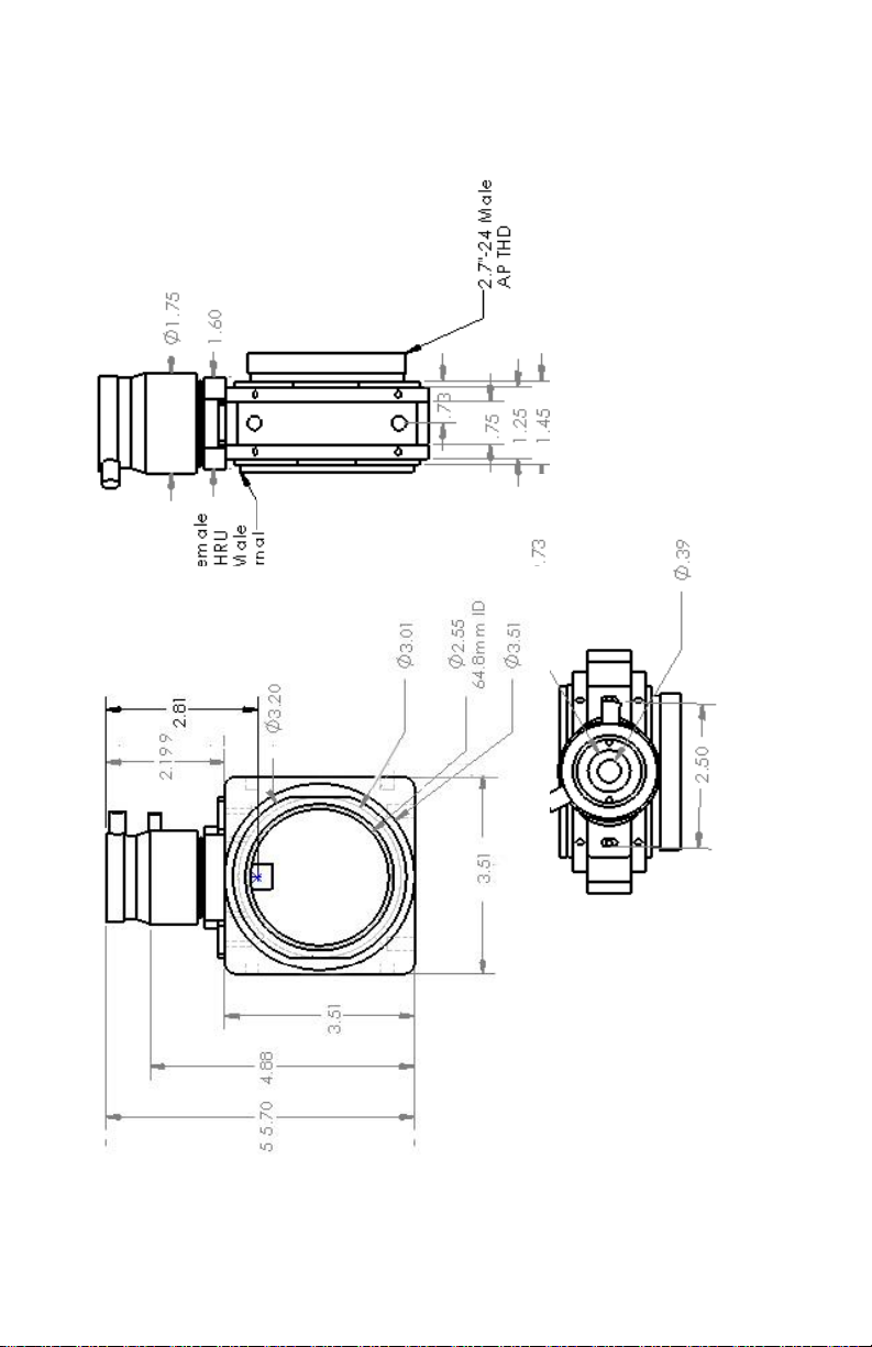
1. Use a 2.7” male fitting on your CFW. Add the
appropriate AP extension tube to achieve >3.65” for B.
Connect directly into the AP Female 2.7” adaptor
provided with the MMOAG. The guider nose piece does
not have to be placed flush into the focuser. It can be
retracted perhaps ¾”. Disadvantage –purchasing of a
2.7” male fitting for your CFW and AP extension tubes.
2. Replace the helical focuser with the provided 1.25”
nose-piece holder decreasing Afrom 3.6” to 2.7” AND
purchase the additional dovetail-to-3”male 0.75” long
adaptor. This makes Bfor YR, Apogee and FLI 3.08”,
3.24” and 3.51”, respectively. In this way, the guide
camera can be partially retracted from the nose piece
and then locked in place to achieve focus.
Disadvantage –losing the fine focus capability of the
helical focuser.
Another Way to Attach the Guide Camera
We have learned that the outside threads on the helical focuser
match the internal threads in SBIG remote guide head (RGH)
and ST-402 guide cameras. This allows the guider to be moved
closer to the prism by eliminating the 1.25” nose piece, if focus
cannot be achieved otherwise.