This symbol is intended to alert the user to
the presence of important operating and
maintenance (servicing) instructions in the
literature accompanying the appliance.
WARNING!
DO NOT EXPOSE THIS EQUIPMENT
TO RAIN OR MOISTURE
This symbol is intended to alert the user to the
presence of uninsulated “dangerous voltage”
within the product’s enclosure that may be of
sufcient magnitude to constitute a risk of
electric shock to persons.
CAUTION
RISK OF ELECTRIC SHOCK
DO NOT OPEN
THIS EQUIPMENT MUST BE EARTHED
1. Read these instructions.
2. Keep these instructions.
3. Heed all warnings.
4. Follow all instructions.
5. Do not use this apparatus near water.
6. Clean only with a dry cloth.
7. Do not block any ventilation opening. Install in accordance with the
manufacturer’s instructions.
8. Do not install near any heat sources such as radiators, heat registers,
stoves, or other apparatus (including ampliers) that produce heat.
9. To reduce the risk of electrical shock, the power cord shall be
connected to a mains socket outlet with a protective earthing
connection.
10. Do not defeat the safety purpose of the polarized or grounding type
plug. A polarized plug has two blades with one wider than the other.
A grounding type plug has two blades and a third grounding prong.
The wide blade or the third prong are provided for your safety. If the
provided plug does not t into your outlet, consult an electrician for
replacement of the obsolete outlet.
11. Protect the power cord from being walked on or pinched particularly
at plugs, convenience receptacles, and the point where they exit from
the apparatus.
12. Do not unplug the unit by pulling on the cord, use the plug.
13. Unplug this apparatus during lightning storms or when unused for
long periods of time.
14. Refer all servicing to qualied service personnel. Servicing is required
when the apparatus has been damaged in any way, such as power
supply cord or plug is damaged, liquid has been spilled or objects have
fallen into the apparatus, the apparatus has been exposed to rain or
moisture, does not operate normally, or has been dropped.
15. The appliance coupler, or the AC Mains plug, is the AC mains
disconnect device and shall remain readily accessible after installation.
16. The apparatus shall not be exposed to dripping or splashing and
no objects lled with liquids, such as vases, shall be placed on the
apparatus.
17. Do not remove any covers, loosen any xings or allow items to enter
any aperture.
Important Safety Instructions FCC Compliance
This device complies with part 15 of the FCC Rules. Operation is subject to
the following two conditions:
1. This device may not cause harmful interference.
2. This device must accept any interference received, including
interference that may cause undesired operation.
Note: This equipment has been tested and found to comply with the limits
for a Class B digital device, pursuant to part 15 of the FCC Rules. These
limits are designed to provide reasonable protection against harmful
interference in a residential installation. This equipment generates uses
and can radiate radio frequency energy and, if not installed and used in
accordance with the instructions, may cause harmful interference to radio
communications.
9/10
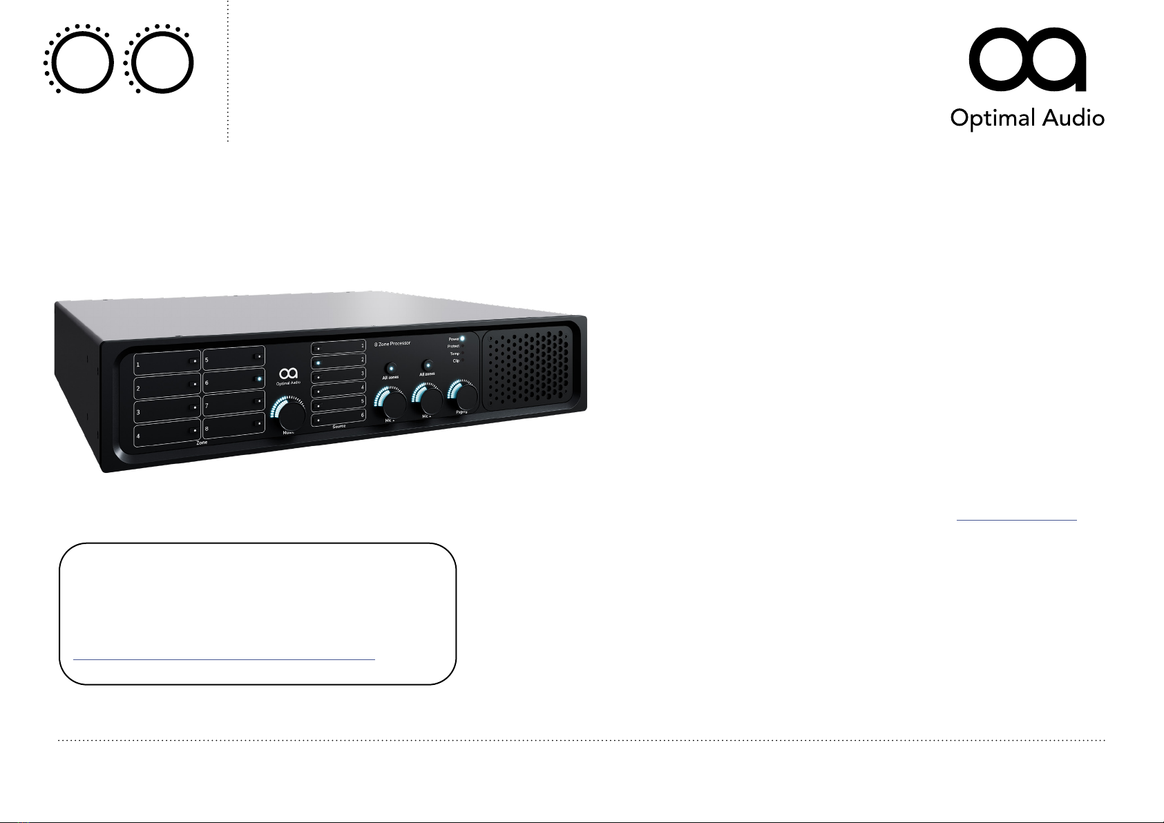
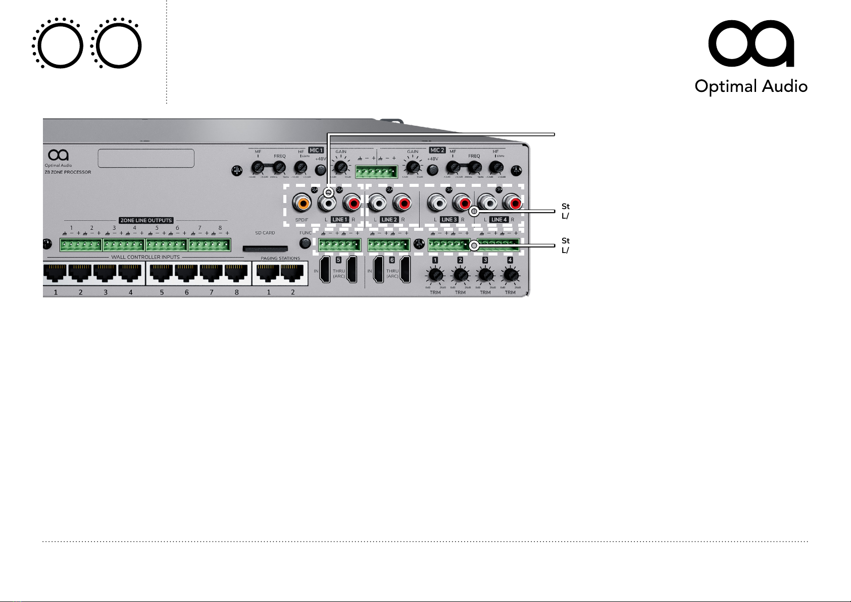
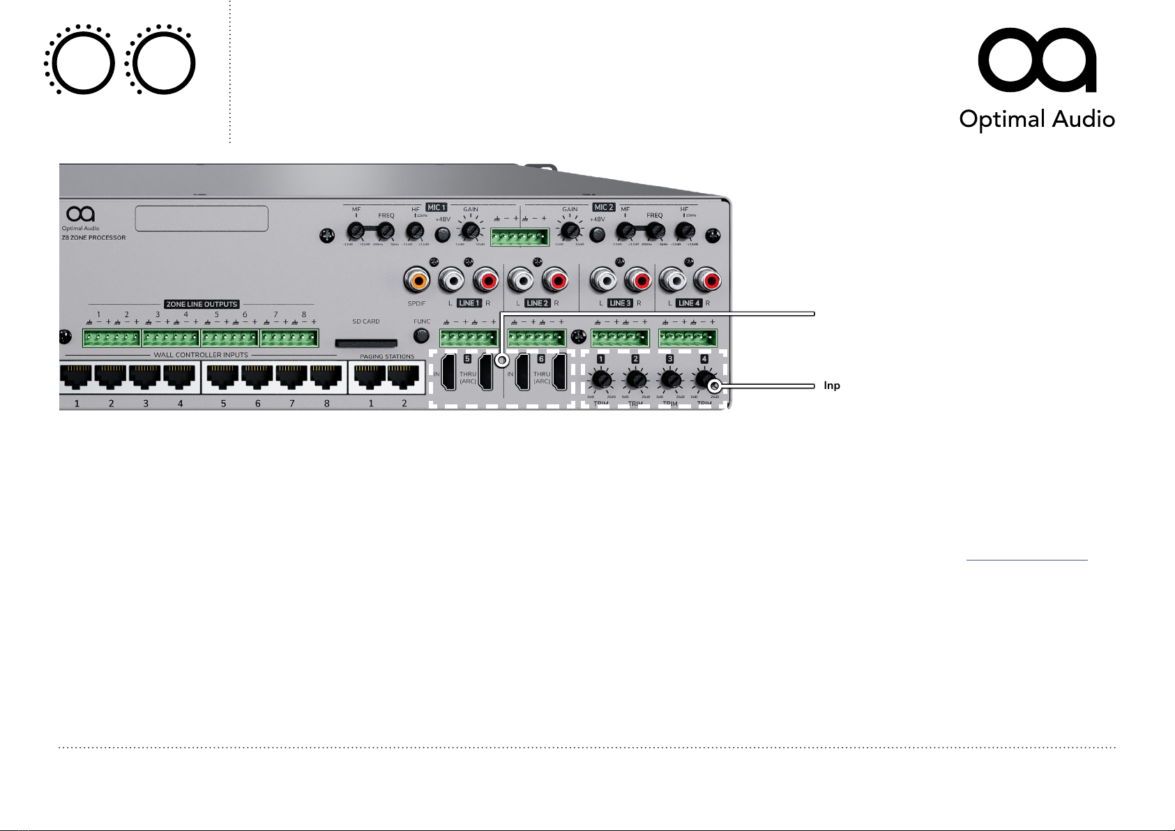
Zone 8
8 zone audio controller with DSP and WebApp
Controllers
USER GUIDE
© 2021. Optimal Audio Group Ltd. (v1.2)