Page 3
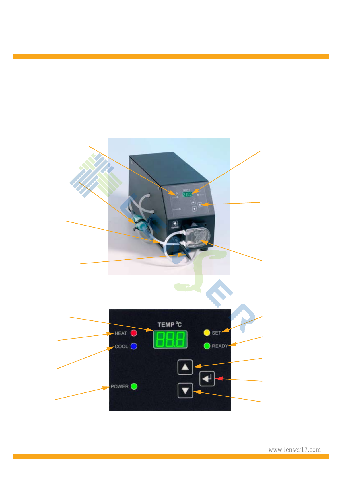
TC20i Temperature Control Instrument
Set-Up Detail
1. Position the TC20i to the right of the Optimec JCF, JCM, SAG, JCFD or is830 instrument.
2. On the left hand side of the TC20i is a cooling fan and it is EXTREMELY IMPORTANT
that it is not obstructed, and that a minimum 10cm space is maintained beteween it and
any other object. Failure to do will restrict the air flow and may result in the failure of the
internal heat exchanger.
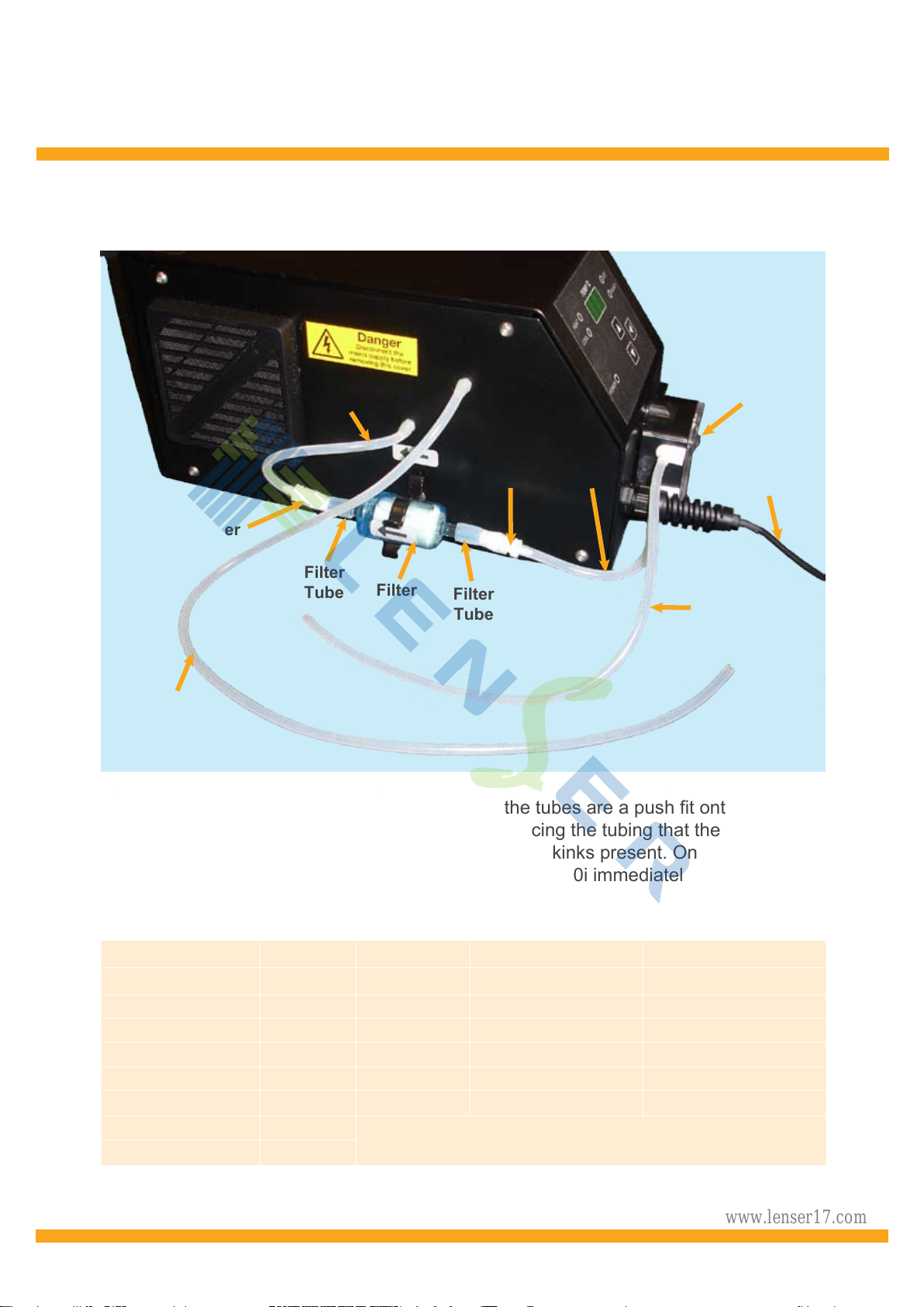
3. Take the clear silicon tube leading from the top of the Peristaltic Pump and connect to the
plastic tube connector on the right hand side of a JCF and JCM analysis cell or to the
upper connector of the manifold block on the right hand side of a SAG instrument.
4. Take the clear silicon tube leading from the side of the TC20i cabinet (longest tube) and
connect to the plastic tube connector on the left hand side of a JCF,JCM, JCFD or is830
analysis cell or to the lower connector of the manifold block on the right hand side of a
SAG instrument.
5. Position the temperature sensor in the analysis cell of the JCF or using the clip bonded
into the analysis cell of a JCM, SAG or is830 instrument.
6. Fill the analysis cell with saline to the correct level (see JCF, JCM, JCFD,SAG or is830
manual).
7. Insert the power lead included with the TC20i into the plug at the rear of the instrument
and switch on the power at the wall. Switch on the TC20i using the switch at the rear
of the instrument.
8. The Green LED (Power) will illuminate to confirm that the instrument is on.
9. When switched on the Peristaltic Pump will rotate and draw saline from the analysis cell
As this happens, the saline level in the cell will fall and bubbles will be seen as the pump
expels air during priming. Top up the saline level in the cell until bubbles no longer appear.
WARNING:
IF SALINE IS SPILT, DISCONNECT THE TC20i FROM THE ELECTRICAL SUPPLY
Avoid spilling saline on the TC20i as it is very corrosive, damaging the paintwork, and should
it come into contact with the electronics, may cause a serious instrument failure and possibly
a risk of electric shock.
WARNING:
DISCONNECT FROM THE POWER SOURCE if the side panels may be removed to check
that no saline is in the cabinet, and left to dry naturally if there is. This is the only circumstance
for the side covers to be removed as there are no user serviceable parts within the cabinet.
总代理:上海朗善光学仪器有限公司 www.lenser17.com