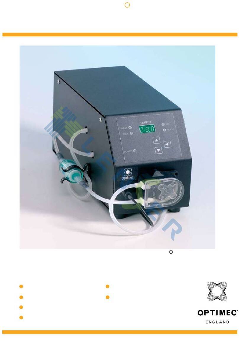
Optimec JCF/F Training manual

User Manual & Operating Instructions
Diameter
BCOR
Centre Thickness
Highly Accurate
Bright, High Contrast Image
Optimec Limited 2016
c
Surface/Edge Inspection
Quick & Easy to Operate
In built Saline Filtration
Optimec JCF/F
R
Optimec Document No D20150-00
Soft contact lens metrology
总代理:上海朗善光学仪器有限公司 www.lenser17.com

Page 1
CONTENTS
Front Cover - Photograph of JCF/F Instrument
Page 1 - Contents
Page 2 - Instrument Set-Up Details: Mirror Plate
Page 3 - Cell Details: Cell Front View
Page 4 - Cell Details: Cell Side View
Page 5 - Cell Details: Cell Top View
Page 6 - Instrument Set-Up Details: Cell and Tube Fitting
Page 7 - Instrument Set-Up Details: Pump and Filter Tubing
Page 8 - Instrument Set-Up Details: Cell Positioning
Page 9 - Instrument Operating Instructions
Page 10 - Instrument Operating Instructions
Page 11 - Users Information
Page 12 - Technical Specifications
Page 13 - Guarantee Conditions
Page 14 - Certificate of Conformity
Back Cover - Contact Details
User Manual & Operating Instructions
Contents
总代理:上海朗善光学仪器有限公司 www.lenser17.com

THE MIRROR IS FRAGILE AND MUST BE TREATED CAREFULLY. CLEAN AS FOR ANY
OPTICAL COMPONENT USING A GOOD QUALITY LENS CLOTH.
THE UPPER MIRROR PLATE HAS BEEN DETACHED FROM ITS CABINET MOUNTS TO
PROTECT IT DURING TRANSIT.
TO FIT THE MIRROR PLATE:
1. Lay the cabinet on its back onto a non-scratch surface.
2. Remove the two thumb nuts and two shake proof washers from the studs on the
under surface of the top panel.
3. Carefully unwrap the mirror plate assembly and place over the two studs.
4. The centre thickness adjusting scew must be placed at the upper left hand corner.
5. Hold the assembly in position whilst fitting the two shake proof washers and the
thumb nuts to the studs.
6. Finger tighten the thumb nuts securing the mirror plate assembly in place.
7. Ensure the mirror is clean, removing any smears or dust using a good quality
glass/lens cloth and glass cleaner.
8. Stand the cabinet assembly on its feet ready for the cell to be fitted.
Page 2
Thumb
Nut to
mount
Mirror
Plate
Adjusting
Screw for
Centre
Thickness
DO NOT
REMOVE
Thumb
Nut to
mount
Mirror
Plate
FACTORY SET DO NOT
ADJUST OR REMOVE
Mirror
DO NOT
SCRATCH
JCF/F Set Up Details
Fitting the Mirror Plate
Mirror Plate Assembly
总代理:上海朗善光学仪器有限公司 www.lenser17.com

Page 3
Radius
Wheel
Cell
Fixing
Screw
Focus and
Centring
Knob
Drainage
Tube
Drainage
Tube
Retaining
Clip
Radius
Wheel
Scale
Radius
Scale
Mark
Radius
Wheel
Clamping
Screw
DO NOT
REMOVE
DO NOT
REMOVE
IT IS IMPORTANT THAT THE TWO SCREW COVERS
AND THE SCREWS UNDERNEATH ARE NOT REMOVED
AS CELL BREAKAGE MAY OCCUR
JCF/F Cell Details
Cell Front View
总代理:上海朗善光学仪器有限公司 www.lenser17.com

Page 4
Radius
Wheel
Focus and
Centring Knob
Radius
Wheel
Clamping
Screw
Cell
Fixing
Screw
Drainage
Tube
Drainage
Tube
Retaining
Clip
Radius
Scale
Mark
Radius
Wheel
Scale
JCF/F Cell Details
Cell Side View
总代理:上海朗善光学仪器有限公司 www.lenser17.com

Page 5
Radius
Wheel
Focus and
Centring Knob
Probe
LEFT: Surface Inspection Cell
Cylinder
Centring
Platform
RIGHT: Radius Cell
‘V’Graticule
‘V’
JCF/F Cell Details
Cell Top View
总代理:上海朗善光学仪器有限公司 www.lenser17.com

Page 6
JCF/F Operating Instructions
Fitting the Cell
THE UPPER SCREWS ON THE SIDE MOUNTING BLOCKS ARE COVERED AND MUST
UNDER NO CIRCUMSTANCES BE REMOVED. TO DO SO WILL RESULT IN BREAKAGE
OF THE CELL. TO FIT THE CELL:
1. Carefully unpack the cell onto a scratch proof surface.
2. The cell mounting blocks are fitted to the cell by two screws protected by covers.
UNDER NO CIRCUMSTANCES REMOVE THESE SCREWS.
3. Below the covered screws are holes which allow access to the cell mounting screws.
4. Offer the JCF cell to the cabinet front panel, so that the cell fixing screws which
protrude through the cell mounting blocks, locate into the cabinet front panel holes.
5. Place the Allen key supplied through the left hand 6mm hole and locate into the
captive nut giving the screw 3 complete turns.
6. Next place the Allen key through the right hand 6mm hole and locate into the captive
nut giving that screw 3 complete turns.
7. Continue to tighten the two screws alternatively until the cell is secure.
8. Do not tighten fully as the cell postion needs to be adjusted.
Fitting the Pump Tubing
1. Check that the Drain Tube on the right hand side of the Cell is retained vertically by
its clip.
2. Fit the tube from the pump outlet to the left hand side of the Cell and the tube from the
filter inlet to the right hand side of the Cell.
3. Fill the Cell with fresh, 0.9% saline to within 5mm of the top. There is a small recess
moulded into the top left rear wall of the Cell. Filling to the lower edge of this recess
will give the correct amount of saline.
4. Insert the power supply lead, plug into the electricity supply and switch on.
5. Switch on the pump using the Blue switch and top up the saline in the Cell as the
saline it fills the tubing and filter.
Cell Adjustment
1. Select the base curve measuring function and adjust the cell position by hand until the
measuring cylinder is equally positioned about the left hand edge of the illuminate
centre thickness scale, and is parallel to the screen fixing strip.
2. Tighten the cell mounting screws. DO NOT OVERTIGHTEN.
总代理:上海朗善光学仪器有限公司 www.lenser17.com

Page 7
JCF/F Set-up Details
Pump and Filter Tubing
Power
Switch
(Green)
Peristaltic
Pump
Pump
Inlet
Pump
Outlet
Filter
Filter
Outlet
Filter
Inlet
Pump
Switch
(Blue)
from
Pump
Outlet
to
Filter
Inlet
总代理:上海朗善光学仪器有限公司 www.lenser17.com

Page 8
1. When the cell is correctly positioned the view above will be seen.
2. The top face of the Cylinder should be parallel to the top of the Screen Fixing Strip.
3. The centre line of the Probe to be equally positioned either side of the left hand edge
of the illuminated Centre Thickness Scale.
JCF/F Set Up Details
Cell Positioning
PARALLEL
= =
EQUAL
Viewing
Mode
Switch
Screen
Fixing
Strip
Cylinder
Centre
Thickness
Scale
Probe
Power
Switch
(Green)
Pump
Switch
(Blue)
总代理:上海朗善光学仪器有限公司 www.lenser17.com

Page 9
1. With the contact lens still in position, rotate the Radius Wheel anti clockwise to raise
the Probe up the centre of the Cylinder until the tip of the Probe just touches the
back (concave) surface of the contact lens. In practice the Probe is raised and
lowered slightly a couple of times until the smallest movement of the contact lens
front surface, relative to the lines on the Centre Thickness Scale, is just visible.
2. Read the BCOR directly (in mm) from where the Radius Scale Mark meets the
Radius Wheel Scale.
1. Do not move the Probe from its position following the BCOR measurement.
2. Using the Centre Thickness Scale Adjusting Knob in the top left hand side of the
cabinet. Adjust the image position so that the Screen Thickness Scale aligns with the
front surface image of the contact lens.
3. Leaving the Probe and Centre Thickness Scale in position, transfer the contact lens
(convex side up) into the LEFT: Surface Inspection Cell.
4. Read the centre thickness directly (in mm) from the Centre Thickness Scale at the
image of the Probe tip.
1. Check that the Viewing Mode Switch is to the right.
2. Rotate the Radius Wheel clockwise to retract the probe in the Radius Cell
until the BCOR reading is 9.5mm on the Radius Wheel Scale.
3. Turn the Focussing and Centring Knob to raise the Centring Platform level with the
top of the Cylinder.
4. Place the contact lens, convex side up on the Centring Platform over the Cylinder.
5. Using the Focussing and Centring Knob, raise and lower the contact lens until it
rests symmetrically on the Cylinder.
6. Lower the Centring Platform clear of the image.
7. Examine the edge profile of the contact lens.
JCF/F Operating Instructions
Right: Radius Cell
Radius Measurement
Centre Thickness
总代理:上海朗善光学仪器有限公司 www.lenser17.com

Page 10
1. The contact lens is placed convex side up on a ‘V’ Graticule which slopes 10 degrees
allowing the contact lens to slide into position against the ‘V’, and a plan view image
of the whole contact lens is projected on to the screen.
2. Switch the Viewing Mode Switch to the left.
3. Ensure the contact lens rests against the ‘V’.
1. With the contact lens in position use the Focus and Centring Knob to bring the outside
edge image of the contact lens, and the two diameter scale images, into focus.
2. Read the two diameter measurements directly (in mm).
3. A comparison of these two measurements will show any eccentricity of the contact
lens.
1. With the outside edge of the contact lens in focus the complete edge can be
inspected.
2. Using the Focus and Centring Knob, focus through the whole depth of the contact
lens for a full surface inspection.
JCF/F Operating Instructions
Left: Surface Inspection Cell
Diameter Measurement
Surface Inspection
总代理:上海朗善光学仪器有限公司 www.lenser17.com

Page 11
SETTING UP
1. Replace contact lenses into original containers.
2. At end of day empty the cells through the drain tubes, rinse thoroughly with DI
(distilled water) before drying the instrument.
3. When the JCF/F is not in use, always turn off the power and fit the dust cover.
4. Use lens cloths only for cleaning JCF/F optics.
5. If saline is spilled, disconnect the power supply and mop up with a clean damp cloth.
IMPORTANT: DO NOT USE ABRASIVE CLEANERS, METAL INSTRUMENTS, SOLVENTS
OR DISINFECTANTS EXCEPT HYDROGEN PEROXIDE 3%
1. To change an OPTIMEC LED light engine, ENSURE THE INSTRUMENT HAS COOLED
DOWN AND IS DISCONNECTED FROM THE POWER SUPPLY.
2. Remove the Rear Cover Plate Screw and then the Rear Cover Plate. Disconnect the
two bullet wiring connectors from the existing LED light engine and, holding the LED
light engine tube, pull it rearwards and away from the instrument light tube.
3. Push the new light engine tube fully over the instrument light tube and refit the bullet
wiring connectors. Replace Rear Cover Plate and reconnect to the power supply.
4. Keep the JCF clean and dry at all times, this will dramatically improve the life of the
instrument. Most repairs required of the JCF are due to saline contamination and
associated corrosion.
1. Set the supplied 8.5mm BCOR Radius Calibration Button into the RIGHT: Radius Cell
centrally on the Cylinder.
2. Turn the Radius Wheel anti clockwise to raise the Probe until it just touches the back
surface of the Radius Test Button.
3. Read the scale on the face of the Radius Wheel. If the reading is the same as the
Radius Calibration Button dimension, the instrument calibration is correct.
4. If the JCF requires adjustment; with the Radius Calibration Button still in position,
slightly loosen the two Wheel Clamping Screws on the underside of the Radius wheel.
5. Turn the Radius Wheel until the Radius Scale is at the correct reading and retighten
the Wheel Clamping Screws.
6. Recheck the calibration.
JCF/F Users Information
Best Practice
Calibration
Maintenance
总代理:上海朗善光学仪器有限公司 www.lenser17.com

Page 12
SETTING UP
IMPORTANT
IMPORTANT ....... FOR SAFETY AND OPTIMUM INSTRUMENT LIFE IT IS
ESSENTIAL TO ALWAYS USE:
12V 6.6W OPTIMEC LED light engine.
Replacements may be obtained from Optimec Limited.
JCF/F Instrument Specification
Technical Specification
Height
(mm)
Width
(mm)
Depth
(mm)
Weight
(kg)
Electrical
Options
Projection
Lamps
Approx Power
Consumption (watts)
589 374 350 16 19
BCOR
Range
(mm)
6.9 - 9.5
0.05mm Divisions
Accuracy
(mm)
(+/-) 0.02
oC
Diameter
Range
(mm)
6 - 16
0.1mm Divisions
Accuracy
(mm)
(+/-) 0.025
Saggital
Height Range
(mm)
N/A
Control
Temperature
N/A
oC
Variable
Temp. Range
N/A
Magnification
Side Elevation
x 20
Magnification
Plan View
x 17
110 Volts 50-60Hz 2 x 12V 6.6W LED
Light Engines
Colour temperature 4350K (+/- 650K)
The JCF/F is an electrical driven instrument and as such, if not used correctly, can be a
source of electric shock and therefore could be hazardous to life if the following precautions
are not observed.
NEVER operate the instrument in damp or wet conditions.
NEVER run the instrument with the covers removed.
NEVER operate the instrument from a voltage other than that specified on the serial plate
on the rear of the cabinet.
UNAUTHORISED disassembly, repair or modification will void the one year warranty and
could result in injury or electric shock.
If a fault should develop, switch the instrument off and remove the electrical supply lead.
You should then contact Optimec Limited and refrain from using the instrument until
guidance is received.
If for any reason the JCF/F requires servicing or repair after the the warranty period, please
contact Optimec.
总代理:上海朗善光学仪器有限公司 www.lenser17.com

JCF/F Guarantee
Page 13
SETTING UP
The conditions and performance of Optimec instruments are guaranteed for a period
of one year. The guarantee period commences from the date of sale.
We guarantee the elimination of all faults arising from materials or manufacture. The
guarantee will be fulfilled either by repair or replacement of faulty parts at our option.
The guarantee does not apply to parts subject to wear nor to damage or defects
caused by improper treatment or incorrect maintenance.
No guarantee is granted for products that have been modified in any way unless
agreed by the manufacturer in writing in advance.
Guarantee Conditions
总代理:上海朗善光学仪器有限公司 www.lenser17.com

EC Declaration of Conformity
Page 14
总代理:上海朗善光学仪器有限公司 www.lenser17.com

SETTING UP
The Haysfield
Spring Lane North, Malvern
Worcestershire WR14 1GF
England
Telephone +44 (0)1684 892859 Fax +44 (0)1684 893037
OPTIMEC is a Registered Trade Mark Internationally No. 2646632, 1159230, 102007762
Designed
and
Manufactured
by
Optimec is accredited to
BS EN ISO 9001:2008
For the provision of lens measuring
and lens inspection instruments
Certificate No. GB2002543
www.optimec.com
Contact Details
总代理:上海朗善光学仪器有限公司 www.lenser17.com
This manual suits for next models
1
Table of contents
Other Optimec Measuring Instrument manuals