Product Operation
Green Models Red Models
Red Lead +10 Vdc ±5% +3.5 to 5 Vdc
Black Lead 0 Vdc 0 Vdc
Green Models Red Models
Red Lead +10 Vdc ±5% +3.5 to 5 Vdc
Black Lead 0 Vdc 0 Vdc
Yellow Lead TTL Input (Connect to supply if using is CW Mode)
The LDM127 is available in two variants, a CW model tted with two input wires or a model with a
TTL enable which is tted with three wires.
A. CW Model
To operate laser in CW mode the Red & Black leads should be connected to the following:
B: LDM127 with TTL Modulation
A common requirement for applications which use photo detectors, cameras and other non-visual
sensing is the ability to rapidly switch the laser output ON and OFF. Simply applying and removing
the supply voltage is rarely satisfactory and in certain cases can result in diode failure. This is because
laser diodes are very sensitive to voltage spikes and surges that are often the result of uncontrolled
supply switching.
To overcome this limitation the LDM127 can be installed with a third input wire that enables reliable
and predictable laser TTL modulation. A logic LOW level turns the output completely OFF. However,
applying logic HIGH turns the laser ON after a control input delay. This sets the maximum rate at
which the module can switch fully ON and OFF.
To operate the laser connect the input wires in the below conguration:
Focus Adjustment
The focus of the LDM127 can adjusted by one of two method depending on model.
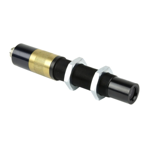
If you have an LDM127G Model (see drawing A) follow the method below:
1. Insert focus key (see drawing C) into laser barrel and align with focus control groves.
2. Turn the focus key until desired focus is achieved.
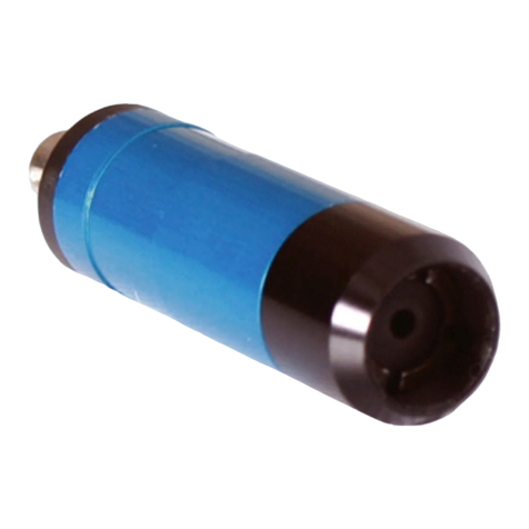
If you have an LDM127P Model (see drawing B) follow the method below.
1. Taking care not to touch the lens itself, grip the forward section of the laser.
2. Turn until the beam is the desired size.
