OPTIMUM Maschinen OPTidrill DH 40CT User manual

GB
Operating Manual
Version 1.0.2
Gearbox drilling milling machine
Part no. 3034351
Part no. 3034350
DH40CTP
DH40CT

Version 1.0.2 - 2020-07-062 Translation of original instruction
DH 40CT | DH 40CTP
EN
DH40CT_DH40CTP_GBIVZ.fm
Table of contents
1 Safety
1.1 Rating plate.................................................................................................................................................... 6
1.1.1 Machine variants.............................................................................................................................. 6
1.2 Safety instructions (warning notes)................................................................................................................ 7
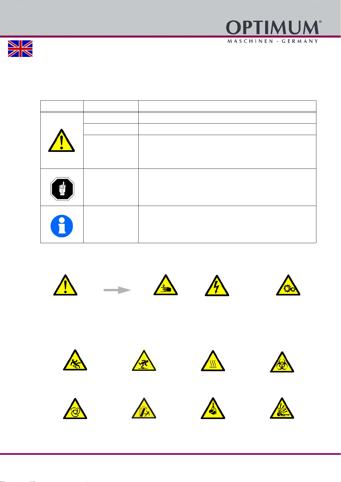
1.2.1 Classification of hazards.................................................................................................................. 7
1.2.2 Other pictograms.............................................................................................................................. 7
1.3 Intended use.................................................................................................................................................. 8
1.4 Reasonably foreseeable misuse.................................................................................................................... 9
1.4.1 Avoiding misuse............................................................................................................................... 9
1.5 Possible dangers posed by the drilling milling machine ................................................................................ 9
1.6 Qualification of personnel............................................................................................................................ 10
1.6.1 Target group................................................................................................................................... 10
1.6.2 Authorized persons........................................................................................................................ 11
1.7 Operator positions ....................................................................................................................................... 12
1.8 Safety measures during operation............................................................................................................... 12
1.9 Safety devices ............................................................................................................................................. 12
1.9.1 Emergency stop button.................................................................................................................. 13
1.9.2 Protective cover ............................................................................................................................. 13
1.9.3 Main switch .................................................................................................................................... 13
1.9.4 Cross table..................................................................................................................................... 13
1.9.5 Drilling milling guard....................................................................................................................... 13
1.9.6 Prohibition, warning and mandatory signs..................................................................................... 13
1.10 Safety check................................................................................................................................................ 14
1.11 Personal protective equipment.................................................................................................................... 14
1.12 Safety during operation................................................................................................................................ 15
1.13 Safety during maintenance.......................................................................................................................... 15
1.13.1 Switching-off and securing the drilling milling machine.................................................................. 15
1.14 Using lifting equipment ................................................................................................................................ 16
1.14.1 Mechanical maintenance ............................................................................................................... 16
1.15 Accident report............................................................................................................................................. 16
1.16 Electronics................................................................................................................................................... 16
1.17 Inspection deadlines.................................................................................................................................... 17
2 Technical data
2.1 Electrical connection.................................................................................................................................... 18
2.2 Drilling capacity / milling capacity................................................................................................................ 18
2.3 Spindle head................................................................................................................................................ 18
2.4 Cross table................................................................................................................................................... 18
2.5 Dimensions.................................................................................................................................................. 18
2.11 Emissions .................................................................................................................................................... 19
2.6 Work area.................................................................................................................................................... 19
2.7 Speeds......................................................................................................................................................... 19
2.8 Spindle quill feed ......................................................................................................................................... 19
2.9 Environmental conditions............................................................................................................................. 19
2.10 Operating material....................................................................................................................................... 19
2.12 Installation plan DH 40CT | DH40CTP ........................................................................................................ 20
3 Delivery, interdepartmental transport, assembly and commissioning
3.1 Notes on transport, installation, commissioning .......................................................................................... 21
3.1.1 General risks during internal transport........................................................................................... 21
3.2 Unpacking the machine............................................................................................................................... 22
3.3 Scope of delivery......................................................................................................................................... 22
3.3.1 Accessories.................................................................................................................................... 22
3.4 Installation and assembly ............................................................................................................................ 22
3.4.1 Requirements regarding the installation site.................................................................................. 22
3.4.2 Load suspension point................................................................................................................... 22
3.4.3 Assembly........................................................................................................................................ 23
3.4.4 Installation...................................................................................................................................... 23

Version 1.0.2 - 2020-07-06 3Translation of original instruction
DH 40CT | DH 40CTP EN
DH40CT_DH40CTP_GBIVZ.fm
3.4.5 Fixing..............................................................................................................................................23
3.5 Lubrication....................................................................................................................................................24
3.6 First commissioning......................................................................................................................................24
3.6.1 Warming up the machine................................................................................................................24
3.6.2 Power supply ..................................................................................................................................24
3.6.3 Checks............................................................................................................................................25
4Operation
4.1 Control and indicating elements...................................................................................................................26
4.1.1 DH40 CTP spindle sleeve feed.......................................................................................................27
4.2 Safety...........................................................................................................................................................27
4.3 Switching on the machine ............................................................................................................................27
4.3.1 Switching off the machine...............................................................................................................28
4.4 Feed for milling.............................................................................................................................................28
4.5 Speed setting ...............................................................................................................................................28
4.5.1 Selecting the speed........................................................................................................................28
4.5.2 Gear selector switch.......................................................................................................................28
4.6 Switching off the drilling milling machine......................................................................................................29
4.7 Drill depth stop .............................................................................................................................................29
4.8 Spindle sleeve feed with DH40CT................................................................................................................29
4.8.1 Manual spindle sleeve feed with the fine feed................................................................................29
4.8.2 Manual spindle sleeve feed with the spindle sleeve lever ..............................................................29
4.8.3 Quill clamping lever ........................................................................................................................30
4.9 Spindle sleeve feed with DH40CTP .............................................................................................................30
4.9.1 Automatic sleeve feed with DH40 CTP...........................................................................................30
4.9.2 Spindle sleeve feed with the manually fine feed.............................................................................31
4.10 Spindle head ................................................................................................................................................32
4.10.1 Swivelling the spindle head ............................................................................................................32
4.10.2 Turning the spindle head................................................................................................................32
4.10.3 Lifting and lowering the spindle head .............................................................................................33
4.11 Tool holder ...................................................................................................................................................33
4.11.1 Fitting the drill chuck.......................................................................................................................33
4.11.2 Unfitting the drill chuck....................................................................................................................33
4.11.3 Installation of milling tools...............................................................................................................33
4.11.4 Removing milling tools....................................................................................................................34
4.11.5 Use of collets..................................................................................................................................34
4.12 Cross table...................................................................................................................................................34
4.12.1 Adjusting the height of the cross table............................................................................................34
4.13 Drilling / tapping mode of operation..............................................................................................................34
4.14 Clamping the workpieces.............................................................................................................................35
4.14.1 Calculation of the Cutting Forces or Necessary Holding Force when Milling .................................35
4.15 Cooling.........................................................................................................................................................36
4.15.1 Coolant ...........................................................................................................................................36
5 Maintenance
5.1 Safety...........................................................................................................................................................37
5.1.1 Preparation.....................................................................................................................................37
5.1.2 Restarting .......................................................................................................................................38
5.2 Inspection and maintenance ........................................................................................................................38
5.3 Repair...........................................................................................................................................................41
5.3.1 Customer service technician...........................................................................................................41
6 Determining the cutting speed and the speed
6.1 Table cutting speeds / infeed .......................................................................................................................42
6.2 Speed table..................................................................................................................................................42
6.3 Examples to calculatory determine the required speed for your drilling machine ........................................44
6.4 Spindelkopf - Drilling head - DH40 CT .........................................................................................................45
6.4.1 Ersatzteilliste Spindelkopf - Spare part list drilling head - DH40 CT...............................................46
6.5 Spindelkopf - Drilling head - DH40 CTP.......................................................................................................49
6.5.1 Ersatzteilliste Spindelkopf - Spare part list drilling head - DH40 CTP ............................................50
6.6 Pinolenvorschub - Spindle sleeve feed - DH40 CTP....................................................................................53

Version 1.0.2 - 2020-07-064 Translation of original instruction
DH 40CT | DH 40CTP
EN
DH40CT_DH40CTP_GBIVZ.fm
6.6.1 Ersatzteilliste Pinolenvorschub - Spare part list spindle sleeve feed - DH40 CTP......................... 54
6.7 Bohrfutterschutz - Drilling chuck protection................................................................................................. 56
6.7.1 Schaltbox - Switch box................................................................................................................... 57
6.7.2 Säule und Bohrtisch - Column and drilling table............................................................................58
6.7.3 Teileliste Säule und Bohrtisch - Parts list column, column and drilling table ................................. 59
6.8 Schaltplan - Wiring diagram......................................................................................................................... 61
6.8.1 Teileliste Elektrik - Parts list electrical components ....................................................................... 62
7 Malfunctions
8 Appendix
8.1 Copyright ..................................................................................................................................................... 67
8.2 Terminology/Glossary.................................................................................................................................. 67
8.3 Storage........................................................................................................................................................ 67
8.4 Liability claims/warranty............................................................................................................................... 68
8.5 Advice for disposal / Options of reuse:........................................................................................................ 68
8.5.1 Decommissioning........................................................................................................................... 69
8.5.2 Disposal of new device packaging................................................................................................. 69
8.5.3 Disposal of the old device.............................................................................................................. 69
8.5.4 Disposal of electrical and electronic components.......................................................................... 69
8.5.5 Disposal of lubricants and coolants................................................................................................ 70
8.6 Disposal through municipal collection facilities............................................................................................ 70
8.7 Change information operating manual......................................................................................................... 70
8.8 Product follow-up......................................................................................................................................... 70

Version 1.0.2 - 2020-07-06 5Originalbetriebsanleitung
DH 40CT | DH 40CTP GB
_preface_GB.fm
Preface
Dear customer,
Thank you very much for purchasing a product made by OPTIMUM.
OPTIMUM metal working machines offer a maximum of quality, technically optimum solutions and convince
by an outstanding price performance ratio. Continuous enhancements and product innovations guarantee
state-of-the-art products and safety at any time.
Before commissioning the machine please thoroughly read these operating instructions and get familiar with
the machine. Please also make sure that all persons operating the machine have read and understood the
operating instructions beforehand.
Keep these operating instructions in a safe place nearby the machine.
Information
The operating instructions include indications for safety-relevant and proper installation, operation and main-
tenance of the machine. The continuous observance of all notes included in this manual guarantee the safety
of persons and of the machine.
The manual determines the intended use of the machine and includes all necessary information for its eco-
nomic operation as well as its long service life.
In the paragraph "Maintenance" all maintenance works and functional tests are described which the operator
must perform in regular intervals.
The illustration and information included in the present manual can possibly deviate from the current state of
construction of your machine. Being the manufacturer we are continuously seeking for improvements and
renewal of the products. Therefore, changes might be performed without prior notice. The illustrations of the
machine may be different from the illustrations in these instructions with regard to a few details. However,
this does not have any influence on the operability of the machine.
Therefore, no claims may be derived from the indications and descriptions. Changes and errors are reserved!
Your suggestion with regard to these operating instructions are an important contribution to optimising our
work which we offer to our customers. For any questions or suggestions for improvement, please do not hesi-
tate to contact our service department.
If you have any further questions after reading these operating instructions and you are not able to
solve your problem with a help of these operating instructions, please contact your specialised
dealer or directly the company OPTIMUM.
Optimum Maschinen Germany GmbH
Dr.- Robert - Pfleger - Str. 26
D-96103 Hallstadt
Fax (+49)0951 / 96555 - 888
Email: info@optimum-maschinen.de
Internet: www.optimum-machines.com

Safety
Version 1.0.2 - 2020-07-066 Translation of original instruction
DH 40CT | DH 40CTP
EN
DH40CT_DH40CTP_GB_1.fm
1 Safety
Glossary of symbols
This part of the operating instructions
explains the meaning and use of the warning notes included in these operating instructions,
defines the intended use of the drilling milling machine,
points out the dangers that might arise for you or others if these instructions are not
observed,
informs you about how to avoid dangers.
In addition to these operating instructions, please observe
the applicable laws and regulations,
the statutory provisions for accident prevention,
the prohibition, warning and mandatory signs as well as the warning notes on the drilling
milling machine.
Always keep this documentation close to the drilling milling machine.
INFORMATION
If you are unable to rectify an issue using these operating instructions, please contact us for
advice:
Optimum Maschinen Germany GmbH
Dr.-Robert-Pfleger-Str. 26
D-96103 Hallstadt
email: info@optimum-maschinen.de
1.1 Rating plate
1.1.1 Machine variants
DH40CT - Drilling milling machine without automatic spindle sleeve feed.
DH40CTP - Drilling milling machine with automatic spindle sleeve feed.
provides further instructions
calls on you to act
listings
Master Labels
Optimum Maschinen
Germany GmbH
Dr.-Robert-Pfleger-Str. 26
D-96103 Hallstadt
3034350
360 kg
1,1 / 1,5 kW
400 V ~50 Hz
DH 40CT
3200 U/min
20
NO.
SN
Year
optimum-maschinen.de
EN
FR
ES
IT
CS
D A
EL
FI
H U
NL
PL
PT
R O
R U
SK
SL
SV Pelarborrmaskin
TR
DE Säulenbohrmaschine
Upright drilling machine
Perceuse à colonne
Taladro
Trapano a colonna
Sloupová vrtačka
Søjleboremaskine
Επιδαπεδειο Δραπανο
Pylväsporakone
Asztali fúrógép
Kolomboormachine
Wiertarka kolumnowa
Máquina de perfuração
Mașină de găurit cu coloană
Станок вертикальный сверлильный
Steberni vrtalni stroj
Sütunlu Matkap
Stĺpová vŕtačka
5I[\MZ4IJMT[
7X\QU]U5I[KPQVMV
/MZUIVa/UJ0
,Z:WJMZ\8NTMOMZ;\Z
,!0ITT[\IL\
LH
L8
7_)[
%)$51
6NJO
67
;6
AMIZ
RSWLPXPPDVFKLQHQGH
&/
'3
&4
*5
$4
% "
&-
'*
) 6
/-
1-
15
3 0
3 6
4,
4-
471FMBSCPSSNBTLJO
53
%&4ÊVMFOCPISNBTDIJOF
6QSJHIUESJMMJOHNBDIJOF
1FSDFVTFËDPMPOOF
5BMBESP
5SBQBOPBDPMPOOB
4MPVQPWÈWSUBǏLB
4KMFCPSFNBTLJOF
ȝƇɂȽȺƇȾȽȾɂɈȜɉȺƇȺɆɈ
1ZMWÊTQPSBLPOF
"T[UBMJGÞSØHÏQ
,PMPNCPPSNBDIJOF
8JFSUBSLBLPMVNOPXB
.ÈRVJOBEFQFSGVSBÎÍP
.BǷJONJEFHNJVSJUDVDPMPBONJ
ʇʨʖʣʤʠʘʛʦʨʞʠʖʡʲʣʱʟʧʘʛʦʡʞʡʲʣʱʟ
4UFCFSOJWSUBMOJTUSPK
4àUVOMV.BULBQ
4UǤQPWÈWDZUBǏLB

Safety
Version 1.0.2 - 2020-07-06 7Translation of original instruction
DH 40CT | DH 40CTP EN
DH40CT_DH40CTP_GB_1.fm
1.2 Safety instructions (warning notes)
1.2.1 Classification of hazards
We classify the safety warnings into different categories. The table below gives an overview of
the classification of symbols (ideogram) and the warning signs for each specific danger and its
(possible) consequences.
1.2.2 Other pictograms
Symbol Alarm expression Definition / consequence
DANGER! Impending danger that will cause serious injury or death to people.
WARNING! A danger that can cause serious injury or death.
CAUTION!
A danger or unsafe procedure that can cause personal injury or damage to
property.
ATTENTION!
Situation that could cause damage to the drilling milling machine and
product, as well as other types of damage.
No risk of injury to persons.
Information
Practical tips and other important or useful information and notes.
No dangerous or harmful consequences for people or objects.
In case of specific dangers, we replace the pictogram with
or
general danger with a warning of injury to hands, hazardous
electrical voltage, rotating parts.
Warning: danger of
slipping! Warning: risk of stumbling! Warning: hot surface! Warning: biological hazard!
Warning: automatic start-
up! Warning: tilting danger! Warning: suspended loads! Caution, danger of
explosive substances!

Safety
Version 1.0.2 - 2020-07-068 Translation of original instruction
DH 40CT | DH 40CTP
EN
DH40CT_DH40CTP_GB_1.fm
1.3 Intended use
WARNING!
In the event of improper use, the drilling milling machine
will endanger personnel,
will endanger the machine and other material property of the operating company,
the functionality of the drilling milling machine may be compromised.
The drilling milling machine is designed and manufactured for holes in cold metals or other non
flammable materials or that not constitute a health hazard using a rotating filing-stripping tool
that has a number of grooves for collecting the filings.
If the drilling milling machine is used in any way other than described above, or modified with-
out the approval of Maschinen Germany GmbH, then the drilling milling machine is being used
improperly.
We will not be held liable for any damages resulting from any operation which is not in accord-
ance with the intended use.
We expressly point out that the guarantee will expire, if any constructive, technical or proce-
dural changes are not performed by the company Optimum Maschinen Germany GmbH.
It is also part of the intended use that you
observe the limits of the drilling milling machine,
the operating manual is observed,
the inspection and maintenance instructions are observed.
Technical data on page 18
WARNING!
Extremely severe injuries.
It is forbidden to make any modifications or alternations to the operation values of the
drilling milling machine. They could pose an accident hazard to persons and cause
damage to the drilling milling machine.
Switching on forbidden! Use ear protection! Read the operating
instructions before
commissioning!
Pull out the mains plug!
Wear protective glasses! Wear protective gloves! Wear safety shoes! Wear a protective suit!

Safety
Version 1.0.2 - 2020-07-06 9Translation of original instruction
DH 40CT | DH 40CTP EN
DH40CT_DH40CTP_GB_1.fm
1.4 Reasonably foreseeable misuse
Any use other than that specified under "Intended use" or any use beyond that described will be
deemed non-intended use and is not permissible.
Any other use must be discussed with the manufacturer.
It is only allowed to process metal, cold and non-inflammable materials with the drilling- milling
machine.
In order to avoid misuse, it is necessary to read and understand the operating instructions
before first commissioning.
Operators must be qualified.
1.4.1 Avoiding misuse
Use of suitable cutting tools.
Adapting the speed setting and feed to the material and workpiece.
Clamp workpieces firmly and free of vibration.
ATTENTION!
The workpiece is always to be fixed by a machine vice, jaw chuck or by another
appropriate clamping tool such as for the clamping claws.
WARNING!
Risk of injury caused by flying workpieces.
Clamp the workpiece in the machine vice. Make sure that the workpiece is firmly clamped in
the machine vice and that the machine vice is firmly clamped onto the machine table.
Use cooling and lubricating agents to increase the durability of the tool and to improve the
surface quality.
Clamp the cutting tools and workpieces on clean clamping surfaces.
Sufficiently lubricate the machine.
Set the bearing clearance and guides correctly.
Recommendations:
Insert the drill in a way that it is positioned exactly between the three clamping jaws of the
drill chuck.
When drilling, make sure that
the suitable speed is set depending on the diameter of the drill,
the pressure must only be such that the drill can cut without load,
if there is too much pressure, the drill will wear quickly and may even break or jam in the
borehole. If the drill gets jammed immediately stop the main motor by pressing the emer-
gency stop button,
For hard materials, e.g. steel, it is necessary to use commercial cooling/lubricating
agents.Basically, always pull out the drill with rotating spindle from the workpiece.
1.5 Possible dangers posed by the drilling milling machine
The drilling milling machine was built using state-of-the-art technology.
Nevertheless, there is a residual risk, as the drilling milling machine operates with
high speeds,
rotating parts,
electrical voltage and currents.
We have used design and safety engineering to minimize the health risk to personnel resulting
from these hazards.
If the drilling milling machine is used and maintained by personnel who are not duly qualified,
there may be a risk resulting from its incorrect or unsuitable maintenance.

Safety
Version 1.0.2 - 2020-07-0610 Translation of original instruction
DH 40CT | DH 40CTP
EN
DH40CT_DH40CTP_GB_1.fm
INFORMATION
Everyone involved in the assembly, commissioning, operation and maintenance must
be duly qualified,
and strictly follow these operating instructions.
In the event of improper use
there may be a risk to personnel,
there may be a risk to the machine and other material values,
the functionality of the drilling milling machine may be compromised.
Always disconnect the drilling milling machine, when cleaning or maintenance work is being
carried out.
WARNING!
The drilling milling machine may only be used with fully functional safety devices.
Disconnect the drilling milling machine immediately, whenever you detect a failure in the
safety devices or when they are not fitted!
All additional devices installed by the operator must be equipped with the stipulated
safety devices.
This is your responsibility being the operating company! Safety devices on page 12
CAUTION!
The drilling and milling machine DH40 CTP is equipped with an automatic quill feed. The
higher the speed at the quill, the higher the automatic feed.
1.6 Qualification of personnel
1.6.1 Target group
This manual is addressed to
the operating companies,
the operators,
the maintenance personnel.
Consequently, the warning notes refer both to the use of the drilling milling machine and to its
maintenance.
Determine clearly and explicitly who will be responsible for the different activities on the
machine (operation, setting up, maintenance and repair).
Unclear responsibilities constitute a safety risk!
Always lock the main switch after switching off the drilling milling machine. This will prevent it
from being used by unauthorized persons.
INFORMATION
Unclear responsibilities constitute a safety risk!
The qualifications of the personnel for the different tasks are mentioned below:
Operator
The operator has been instructed by the operating company regarding the assigned tasks and
possible risks in case of improper behaviour. Any tasks which need to be performed beyond the
operation in standard mode must only be performed by the operator, if so indicated in these
instructions and if the operator has been expressively commissioned by the operating com-
pany.

Safety
Version 1.0.2 - 2020-07-06 11Translation of original instruction
DH 40CT | DH 40CTP EN
DH40CT_DH40CTP_GB_1.fm
Qualified electrician
With professional training, knowledge and experience as well as knowledge of respective
standards and regulations, qualified electricians are able to perform work on the electrical sys-
tem and recognise and avoid any possible dangers.
Qualified electricians have been specially trained for the working environment, in which they are
working and know the relevant standards and regulations.
Qualified personnel
Due to their professional training, knowledge and experience as well as knowledge of relevant
regulations, qualified personnel are able to perform the assigned tasks and to independently
recognise and avoid any possible dangers.
Instructed person
Instructed persons were instructed by the operating company regarding the assigned tasks and
any possible risks of improper behaviour.
1.6.2 Authorized persons
WARNING!
Inappropriate operation and maintenance of the drilling milling machine constitutes a
danger to the personnel, objects and the environment.
Only authorized personnel may operate the drilling milling machine !
Authorized operating and maintenance personnel are specialists instructed and trained by the
operator and the manufacturer.
The operating company must
Obligations of the
operating
company
train the personnel,
instruct the personnel in regular intervals (at least once a year) on
- all safety regulations relevant to the machine,
- its operation and
- generally accepted engineering standards.
check the personnel‘s knowledge level,
document the training/instruction,
have attendance at the training/instruction confirmed by signature and
check whether the personnel is working safety and risk-conscious and observes the operat-
ing instructions.
Define and document the machine inspection deadlines in accordance with section 3 of the
Factory Safety Order and perform an operational risk analysis in accordance with section 6
of the Safety at Work Act.
The operator must
Obligations of the
operator
have obtained a training regarding the handling of the drilling milling machine,
know the function and mode of action,
before taking the machine in operation
- have read and understood the operating manual,
- be familiar with all safety devices and instructions. Additional
requirements
regarding the
qualification
Additional requirements apply for work on the following machine components:
Electric components or operating materials: Must only be worked on by a qualified electri-
cian or person working under the instructions and supervision of a qualified electrician.
Before starting work on electrical parts or operating agents, the following actions must be taken
in the order given:
disconnect all poles,

Safety
Version 1.0.2 - 2020-07-0612 Translation of original instruction
DH 40CT | DH 40CTP
EN
DH40CT_DH40CTP_GB_1.fm
secure against restarting,
check that there is no voltage.
1.7 Operator positions
The user position is in front of the drilling milling machine.
INFORMATION
The power plug of the drilling milling machine must be readily accessible.
1.8 Safety measures during operation
CAUTION!
Danger due to inhaling dust and mist that are hazardous to health.
Depending on the materials to be machined and the agents used, dusts and mists can
arise that are detrimental to health.
Ensure that the harmful dust and mist generated are safely sucked off at the point of
origin and routed away from the working area or filtered. To do so, use a suitable
extraction unit.
CAUTION!
Risk of fire and explosion by using flammable materials or cooling lubricants.
Extra precautionary measures must be taken before machining flammable materials (e.g.
aluminium, magnesium) or using combustible agents (e.g. spirit) to avert a health
hazard.
1.9 Safety devices
The drilling milling machine must only be operated with fully functional safety devices.
Stop the drilling milling machine immediately if there is a failure on the safety device or
becomes ineffective.
It is your responsibility!
If a safety device has been activated or has failed, the drilling milling machine must only be
used if you
the cause of the fault has been eliminated,
you have verified that there is no danger to personnel or objects.
WARNING!
If you bypass, remove or override a safety device in any other way, you are endangering
yourself and other persons working with the drilling milling machine. The possible
consequences are:
injuries due to components or workpieces flying off at high speed,
contact with rotating parts and
fatal electrocution.
WARNING!
Although the isolating safety devices provided and delivered with the machine are
designed to reduce the risks of workpieces being ejected or parts of tools or work-
pieces breaking off, they cannot eliminate these risks completely.
The drilling milling machine features the following safety devices:
An emergency stop push button,
a lockable main switch,
a drilling table, milling table with T-slots to fix the workpiece or a vice,

Safety
Version 1.0.2 - 2020-07-06 13Translation of original instruction
DH 40CT | DH 40CTP EN
DH40CT_DH40CTP_GB_1.fm
an adjustable spindle guard with position switch.
1.9.1 Emergency stop button
The drilling milling machine is equipped with an emergency stop button.
1.9.2 Protective cover
The spindle head is equipped with a pro-
tective cover.
WARNING!
Only remove the protective cover
when the mains plug of the drilling
milling machine is disconnected.
Img.1-1: Protective cover
1.9.3 Main switch
In the "0" position, the lockable master switch can be secured against accidental or non-author-
ised switching on by means of a padlock.
When the master switch is switched off, the power supply to the machine is completely inter-
rupted.
Except for the areas marked by the pictogram in the margin. In these areas there might be volt-
age, even if the master switch is switched-off.
1.9.4 Cross table
Seats for T-slots are attached to the cross table.
WARNING!
Risk of injury due to workpieces flying off at high speed. Securely fix the workpiece on
the drilling table.
1.9.5 Drilling milling guard
Set the chuck guard to the required
height.
Close the drilling milling guard before
you start milling or drilling.
The drilling milling machine can only be
switched on if the guard is closed.
Img.1-2: Spindle guard
1.9.6 Prohibition, warning and mandatory signs
INFORMATION
All warning signs must be legible. They must be checked regularly.
Protective cover
Drill chuck guard

Safety
Version 1.0.2 - 2020-07-0614 Translation of original instruction
DH 40CT | DH 40CTP
EN
DH40CT_DH40CTP_GB_1.fm
1.10 Safety check
Check the drilling milling machine at least once per shift. Inform the person responsible immedi-
ately of any damage, defects or changes in the operating function.
Check all safety devices
at the beginning of each shift (with the machine stopped),
once a week (with the machine in operation) and
after all maintenance and repair work.
Check that prohibition, warning and information signs and the labels on the drilling milling
machine
are legible (clean them, if necessary)
are complete.
INFORMATION
Organise the checks according to the following table;
1.11 Personal protective equipment
For some works you need personnel protective equipment as protective equipment. These are
Safety helmet,
protective glasses or face guard,
protective gloves,
safety shoes with steel toe caps,
ear protection.
hairnet.
Before starting work make sure that the required personnel protective equipment is available at
the work place.
CAUTION!
Dirty or contaminated personnel protective equipment can cause illness.
General check
Equipment Check OK
Guards Mounted, firmly bolted and not damaged
Drill chuck guard
Signs,
Markers Installed and legible
Date: Checked by (signature):
Functional check
Equipment Check OK
Emergency-stop
pushbutton After actuating an emergency stop push button the drilling
milling machine must be switched off.
Spindle guard The drilling milling machine can only be switched on if the
guard is closed.
Date: Checked by (signature):

Safety
Version 1.0.2 - 2020-07-06 15Translation of original instruction
DH 40CT | DH 40CTP EN
DH40CT_DH40CTP_GB_1.fm
Clean your personal protective equipment
after each use,
regularly once a week.
Personal protective equipment for special works
Wear protective gloves when handling pieces or tools with sharp edges.
Wear safety shoes when you assemble, disassemble or transport heavy components.
Use ear protectors if the noise level (emission) in the workplace exceeds 80 dB (A).
Protect your face and your eyes: Wear a safety helmet with facial protection when performing
work where your face and eyes are exposed to hazards.
Before starting work make sure that the required personal protective equipment is available at
the work place.
1.12 Safety during operation
We specifically point out the dangers in the description of work with and on the drilling milling
machine.
WARNING!
Before switching on the drilling milling machine make sure that there are no
lead to any danger with respect to people,
cause any damage to equipment.
Avoid any unsafe work methods:
Make sure that your operation does not create a safety hazard.
The rules specified in these operating instructions must be observed during assembly,
operation, maintenance and repair.
Do not work on the drilling milling machine, if your concentration is reduced, for example,
because you are taking medication.
Observe the accident prevention regulations issued by your Employers Liability Insurance
Association or other supervisory authorities applicable to your company.
Inform the supervisor about all hazards or faults.
Stay at the drilling milling machine until the movements have stopped completely.
Use the specified personal protective equipment. Ensure you wear close-fitting clothing
and, if necessary, a hairnet.
Do not use protective gloves when drilling.
1.13 Safety during maintenance
Inform the operators in good time of any maintenance and repair works.
Report all safety relevant changes and performance details of the drilling milling machine or
their operational behaviour. Any changes must be documented, the operating instructions
updated and machine operators instructed accordingly.
1.13.1 Switching-off and securing the drilling milling machine
Switch off the machine by turning off the master switch before starting any maintenance and
repair work.
Use a padlock to prevent the switch from being turned on without authorization and keep the
key in a safe place.
All machine parts as well as all dangerous voltages are switched off. Excepted are only the
positions which are marked with the adjoining pictogram.
Attach a warning sign to the machine.

Safety
Version 1.0.2 - 2020-07-0616 Translation of original instruction
DH 40CT | DH 40CTP
EN
DH40CT_DH40CTP_GB_1.fm
1.14 Using lifting equipment
WARNING!
The use of unstable lifting and load suspension equipment that might break under load
can cause severe injuries or even death.
Check that the lifting and load suspension gear
they have sufficient load carrying,
and that it is in perfect condition.
Observe the accident prevention regulations issued by your Employers Liability
Insurance Association or other supervisory authorities applicable to your company.
Fasten the loads carefully. Never walk under suspended loads!
1.14.1 Mechanical maintenance
Remove or install protection safety devices before starting or after completing any mainte-
nance work; this include:
covers,
safety instructions and warning signs,
grounding cables.
If you remove protective or safety devices, re-fit them immediately after the completing the
work. Check if they are working properly!
1.15 Accident report
Inform your supervisors and Optimum Maschinen Germany GmbH immediately in the event of
accidents, possible sources of danger and any actions which almost led to an accident (near
misses).
There are many possible causes for "near misses".
The sooner they are notified, the quicker the causes can be eliminated.
1.16 Electronics
Have the machine and/or the electric equipment checked regularly. Immediately eliminate all
defects such as loose connections, defective wires, etc.
A second person must be present during work on live components to disconnect the power in
the event of an emergency. Disconnect the machine immediately if there is a malfunction in the
power supply!
Comply with the required inspection intervals in accordance with the factory safety directive,
operating equipment inspection DGUV, formerly BVG.
The operating company responsible for the machine must ensure that the electrical systems
and operating equipment are inspected with regards to their proper condition, namely,
by a qualified electrician or under the supervision and direction of a qualified electrician,
prior to initial commissioning and after modifications or repairs, prior to recommissioning
and at set intervals.
The intervals must be set so that foreseeable defects can be detected in a timely manner, when
they occur.
The relevant electro-technical rules must be followed during the inspection.
The inspection prior to initial commissioning is not required if the operator receives confirma-
tion from the manufacturer or installer that the electrical systems and operating equipment com-
ply with the accident prevention regulations, see conformity declaration.
Permanently installed electrical systems and operating equipment are considered constantly
monitored if they are continually serviced by qualified electricians and inspected by means of
measurements in the scope of operation (e.g. monitoring the insulation resistance).

Safety
Version 1.0.2 - 2020-07-06 17Translation of original instruction
DH 40CT | DH 40CTP EN
DH40CT_DH40CTP_GB_1.fm
1.17 Inspection deadlines
Define and document the inspection deadlines for the machine in accordance with § 3 of the
Factory Safety Act and perform an operational risk analysis in accordance with § 6 of the Work
Safety Act. The inspection intervals in the maintenance section should be used as reference
values.

Technical data
Version 1.0.2 - 2020-07-0618 Translation of original instruction
DH 40CT | DH 40CTP
EN
DH40CT_DH40CTP_GB_2.fm
2 Technical data
The following information represents the dimensions and indications of weight and the manu-
facturer‘s approved machine data.
2.1 Electrical connection DH40 CT DH40 CTP
Connection 3 x 400V ~ 50Hz ( 60Hz )
Fusing performed by the operator 16 A
Operating mode, duty cycle S6 - 60%
2.2 Drilling capacity / milling capacity
Spindle drive power, 2-stage drive motor
Star-delta connection 1.1 / 1.5 kW
Drilling capacity in steel [mm] 32
Continuous drilling capacity in steel [mm] 28
Max. milling head size [ mm] 76
Max. end mill cutter size [ mm] 25
2.3 Spindle head
Spindle sleeve stroke [mm] 120
Spindle seat MT4
Spindle head 360 ° rotatable, 45 ° swiveling
Adjustable in height 260mm
Throat [mm] 280
Distance to machine base [mm] 920 to 1180
Distance to cross table [mm] 0 until 600
2.4 Cross table
Table size Length x Width [mm] 210 x 730
T-slot size / distance / number 14mm / 63 / 3
X axis travel [mm] 480
Y axis travel [mm] 180
Z axis travel [mm] 560
Cross table, max. bearing load 50kg
2.5 Dimensions Installation plan DH 40CT | DH40CTP on page 20
Total weight [kg] 350
Column diameter [mm] 115
+Z
+Y
+X

Technical data
Version 1.0.2 - 2020-07-06 19Translation of original instruction
DH 40CT | DH 40CTP EN
DH40CT_DH40CTP_GB_2.fm
2.11 Emissions
The noise emission of the drilling milling machine is 76 to 78 dB(A).
INFORMATION
This numerical value was measured on a new machine under the operating conditions specified
by the manufacturer. The noise behaviour of the machine might change depending on the age
and wear of the machine.
Furthermore, the noise emission also depends on production engineering factors, e.g. speed,
material and clamping conditions.
INFORMATION
The specified numerical value represents the emission level and does not necessarily a safe
working level.
Though there is a dependency between the degree of the noise emission and the degree of the
noise disturbance it is not possible to use it reliably to determine if further precaution measures
are required or not.
The following factors influence the actual degree of the noise exposure of the operator:
- Characteristics of the working area, e.g. size or damping behaviour,
- other noise sources, e.g. the number of machines,
- other processes taking place in proximity and the period of time, during which the opera-
tor is exposed to the noise.
Furthermore, it is possible that the admissible exposure level might be different from country to
country due to national regulations.
This information about the noise emission should, however, allow the operator of the machine
to more easily evaluate the hazards and risks.
2.6 Work area
Keep a work area of at least one metre around the machine
free for operation and maintenance.
2.7 Speeds
Spindle speeds [ rpm ] 95 - 3200
Number of steps 12
2.8 Spindle quill feed DH40 CT DH40 CTP
manual automatic
0.10 | 0.18 | 0.26 mm/rev
2.9 Environmental conditions
Temperature 5-35°C
Humidity 25 - 80 %
2.10 Operating material
Gear oil Mobilgear 627 or a comparable gear oil
about 3 liters
Toothed rod and drill column Commercial plain bearing grease
DH40 CTP spindle sleeve feed Machine oil

Technical data
Version 1.0.2 - 2020-07-0620 Translation of original instruction
DH 40CT | DH 40CTP
EN
DH40CT_DH40CTP_GB_2.fm
CAUTION!
Depending on the overall noise exposure and the basic threshold values, machine
operators must wear appropriate hearing protectors.
We generally recommend the use of noise and ear protection.
2.12 Installation plan DH 40CT | DH40CTP
Img.2-1: Dimensions
605
405
This manual suits for next models
3
Table of contents
Other OPTIMUM Maschinen Drill manuals

OPTIMUM Maschinen
OPTIMUM Maschinen OPTI drill B 17Pro User manual

OPTIMUM Maschinen
OPTIMUM Maschinen OPTidrill B17Pro basic User manual

OPTIMUM Maschinen
OPTIMUM Maschinen OPTidrill B 34H User manual

OPTIMUM Maschinen
OPTIMUM Maschinen OPTImill Bf 46Vario User manual

OPTIMUM Maschinen
OPTIMUM Maschinen OPTIdrill DH40G User manual