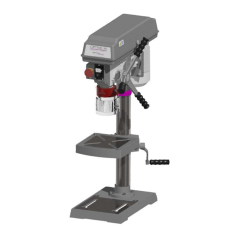
OPTIMUM Maschinen OPTI drill B 17Pro User manual

GB
OPTIMUM
MASCHINEN - GERMANY
®
Upright drilling machine
Operating Manual
Version 2.1.2
Bench drilling machine

Version 2.1.2 dated 2018-09-13Page 2 Original operating instructions
B17Pro | B23Pro | B26Pro | B33ProGB
OPTIMUM
MASCHINEN - GERMANY
®
Table of contents
1 Safety
1.1 Safety instructions (warning notes)...........................................................................................................8
1.1.1 Classification of hazards...........................................................................................................................8
1.1.2 Other pictograms ......................................................................................................................................8
1.2 Intended use .............................................................................................................................................9
1.3 Reasonably foreseeable misuse...............................................................................................................9
1.3.1 Avoiding misuse......................................................................................................................................10
1.4 Possible dangers caused by the drilling machine...................................................................................11
1.5 Qualification of personnel .......................................................................................................................12
1.5.1 Target group ...........................................................................................................................................12
1.5.2 Authorized personnel..............................................................................................................................12
1.6 Operator positions ..................................................................................................................................13
1.7 Safety measures during operation..........................................................................................................13
1.8 Safety devices ........................................................................................................................................13
1.9 EMERGENCY-STOP push button..........................................................................................................14
1.10 Separating protective devices.................................................................................................................14
1.10.1 Covering cap of the pulley ......................................................................................................................14
1.10.2 Drill chuck protection ..............................................................................................................................15
1.11 Drilling table ............................................................................................................................................15
1.12 Prohibition, warning and mandatory signs..............................................................................................15
1.13 Safety check ...........................................................................................................................................15
1.14 Personal protective equipment ...............................................................................................................16
1.15 Safety during operation...........................................................................................................................17
1.16 Safety during maintenance.....................................................................................................................17
1.16.1 Disconnecting and securing the drilling machine....................................................................................17
1.16.2 Using lifting equipment ...........................................................................................................................17
1.16.3 Mechanical maintenance work ...............................................................................................................18
1.17 Accident report........................................................................................................................................18
1.18 Electrical system.....................................................................................................................................18
2 Technical data
2.1 Electrical connection...............................................................................................................................19
2.2 Drive motor power ..................................................................................................................................19
2.3 Drilling capacity in steel S235JR ............................................................................................................19
2.4 Continuous drilling capacity in steel S235JR..........................................................................................19
2.5 Spindle seat ............................................................................................................................................19
2.6 T-slots - size ...........................................................................................................................................19
2.7 Table size ...............................................................................................................................................19
2.8 Spindle stroke .........................................................................................................................................19
2.9 Throat depth ...........................................................................................................................................19
2.10 Machine height .......................................................................................................................................19
2.11 Column diameter ....................................................................................................................................19
2.12 Distance spindle - drill table....................................................................................................................19
2.13 Distance spindle - machine base............................................................................................................19
2.14 Dimension...............................................................................................................................................19
2.18 Emissions ...............................................................................................................................................20
2.15 Weight of machine [kg] ...........................................................................................................................20
2.16 Spindle speeds .......................................................................................................................................20
2.17 Environmental conditions temperature ...................................................................................................20
3 Assembly
3.1 Scope of delivery ....................................................................................................................................21
3.2 Transport ................................................................................................................................................21

Version 2.1.2 dated 2018-09-13 Page 3Original operating instructions
B17Pro | B23Pro | B26Pro | B33Pro GB
OPTIMUM
MASCHINEN - GERMANY
®
3.3 Installation and assembly ....................................................................................................................... 22
3.3.1 Requirements regarding the installation site .......................................................................................... 22
3.3.2 Assembly................................................................................................................................................ 22
3.4 Installation .............................................................................................................................................. 25
3.4.1 Fixing...................................................................................................................................................... 25
3.5 First commissioning................................................................................................................................ 28
3.6 Electrical connection .............................................................................................................................. 29
3.6.1 Machines without a frequency converter................................................................................................ 29
3.6.2 Machines with frequency converter for speed control ............................................................................ 29
3.6.3 Warming up the machine ....................................................................................................................... 30
4Operation
4.1 Control and indicating elements ............................................................................................................. 31
4.2 Safety ..................................................................................................................................................... 32
4.2.1 Drill depth stop ....................................................................................................................................... 32
4.2.2 Inclination table ...................................................................................................................................... 32
4.3 Speed change ........................................................................................................................................ 33
4.3.1 Speed tables .......................................................................................................................................... 33
4.4 Standard values for speeds with HSS – Eco – twist drilling ...................................................................39
4.5 Switching on the machine ...................................................................................................................... 39
4.6 Switching off the machine ...................................................................................................................... 39
4.7 Quick-action drill chuck .......................................................................................................................... 39
4.7.1 Disassembly quick- action drill chuck..................................................................................................... 40
4.7.2 Assembly quick- action drill chuck.......................................................................................................... 40
4.8 Cooling ................................................................................................................................................... 40
4.9 Before starting work ............................................................................................................................... 40
4.10 During work ............................................................................................................................................ 41
5 Maintenance
5.1 Safety ..................................................................................................................................................... 42
5.1.1 Preparation............................................................................................................................................. 42
5.1.2 Restarting ............................................................................................................................................... 42
5.2 Inspection and Maintenance .................................................................................................................. 42
5.3 Repair..................................................................................................................................................... 45
5.3.1 Customer service technician .................................................................................................................. 45
6 Determining the cutting speed and the speed
6.1 Table cutting speeds / infeed ................................................................................................................. 46
6.2 Speed table ............................................................................................................................................ 46
6.3 Examples to calculatory determine the required speed for your drilling machine .................................. 48
7 Ersatzteile - Spare parts - B17Pro, B23Pro, B26Pro, B33Pro - (Vario)
7.1 OPTI B17Pro 1 - 2.................................................................................................................................. 49
7.2 OPTI B17Pro 2 - 2.................................................................................................................................. 50
7.3 B23Pro, B23Pro Vario 1 - 2.................................................................................................................... 54
7.4 B23Pro, B23Pro Vario 2- 2..................................................................................................................... 55
7.5 OPTI B26Pro, B26Pro Vario 1 - 2 .......................................................................................................... 58
7.6 OPTI B26Pro, B26Pro Vario 2- 2 ........................................................................................................... 59
7.7 B33Pro, B33Pro Vario 1 - 2.................................................................................................................... 62
7.8 B33Pro, B33Pro Vario 2- 2..................................................................................................................... 63
7.8.1 Bohrfutterschutz neuer Typ - Drill chuck protection new type ................................................................ 66
7.9 Maschinenschilder - Machine labels ...................................................................................................... 67
7.10 Schaltplan - Wiring diagram - B17Pro, B23Pro - 230V .......................................................................... 68
7.11 Schaltplan - Wiring diagram - B23Pro, B26Pro, B33Pro - 400 V ........................................................... 69
7.12 Schaltplan - Wiring diagram - B23Pro Vario, B26Pro Vario, B33Pro Vario ............................................ 70
8 Malfunctions
8.1 Malfunctions on the drilling machine ...................................................................................................... 71

Version 2.1.2 dated 2018-09-13Page 4 Original operating instructions
B17Pro | B23Pro | B26Pro | B33ProGB
OPTIMUM
MASCHINEN - GERMANY
®
9 Appendix
9.1 Copyright ................................................................................................................................................72
9.2 Terminology/Glossary.............................................................................................................................72
9.3 Change information operating manual....................................................................................................72
9.4 Liability claims for defects / warranty ......................................................................................................73
9.5 Storage ...................................................................................................................................................74
9.6 Advice for disposal / Options of re-use ...................................................................................................74
9.6.1 Decommissioning ...................................................................................................................................75
9.6.2 Disposal of new device packaging..........................................................................................................75
9.6.3 Disposing of the old device.....................................................................................................................75
9.6.4 Disposal of electrical and electronic components...................................................................................75
9.6.5 Disposal of lubricants and coolants ........................................................................................................76
9.7 Disposal via municipal collection facilities ..............................................................................................76
9.8 RoHS, 2011/65/EU .................................................................................................................................76
9.9 Product follow-up ....................................................................................................................................76

Version 2.1.2 2018-09-13 Page 5Translation of the original instructions
B17Pro | B23Pro | B26Pro | B33Pro GB
_preface_GB.fm
OPTIMUM
MASCHINEN - GERMANY
®
Preface
Dear customer,
Thank you very much for purchasing a product made by OPTIMUM.
OPTIMUM metal working machines offer a maximum of quality, technically optimum solutions
and convince by an outstanding price performance ratio. Continuous enhancements and prod-
uct innovations guarantee state-of-the-art products and safety at any time.
Before commissioning the machine please thoroughly read these operating instructions and get
familiar with the machine. Please also make sure that all persons operating the machine have
read and understood the operating instructions beforehand.
Keep these operating instructions in a safe place nearby the machine.
Information
The operating instructions include indications for safety-relevant and proper installation, opera-
tion and maintenance of the machine. The continuous observance of all notes included in this
manual guarantee the safety of persons and of the machine.
The manual determines the intended use of the machine and includes all necessary information
for its economic operation as well as its long service life.
In the paragraph "Maintenance" all maintenance works and functional tests are described which
the operator must perform in regular intervals.
The illustration and information included in the present manual can possibly deviate from the
current state of construction of your machine. Being the manufacturer we are continuously
seeking for improvements and renewal of the products. Therefore, changes might be performed
without prior notice. The illustrations of the machine may be different from the illustrations in
these instructions with regard to a few details. However, this does not have any influence on
the operability of the machine.
Therefore, no claims may be derived from the indications and descriptions. Changes and errors
are reserved!
Your suggestion with regard to these operating instructions are an important contribution to
optimising our work which we offer to our customers. For any questions or suggestions for
improvement, please do not hesitate to contact our service department.
If you have any further questions after reading these operating instructions and you are
not able to solve your problem with a help of these operating instructions, please con-
tact your specialised dealer or directly the company OPTIMUM.
Optimum Maschinen Germany GmbH
Dr.- Robert - Pfleger - Str. 26
D-96103 Hallstadt
Mail: info@optimum-maschinen.de
Internet: www.optimum-maschinen.com

Safety
Version 2.1.2 dated 2018-09-13Page 6 Translation of the original instructions
B17Pro | B23Pro | B26Pro | B33ProGB
B17_B23_B26_B33_GB_1.fm
OPTIMUM
MASCHINEN - GERMANY
®
1 Safety
Glossary of symbols
This part of the operating instructions
explains the meaning and use of the warning notes included in these operating instructions,
defines the intended use of the drilling machine,
points out the dangers that might arise for you or others if these instructions are not
observed,
informs you about how to avoid dangers.
In addition to these operation instructions, please observe
the applicable laws and regulations,
the statutory provisions for accident prevention,
the prohibition, warning and mandatory signs as well as the warning labels on the drilling
machine.
When installing, operating, maintaining and repairing the drilling machine it is necessary to
observe the European standards.
If European standards have not yet been incorporated in the national legislation of the country
of destination, the specific applicable regulations of each country must be observed.
If applicable, necessary measures must be taken to comply with the country-specific regula-
tions before commissioning the drilling machine.
Always keep this documentation close to the drilling machine.
INFORMATION
If you are unable to rectify an issue using these operating instructions, please contact us for
advice:
Optimum Maschinen Germany GmbH
Dr. Robert-Pfleger-Str. 26
D- 96103 Hallstadt
email: info@optimum-maschinen.de
provides further instructions
calls on you to act
enumerations

Safety
Version 2.1.2 dated 2018-09-13 Page 7Translation of the original instructions
B17Pro | B23Pro | B26Pro | B33Pro GB
B17_B23_B26_B33_GB_1.fm
OPTIMUM
MASCHINEN - GERMANY
®
Type plates
Optimum Maschinen
Germany GmbH
Dr.-Robert-Pfleger-Str. 26
D-96103 Hallstadt
300 3263
82 kg
750 W
400 V ~50 Hz
B 26 Pro
2440 U/min
20
NO.
SN
Year
Master Labels
J
DE
GB
ES
FR
IT
CZ
DK
FI
GR
HU
NL
PL
PT
RU
SLO
TR
Säulenbohrmaschine
Søjleboremaskine
Pylväsporakone
Wiertarki
Bormașină
Upright drilling machine
Taladro
Perceuse
Trapano a colonna
Sloupová vrtačka
Επιδαπεδειο Δραπανο
Asztali fúrógép
Boormachine
Máquina de perfuração
Steberni vrtalni stroj
Sütunlu Matkap
optimum-maschinen.de
Master Labels
Optimum Maschinen
Germany GmbH
Dr.-Robert-Pfleger-Str. 26
D-96103 Hallstadt
300 3231
66 kg
750 W
230 V ~50 Hz
B 23 Pro
2440 U/min
20
NO.
SN
Year
J
Tischbohrmaschine
Bench drilling machine
Taladro de sobremesa
Perceuse modèle établi
Trapani da banco
Stolní vrtačka
Table boremaskine
Penkkiporakone
Asztali fúrógép
Boormachine tafelmodel
Wiertarki
Engenho de Furarde Bancada
Masina de gaurit
Bänkborrmaskin
Namizni vrtalni stroj
Sütunlu Matkap
ΔΡΑΠΑΝΟ ΠΑΓΚΟΥ
DE
GB
ES
FR
IT
CZ
DK
FI
GR
HU
NL
PL
PT
RO
SE
SK
TR optimum-maschinen.de
Optimum Maschinen
Germany GmbH
Dr.-Robert-Pfleger-Str. 26
D-96103 Hallstadt
300 3171
39 kg
500 W
230 V ~50 Hz
B 17 Pro
2520 U/min
20
NO.
SN
Year
Master Labels
J
Tischbohrmaschine
Bench drilling machine
Taladro de sobremesa
Perceuse modèle établi
Trapani da banco
Stolní vrtačka
Table boremaskine
Penkkiporakone
Asztali fúrógép
Boormachine tafelmodel
Wiertarki
Engenho de Furarde Bancada
Masina de gaurit
Bänkborrmaskin
Namizni vrtalni stroj
Sütunlu Matkap
ΔΡΑΠΑΝΟ ΠΑΓΚΟΥ
DE
GB
ES
FR
IT
CZ
DK
FI
GR
HU
NL
PL
PT
RO
SE
SK
TR optimum-maschinen.de
Optimum Maschinen
Germany GmbH
Dr.-Robert-Pfleger-Str. 26
D-96103 Hallstadt
300 3333
135 kg
1,1 kW
400 V ~50 Hz
B 33 Pro
1810 U/min
20
NO.
SN
Year
Master Labels
DE
GB
ES
FR
IT
CZ
DK
FI
GR
HU
NL
PL
PT
RU
SLO
TR
Säulenbohrmaschine
Søjleboremaskine
Pylväsporakone
Wiertarki
Bormașină
Upright drilling machine
Taladro
Perceuse
Trapano a colonna
Sloupová vrtačka
Επιδαπεδειο Δραπανο
Asztali fúrógép
Boormachine
Máquina de perfuração
Steberni vrtalni stroj
Sütunlu Matkap optimum-maschinen.de
Optimum Maschinen
Germany GmbH
Dr.-Robert-Pfleger-Str. 26
D-96103 Hallstadt
301 1233
75 kg
750 W
400 V ~50 Hz
B 23 Pro Vario
4940 U/min
20
NO.
SN
Year
J
Master Labels
Tischbohrmaschine
Bench drilling machine
Taladro de sobremesa
Perceuse modèle établi
Trapani da banco
Stolní vrtačka
Table boremaskine
Penkkiporakone
Επιτραπέζιο Δραπανο
Asztali fúrógép
Boormachine tafelmodel
Wiertarki
Engenho de Furarde Bancada
Masina de gaurit
Bänkborrmaskin
Namizni vrtalni stroj
Sütunlu Matkap
DE
GB
ES
FR
IT
CZ
DK
FI
GR
HU
NL
PL
PT
RO
SE
SK
TR optimum-maschinen.de
Optimum Maschinen
Germany GmbH
Dr.-Robert-Pfleger-Str. 26
D-96103 Hallstadt
301 1333
140 kg
1,5 kW
400 V ~50 Hz
B 33 Pro Vario
3850 U/min
20
NO.
SN
Year
J
Master Labels
DE
GB
ES
FR
IT
CZ
DK
FI
GR
HU
NL
PL
PT
RU
SLO
TR
Säulenbohrmaschine
Søjleboremaskine
Pylväsporakone
Wiertarki
Bormașină
Upright drilling machine
Taladro
Perceuse
Trapano a colonna
Sloupová vrtačka
Επιδαπεδειο Δραπανο
Asztali fúrógép
Boormachine
Máquina de perfuração
Steberni vrtalni stroj
Sütunlu Matkap
optimum-maschinen.de
Optimum Maschinen
Germany GmbH
Dr.-Robert-Pfleger-Str. 26
D-96103 Hallstadt
301 1263
90 kg
750 W
400 V ~50 Hz
B 26 Pro Vario
4000 U/min
20
NO.
SN
Year
J
Master Labels
DE
GB
ES
FR
IT
CZ
DK
FI
GR
HU
NL
PL
PT
RU
SLO
TR
Säulenbohrmaschine
Søjleboremaskine
Pylväsporakone
Wiertarki
Bormașină
Upright drilling machine
Taladro
Perceuse
Trapano a colonna
Sloupová vrtačka
Επιδαπεδειο Δραπανο
Asztali fúrógép
Boormachine
Máquina de perfuração
Steberni vrtalni stroj
Sütunlu Matkap
optimum-maschinen.de

Safety
Version 2.1.2 dated 2018-09-13Page 8 Translation of the original instructions
B17Pro | B23Pro | B26Pro | B33ProGB
B17_B23_B26_B33_GB_1.fm
OPTIMUM
MASCHINEN - GERMANY
®
1.1 Safety instructions (warning notes)
1.1.1 Classification of hazards
We classify the safety warnings into different categories. The table below gives an overview of
the classification of symbols (ideogram) and the warning signs for each specific danger and its
(possible) consequences.
1.1.2 Other pictograms
Symbol Warning alert Definition / consequence
DANGER! Impending danger that will cause serious injury or death to people.
WARNING! A danger that can cause serious injury or death.
CAUTION! A danger or unsafe procedure that can cause personal injury or damage
to property.
ATTENTION!
Situation that could cause damage to the machine and product and other
types of damage.
No risk of injury to people.
INFORMATION
Practical tips and other important or useful information and notes.
No dangerous or harmful consequences for people or objects.
In case of specific dangers, we replace the pictogram with
or
general danger with a warning
of
injury to hands, hazardous electrical
voltage,
rotating parts.
Activation forbidden! Pull the main plug! Wear protective
glasses!
Use ear protection! Wear protective
gloves!
Wear protective
boots!
Wear a protective
suit!
Protect the environ-
ment!
Contact address

Safety
Version 2.1.2 dated 2018-09-13 Page 9Translation of the original instructions
B17Pro | B23Pro | B26Pro | B33Pro GB
B17_B23_B26_B33_GB_1.fm
OPTIMUM
MASCHINEN - GERMANY
®
1.2 Intended use
The drilling machine is designed and manufactured for holes in cold metals or other non flam-
mable materials or that not constitute a health hazard using a rotating filing-stripping tool that
has a number of grooves for collecting the filings.
The drilling machine may only be operated with tools whose cutting edge arrangement forms a
force couple around the rotational axis in engagement.
A quick-action drill chuck for holding the tools is provided as standard. The drilling machine
must only be used with a quick-action drill chuck.
Operations
not in accord-
ance with
intended use!
If the drilling machine is used in any way other than described above, modified without the
approval of the company Optimum Maschinen Germany GmbH then the drilling machine is
being used improperly.
We will not be held liable for any damages resulting from any operation which is not in accord-
ance with the intended use.
We expressly point out that the guarantee or CE conformity will expire, if any constructive, tech-
nical or procedural changes are not performed by the company Optimum Maschinen Germany
GmbH.
It is also part of intended use that you
observe the limits of the drilling machine, "Technical data“ on page 19
the operating manual is observed,
the inspection and maintenance instructions are observed.
WARNING!
Extremely severe injuries.
It is forbidden to make any modifications or alternations to the operation values of the
drilling machine! They could endanger the personnel and cause damage to the drilling
machine.
INFORMATION
The drilling machine B23Pro Vario, B26Pro Vario, B33Pro Vario is built according to the
standard EN 61800-3 class C2.
WARNING!
The class C2 (machine tools) is not intended to be used in residential facilities, where
the power is supplied via a public low voltage supply system. In these areas it may
possibly be difficult to guarantee electromagnetic compatibility due to lead bound as
well as emitted interferences.
ATTENTION!
If the drilling machine is not used as intended or if the safety directives or the operating
instructions are ignored the liability of the manufacturer for any damages to persons or
objects resulting hereof is excluded and the claim under guarantee is becoming null and
avoid!
1.3 Reasonably foreseeable misuse
Any other use other than that specified under "Intended use" or any use beyond the described
use shall be deemed as non-intended use and is not permissible.
Any other use has to be discussed with the manufacturer.
It is only allowed to process metal, cold and non-inflammable materials with the drilling
machine.
In order to avoid misuse, it is necessary to read and understand the operating instructions
before first commissioning.

Safety
Version 2.1.2 dated 2018-09-13Page 10 Translation of the original instructions
B17Pro | B23Pro | B26Pro | B33ProGB
B17_B23_B26_B33_GB_1.fm
OPTIMUM
MASCHINEN - GERMANY
®
Operators must be qualified.
INFORMATION
The drilling machine with frequency converter for regulating the speed is built according to the
standard EN 61800-3 class C2.
WARNING!
This machine is not intended for use in residential buildings, in which the power supply
is provided via a public low voltage supply system. In these areas it may possibly be
difficult to guarantee electromagnetic compatibility due to lead bound as well as emitted
interferences.
Overview of the EMC categories:
Categorie C1
required limit values Class B Group 1 according to EN 55011
Categorie C2
Required limit values class A Group 1 according to EN 55011, Installation by EMC experts
and warning: “This is a product of category C2 according to EN 61800-3. This product may
cause radio interference in a residential area. In this case, it may be necessary for the ope-
rator to take appropriate action.“
Categorie C3
Required limit values class A group 2 according to EN 55011, whereby these limit values
are below those of class A group 1, plus warning: „This type is not suitable for connection to
a public low-voltage network supplying residential buildings. When connecting to a public
low voltage network, radio frequency interference is expected. "
1.3.1 Avoiding misuse
Use of suitable cutting tools.
Adapting the speed adjustment and feed to the material and workpiece.
Clamp workpieces firmly and free of vibration.
ATTENTION!
The workpiece is always to be fixed by a machine vice, jaw chuck or by another
appropriate clamping tool such as for the clamping claws.
WARNING!
Risk of injury caused by flying workpieces.
B23Pro Vario
B26Pro Vario
B33Pro Vario
Categorie C1 C2 C3 C4
Environment
Residential area
Business area
Industrial area
Industrial area
Voltage / Current < 1000 V > 1000 V
EMC knowledge no requirement Installation and commissioning by an EMC expert

Safety
Version 2.1.2 dated 2018-09-13 Page 11Translation of the original instructions
B17Pro | B23Pro | B26Pro | B33Pro GB
B17_B23_B26_B33_GB_1.fm
OPTIMUM
MASCHINEN - GERMANY
®
Clamp the workpiece in the machine vice. Make sure that the workpiece is firmly clamped in the
machine vice and that the machine vice is firmly clamped onto the machine table.
Use cooling and lubricating agents to increase the durability of the tool and to improve the
surface quality.
Clamp the cutting tools and workpieces on clean clamping surfaces.
Sufficiently lubricate the machine.
Correctly adjust the bearing clearance and the guidings.
Recommendations:
Insert the drill in a way that it is exactly positioned between the three clamping jaws of the
quick action chuck.
When drilling make sure that
the suitable speed is set depending on the diameter of the drill,
the pressure must only be such that the drill can cut without load,
if there is too much pressure, the drill will wear quickly and may even break or jam in the
borehole. If the drill gets jammed immediately stop the main motor by pressing the emer-
gency stop button,
for hard materials, e.g. steel, use commercial cooling / lubricating agents,
generally always back the spindle out of the workpiece while it is still turning.
1.4 Possible dangers caused by the drilling machine
The drilling machine has undergone a safety inspection (analysis of danger with assessment of
risks). It has been designed and built on the basis of this analysis using the latest technological
advances.
Nevertheless, there is a residual risk as the drilling machine operates with
at high speeds,
rotating parts,
electrical voltage and currents.
We have used construction resources and safety techniques to minimize the health risk to per-
sonnel resulting from these hazards.
If the drilling machine is used and maintained by personnel who are not duly qualified, there
may be a risk resulting from incorrect or unsuitable maintenance of the drilling machine.
INFORMATION
Everyone involved in the assembly, commissioning, operation and maintenance must
be duly qualified,
and strictly follow these operating instructions.
In the event of improper use
there may be a risk to personnel,
there may be a risk to the machine and other material values,
the correct function of the drilling machine may be affected.
Disconnect the drilling machine whenever cleaning or maintenance work is being carried out.
WARNING!
The drilling machine may only be used with functional safety devices.
Disconnect the drilling machine immediately, whenever you detect a failure in the safety
devices or when they are not fitted! "Safety devices“ on page 13
All additional devices installed by the operator have to be equipped with the prescribed
safety devices.
This is your responsibility being the operating company!

Safety
Version 2.1.2 dated 2018-09-13Page 12 Translation of the original instructions
B17Pro | B23Pro | B26Pro | B33ProGB
B17_B23_B26_B33_GB_1.fm
OPTIMUM
MASCHINEN - GERMANY
®
1.5 Qualification of personnel
1.5.1 Target group
This manual is addressed to
the operating companies,
the operators,
the maintenance personnel.
Therefore, the warning notes refer to both, operation and maintenance personnel of the drilling
machine.
Determine clearly and explicitly who will be responsible for the different activities on the
machine (operation, maintenance and repair).
Unclear responsibilities constitute a safety risk!
Always disconnect plug of the drilling machine from the electrical power supply. This will pre-
vent it from being used by unauthorized persons.
Operator
The operator has been instructed by the operating company regarding the assigned tasks and
possible risks in case of improper behaviour. Any tasks which need to be performed beyond the
operation in standard mode must only be performed by the operator, if so indicated in these
instructions and if the operator has been expressively commissioned by the operating com-
pany.
Qualified electrician
With professional training, knowledge and experience as well as knowledge of respective
standards and regulations, qualified electricians are able to perform work on the electrical sys-
tem and recognise and avoid any possible dangers.
Qualified electricians have been specially trained for the working environment, in which they are
working and know the relevant standards and regulations.
Qualified personnel
Thanks to professional training, knowledge and experience as well as knowledge of relevant
regulations the qualified personnel is able to perform the assigned tasks and to independently
recognise and avoid any possible dangers themselves.
Instructed person
Instructed persons were instructed by the operating company regarding the assigned tasks and
any possible risks of improper behaviour.
1.5.2 Authorized personnel
WARNING!
Inappropriate operation and maintenance of the drilling machine constitutes a danger for
the personnel, objects and the environment.
Only authorized staff may operate the drilling machine!
Persons authorized to operate and maintain should be trained technical personnel and
instructed by the ones who are working for the operating company and for the manufacturer.
The operating company must
Obligations of
the operating
company
train the personnel,

Safety
Version 2.1.2 dated 2018-09-13 Page 13Translation of the original instructions
B17Pro | B23Pro | B26Pro | B33Pro GB
B17_B23_B26_B33_GB_1.fm
OPTIMUM
MASCHINEN - GERMANY
®
instruct the personnel in regular intervals (at least once a year) on
- all safety standards that apply to the machine,
- the operation,
- generally accepted engineering standards.
check the personnel‘s knowledge level,
document the training/instruction,
require personnel to confirm participation in training/instructions by means of a signature,
check whether the personnel is working safety and risk-conscious and observes the operat-
ing instructions.
The operator must
Obligations of
the operator
have obtained a training regarding the handling of the drilling machine,
know the function and mode of action,
before taking the machine in operation
- have read and understood the operating manual,
- be familiar with all safety devices and instructions.
Additional
requirements
regarding the
qualification
Additional requirements apply for work on the following machine components:
Electric components or operating materials: Must only be worked on by a qualified electri-
cian or person working under the instructions and supervision of a qualified electrician.
Before starting work on electrical parts or operating agents, following measures are to be
performed in the following order:
- disconnect all poles
- secure against restarting
- check that there is no voltage
1.6 Operator positions
The operator’s position is in front of the drilling machine.
INFORMATION
The main switch of the geared drill must be freely accessible.
1.7 Safety measures during operation
CAUTION!
Danger due to inhaling dust and mist that is hazardous to health.
Dependent on the material which need to be processed and the used auxiliaries dusts
and mist may be caused which might impair you health.
Make sure that the generated health hazardous dusts and mist are safely sucked off at
the point of origin and is dissipated or filtered from the working area. To do so, use a
suitable extraction unit.
CAUTION!
Risk of fire and explosion by using flammable materials or cooling lubricants.
Before processing inflammable materials (e.g. aluminium, magnesium) or using
inflammable auxiliary materials (e.g. spirit) it is necessary to take additional preventive
measures in order to safely avoid health risks.
1.8 Safety devices
Use the drilling machine only with properly functioning safety devices.
Stop the drilling machine immediately if there is a failure on the safety device or if it is not func-
tioning for any reason.
It is your responsibility!

Safety
Version 2.1.2 dated 2018-09-13Page 14 Translation of the original instructions
B17Pro | B23Pro | B26Pro | B33ProGB
B17_B23_B26_B33_GB_1.fm
OPTIMUM
MASCHINEN - GERMANY
®
If a safety device has been activated or has failed, the drilling machine must only be used if you
the cause of the fault has been eliminated,
have verified that there is no danger resulting for the personnel or objects.
WARNING!
If you bypass, remove or deactivate a safety device in any other way, you are
endangering yourself and other personnel working with the drilling machine. The
possible consequences are:
injuries due to components or parts of components flying off at high speed,
contact with rotating parts,
fatal electrocution,
The drilling machine machine includes the following safety devices:
an EMERGENCY STOP push button,
a protective cover of the pulleys with positioning switch,
a drill chuck protection with positioning switch,
a drilling table with T-slots to fix the workpiece or a vice.
WARNING!
The separating protective equipment which is made available and delivered together
with the machine is designed to reduce the risk of workpieces or fractions of them which
being expelled, but not to remove them completely. Always work carefully and observe
the limits of their machining process.
1.9 EMERGENCY-STOP push button
ATTENTION!
Also after actuating the EMERGENCY-
STOP switch, the drilling spindle is
turning - depending on the previously
selected speed - for a few seconds
more.
Img.1-1: EMERGENCY-STOP push button
1.10 Separating protective devices
1.10.1 Covering cap of the pulley
A covering cap for the pulleys is mounted
on the drilling head.
A switch is integrated in the protective
cover which monitors that the closed
position.
INFORMATION
EMERGENCY-
STOP button
Protective cover

Safety
Version 2.1.2 dated 2018-09-13 Page 15Translation of the original instructions
B17Pro | B23Pro | B26Pro | B33Pro GB
B17_B23_B26_B33_GB_1.fm
OPTIMUM
MASCHINEN - GERMANY
®
It is not possible to start the machine until the protective cover is closed.
Img.1-2: Protective cover
1.10.2 Drill chuck protection
Adjust the protective equipment to the correct
height before you start working.
To do so, detach the clamping screw, adjust
the required height and re-tighten the clamp-
ing screw.
A switch is integrated in the fixture of the spin-
dle protection which monitors that the cover is
closed.
INFORMATION
You cannot start the machine if the drill chuck
protection is not closed.
Img.1-3: Drill chuck protection
1.11 Drilling table
Seats for T-slots are attached to the drill-
ing table.
WARNING!
Risk of injury due to parts flying off at
high speed. Securely fix the workpiece
on the drilling table.
Img.1-4: Drilling table
1.12 Prohibition, warning and mandatory signs
INFORMATION
All warning signs must be legible. They must be checked regularly.
1.13 Safety check
Check the drilling machine at least once per shift. Inform the person responsible immediately of
any damage, defects or changes in the operating function.
Check all safety devices
at the beginning of each shift (with the machine stopped),
once a week (with the machine in operation),
after all maintenance and repair work.
Check that prohibition, warning and information signs and the labels on the drilling machine.
are legible (clean them, if necessary)
are complete.
INFORMATION
Organise the checks according to the following table;
Drill chuck pro-
tection
seats for clamping
blocks

Safety
Version 2.1.2 dated 2018-09-13Page 16 Translation of the original instructions
B17Pro | B23Pro | B26Pro | B33ProGB
B17_B23_B26_B33_GB_1.fm
OPTIMUM
MASCHINEN - GERMANY
®
1.14 Personal protective equipment
For some works you need personnel protective equipment as protective equipment. This
includes:
Safety helmet,
protective glasses or face guard,
protective gloves,
safety shoes with steel toe caps,
ear protection.
Before starting work make sure that the required personnel protective equipment is available at
the work place.
CAUTION!
Dirty or contaminated personnel protective equipment can cause illness.
Clean your personal protective equipment
after each use,
regularly once a week.
Personal protective equipment for special works
Protect your face and your eyes: Wear a safety helmet with facial protection when performing
work where your face and eyes are exposed to hazards.
Use protective gloves when handling pieces with sharp edges.
Wear safety shoes when you assemble, disassemble or transport heavy components.
General check
Equipment Check OK
Protective cover Mounted and securely tightened
Signs,
Markers
Installed and legible
Date: checked by (signature):
Functional check
Equipment Check OK
EMERGENCY-STOP
push button
After actuating an EMERGENCY STOP push button the drilling machine
must be switched off.
Drill chuck protection Once the emergency stop button is activated, the bench drilling machine
should be switched off. The drilling machine may not start if the drill
chuck protection is open.
Position switch
V-belt cover
When the V-belt cover is opened, the drill must switch off automatically.
The drilling machine may not start if the V-belt cover is open.
Date: checked by (signature):

Safety
Version 2.1.2 dated 2018-09-13 Page 17Translation of the original instructions
B17Pro | B23Pro | B26Pro | B33Pro GB
B17_B23_B26_B33_GB_1.fm
OPTIMUM
MASCHINEN - GERMANY
®
1.15 Safety during operation
We specifically point out the dangers when describing the work with and on the drilling
machine.
WARNING!
Before switching on the drilling machine make sure that there are
no dangers generated for persons,
no objects are damaged.
Avoid any unsafe work methods:
Make sure that your work does not endanger anyone.
The instructions mentioned in these operating instructions have to be strictly observed dur-
ing assembly, operation, maintenance and repair.
Do not work on the drilling machine, if your concentration is reduced, for example, because
you are taking medication.
Observe the accident prevention regulations issued by your Employers Liability Insurance
Association or other supervisory authorities responsible for your company.
Inform the supervisor about all hazards or faults.
Use the prescribed personnel protective equipment. Make sure to wear a well-fitting work
suit and, if necessary, a hairnet.
Do not use protective gloves when drilling.
1.16 Safety during maintenance
Report and
document any
changes
Inform the operators in good time of any maintenance and repair works.
Report all safety relevant changes and performance details of the drilling machine or their oper-
ational behaviour. Any changes must be documented, the operating instructions updated and
machine operators instructed accordingly.
1.16.1 Disconnecting and securing the drilling machine
Unplug the main switch before starting any maintenance or repair work. All machine compo-
nents and hazardous voltages and movements must have been disconnected.
Attach a warning sign on the machine.
1.16.2 Using lifting equipment
WARNING!
The use of unstable lifting and load suspension equipment that might break under load
can cause severe injuries or even death.
Check that the lifting and load suspension gear devices
they have sufficient load carrying,
and that it is in perfect condition.
Observe the accident prevention regulations issued by your Employers Liability
Insurance Association or other supervisory authorities responsible for your company.
Fasten the loads properly.
Never walk under suspended loads!

Safety
Version 2.1.2 dated 2018-09-13Page 18 Translation of the original instructions
B17Pro | B23Pro | B26Pro | B33ProGB
B17_B23_B26_B33_GB_1.fm
OPTIMUM
MASCHINEN - GERMANY
®
1.16.3 Mechanical maintenance work
Remove or install protection safety devices before starting or after completing any mainte-
nance work; this include:
covers,
safety instructions and warning signs,
grounding cables.
If you remove protection or safety devices, refit them immediately after completing the work.
Check if they are working properly!
1.17 Accident report
Inform your supervisors and Optimum Maschinen Germany GmbH immediately in the event of
accidents, possible sources of danger and any actions which almost led to an accident (near
misses).
There are many possible causes for "near misses".
The sooner they are notified, the quicker the causes can be eliminated.
INFORMATION
We provide information about the dangers of working with and on the drilling machine in these
work descriptions.
1.18 Electrical system
"Maintenance“ on page 42
Have the machine and/or the electric equipment checked regularly. Check the electrical sys-
tem according to DIN EN 60204.
Immediately eliminate all defects such as loose connections, defective wires, etc.
A second person must be present during work on live components to disconnect the power in
the event of an emergency.
Immediately disconnect the drilling machine if there are any anomalies in the power supply!

Technical data
Version 2.1.2 2018-09-13 Seite 19Translation of the original instructions
B17Pro | B23Pro | B26Pro | B33Pro DE
B17_B23_B26_B33_GB_2.fm
OPTIMUM
MASCHINEN - GERMANY
®
2 Technical data
The following information represents the dimensions and indications of weight and the manu-
facturer‘s approved machine data for following stated machines.
B17Pro B23Pro B23Pro
Vario B26Pro B26Pro
Vario B33Pro B33Pro
Vario
2.1 Electrical connection
230V~50 Hz
optional
~60Hz
230V~50 Hz
or
400V~50 Hz
optional
~60Hz
400V~50 Hz
optional
~60Hz
400V~50 Hz
optional
~60Hz
400V~50 Hz
optional
~60Hz
400V~50 Hz
optional
~60Hz
400V~50 Hz
optional
~60Hz
2.2 Drive motor power
500 W 750 W 750 W 750 W 750 W 1.1 KW 1.5 KW
2.3 Drilling capacity in steel S235JR
16mm 25mm 25mm 25mm 25mm 30mm 30mm
2.4 Continuous drilling capacity in steel S235JR
12mm 20mm 20mm 20mm 20mm 25mm 25mm
2.5 Spindle seat
MT2 MT2 MT2 MT3 MT3 MT4 MT4
2.6 T-slots - size
12mm 12mm 12mm 14mm 14mm 14mm 14mm
2.7 Table size
235 x 220mm 280 x 245mm 280 x 245mm 330 x 290mm 330 x 290mm 475 x 425mm 475 x 425mm
2.8 Spindle stroke
65mm 80mm 80mm 85mm 85mm 120mm 120mm
2.9 Throat depth
152mm 180mm 180mm 210mm 210mm 254mm 254mm
2.10 Machine height
860mm 1012mm 1010mm 1670mm 1670mm 1720mm 1720mm
2.11 Column diameter
Ø 60mm Ø 73mm Ø 73mm Ø 80mm Ø 80mm Ø 92mm Ø 92mm
2.12 Distance spindle - drill table
max. 325mm max. 425mm max. 425mm max. 720mm max. 720mm max. 695mm max. 695mm
2.13 Distance spindle - machine base
max. 530mm max. 618mm max. 618mm max. 1230mm max. 1230mm max. 1180mm max. 1180mm
2.14 Dimension

Technical data
Version 2.1.2 2018-09-13Seite 20 Translation of the original instructions
B17Pro | B23Pro | B26Pro | B33ProDE
B17_B23_B26_B33_GB_2.fm
OPTIMUM
MASCHINEN - GERMANY
®
2.18 Emissions
The generation of noise emitted by the drilling machine is 73 dB(A) at idle. If the drilling
machine is installed in an area where various machines are in operation, the noise exposure
(immission) on the operator of the drilling machine at the working place may exceed 80 dB(A).
INFORMATION
This numerical value was measured on a new machine under the operating conditions specified
by the manufacturer. The noise behaviour of the machine might change depending on the age
and wear of the machine. Furthermore, the noise emission also depends on production engi-
neering factors, e.g. speed, material and clamping conditions.
INFORMATION
The specified numerical value represents the emission level and does not necessarily a safe
working level. Though there is a dependency between the degree of the noise emission and the
degree of the noise disturbance it is not possible to use it reliably to determine if further precau-
tion measures are required or not.
The following factors influence the actual degree of the noise exposure of the operator:
Characteristics of the working area, e.g. size or damping behaviour,
other noise sources, e.g. the number of machines,
other processes taking place in proximity and the period of time, during which the operator
is exposed to the noise.
Furthermore, it is possible that the admissible exposure level might be different from country to
country due to national regulations.
This information about the noise emission should, however, allow the machine operator to eval-
uate the hazards and risks more easily.
CAUTION!
Depending on the total noise exposure and the basic threshold values, machine
operators must wear appropriate hearing protection.
We generally recommend the use of noise protection and hearing protection.
565 x 275 x
840 mm
615 x 330 x
1015 mm
660 x 320 x
1010 mm
670 x 355 x
1640 mm
710 x 350 x
1670 mm
755 x 440 x
1705 mm
870 x 480 x
1720 mm
2.15 Weight of machine [kg]
36.5 58 / 63.5 66 85 90 132 140
2.16 Spindle speeds
"Speed tables“ on page 33
Speed steps
512
12 infinitely
variable 12 12 infinitely
variable 99 infinitely var-
iable
2.17 Environmental conditions temperature
5 - 35 °C
Relative humidity
25 - 80 %
B17Pro B23Pro B23Pro
Vario B26Pro B26Pro
Vario B33Pro B33Pro
Vario
This manual suits for next models
6
Table of contents
Other OPTIMUM Maschinen Drill manuals

OPTIMUM Maschinen
OPTIMUM Maschinen OPTidrill DH 40CT User manual

OPTIMUM Maschinen
OPTIMUM Maschinen OPTIdrill DH40G User manual

OPTIMUM Maschinen
OPTIMUM Maschinen OPTidrill B17Pro basic User manual

OPTIMUM Maschinen
OPTIMUM Maschinen OPTImill Bf 46Vario User manual

OPTIMUM Maschinen
OPTIMUM Maschinen OPTidrill B 34H User manual
Popular Drill manuals by other brands

Rothenberger
Rothenberger RODIACUT 170 PRO Series Instructions for use

YATO
YATO YT-09695 Original instructions

Craftsman
Craftsman 113450 Repair sheet

DeWalt
DeWalt DC725 instruction manual

KIMBALL MIDWEST
KIMBALL MIDWEST ROTO-KUT 2 Operator's manual

BDS Maschinen
BDS Maschinen MAB 825 KTS operating instructions