OPTIMUM
MASCHINEN - GERMANY
Version 1.1.3 dated 2016-7-5 Page 3Original operating instructions
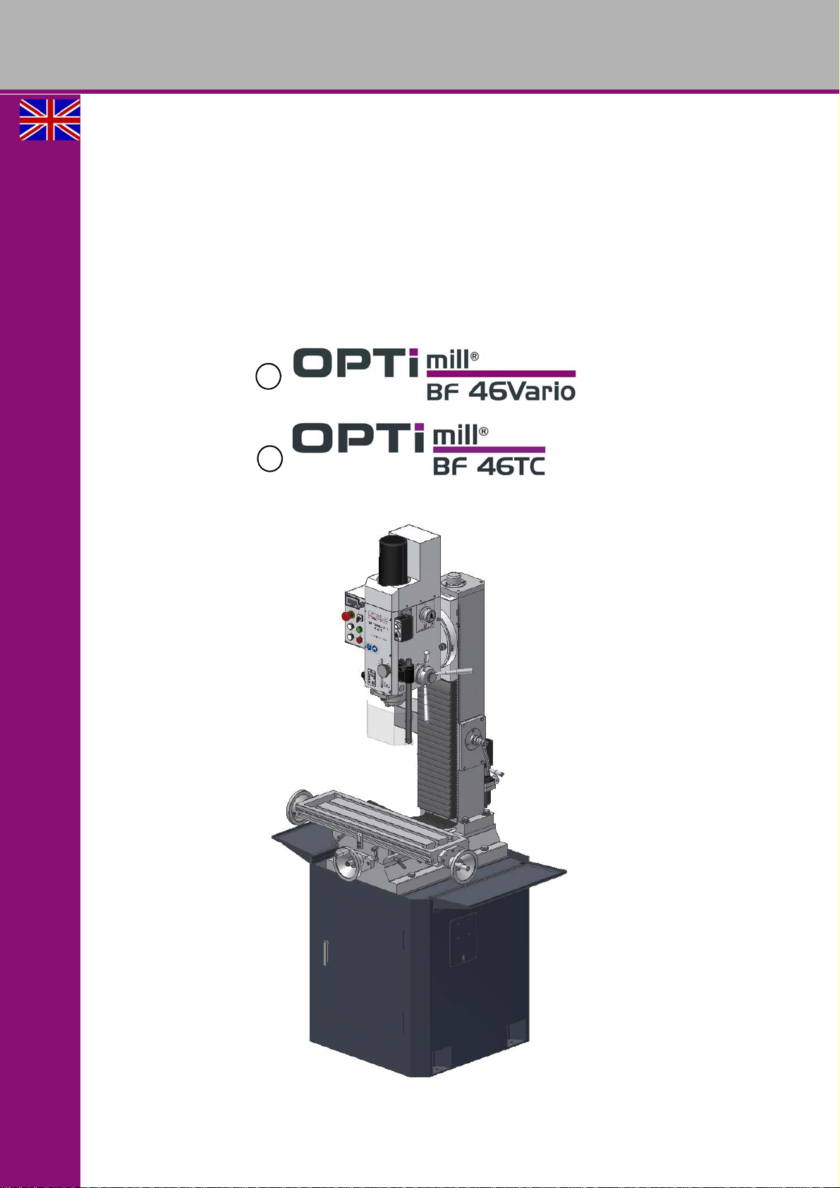
BF46 Vario | BF46TC GB
4Operation
4.1 Control and indicating elements BF46V.................................................................................................27
4.1.1 Control panel..........................................................................................................................................28
4.2 Switching on the drilling-milling machine................................................................................................29
4.3 Switching off the drilling-milling machine................................................................................................29
4.4 Inserting a tool on BF46V.......................................................................................................................30
4.4.1 Installation..............................................................................................................................................30
4.4.2 Unfitting..................................................................................................................................................30
4.5 Threading ...............................................................................................................................................31
4.6 Control and indicating elements BF46TC...............................................................................................32
4.6.1 Control panel BF46TC............................................................................................................................33
4.7 Switching on the drilling-milling machine................................................................................................34
4.8 Switching off the drilling-milling machine................................................................................................35
4.9 Traveling the drilling milling head (Z-axis) upward respectively downward............................................35
4.9.1 Traveling the drill-mill head upward respectively downward by actuating the crank handle ..................35
4.10 Threading ...............................................................................................................................................36
4.10.1 Traveling the drill-mill head upward respectively downward using the control panel.............................36
4.11 Inserting a tool on BF46TC ....................................................................................................................36
4.11.1 Installation..............................................................................................................................................36
4.11.2 Unfitting..................................................................................................................................................37
4.12 Safety.....................................................................................................................................................39
4.13 Use of collet chucks ...............................................................................................................................39
4.14 Clamping the workpieces .......................................................................................................................39
4.15 Changing the speed range.....................................................................................................................39
4.16 Manual spindle sleeve feed with the fine feed........................................................................................40
4.17 Digital display for spindle sleeve travel ..................................................................................................40
4.17.1 Malfunctions...........................................................................................................................................41
4.18 Manual spindle sleeve feed with the spindle sleeve lever......................................................................42
4.19 Swivelling the drill-mill head...................................................................................................................42
4.20 Selecting the speed................................................................................................................................42
4.20.1 Standard values for cutting speeds........................................................................................................43
4.20.2 Standard values for speeds with HSS – Eco – twist drilling...................................................................44
5 Maintenance
5.1 Safety.....................................................................................................................................................45
5.1.1 Preparation.............................................................................................................................................45
5.1.2 Restarting...............................................................................................................................................45
5.2 Inspection and maintenance ..................................................................................................................46
5.3 Repair.....................................................................................................................................................49
6 Ersatzteile - Spare parts
6.1 Fräskopf - Milling head 1 - 3...................................................................................................................50
6.2 Fräskopf- Milling head BF 46 TC Vario ..................................................................................................51
6.3 Fräskopf - Milling head 2 - 3..................................................................................................................52
6.4 Fräskopf - Milling head 3 - 3...................................................................................................................53
6.5 Fräskopf - Milling head BF46TC.............................................................................................................53
6.6 Säule - Column.......................................................................................................................................54
6.7 Säule - Column BF46TC ........................................................................................................................55
6.8 Kreuztisch - Cross table 1 - 2.................................................................................................................56
6.9 Kreuztisch - Cross table 2 - 2.................................................................................................................57
6.10 Schutzeinrichtung - Protection device....................................................................................................58
6.11 Maschinenunterbau (Optional) - Machine stand (option) .......................................................................59
6.12 Maschinenschilder - Machine labels ......................................................................................................60
6.12.1 Maschinenschilder - Machine labels ......................................................................................................60
6.12.2 Ersatzteileliste - Spare parts list.............................................................................................................61