opto engineering AOL0223B User manual

AO series
Adaptive lens for fast focusing
v 1.1

AO SERIES | INSTRUCTIONS MANUAL
2
Index
1. General information.............................................................................................................4
1.1 Installation, use and maintenance manual ..................................................................4
1.2Identicationdataoftheproduct..................................................................................4
1.3 Content of delivery ..........................................................................................................5
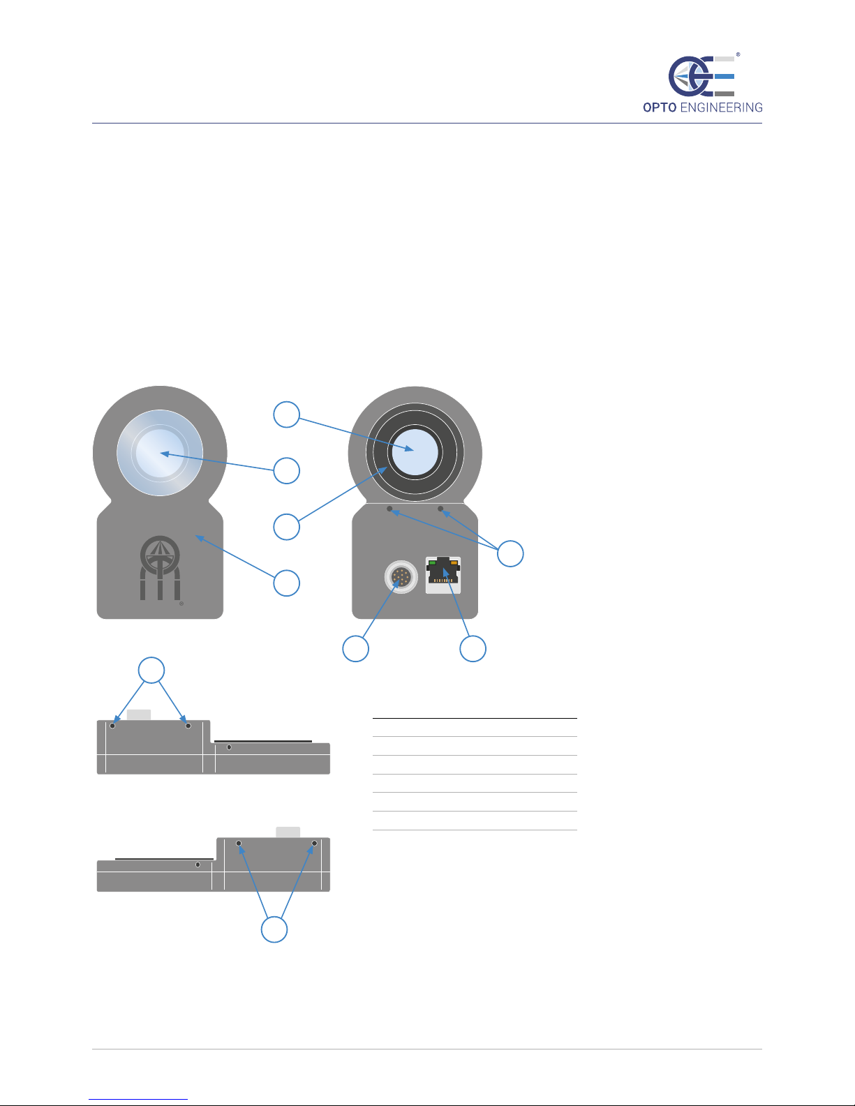
1.4Overviewoftheproduct .................................................................................................5
2. Characteristics and description..........................................................................................6
2.1 Working principle.............................................................................................................6
2.2Technicalspecications...................................................................................................7
2.3 Connections......................................................................................................................9
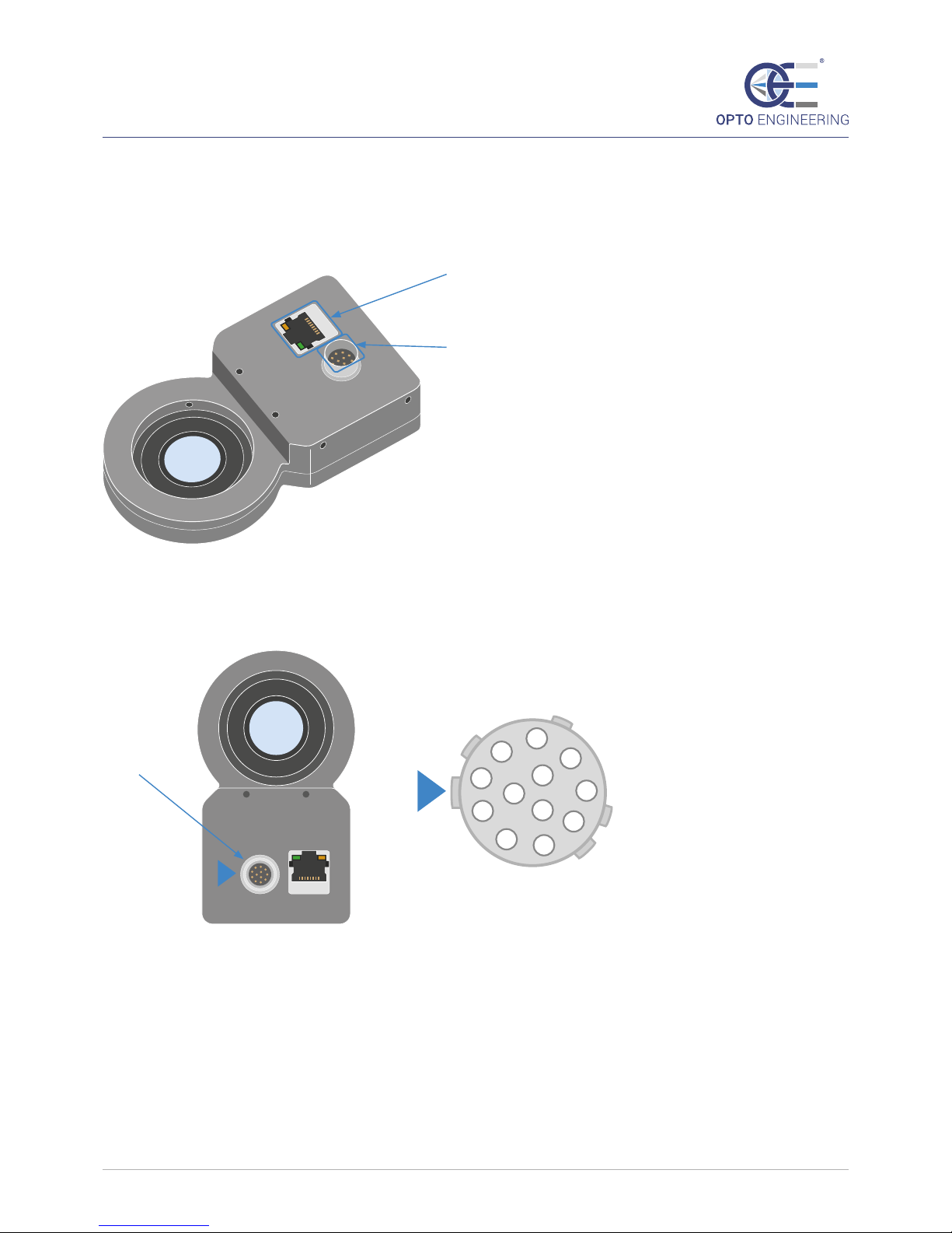
2.3.1 Layout of connectors ............................................................................................9
2.3.2 Power supply ...................................................................................................... 10
2.3.3Ethernet............................................................................................................... 10
2.3.4 RS232 ................................................................................................................... 11
2.3.5Synchronizationoutput ..................................................................................... 11
2.3.6 Analog control..................................................................................................... 13
2.3.7 Digital control...................................................................................................... 14
2.3.8 Wiring diagrams ................................................................................................. 15
3. Storage and use.................................................................................................................. 17
3.1 Storage conditions........................................................................................................ 17
3.1.1 Temperature ....................................................................................................... 17
3.1.2 Humidity.............................................................................................................. 17
3.1.3 Vibration and positioning.................................................................................. 17
3.2 Working conditions....................................................................................................... 17
3.2.1 Temperature ....................................................................................................... 17
3.2.2 Humidity.............................................................................................................. 18
3.2.3 Vibration and positioning.................................................................................. 18
3.3 Clamping and power supply........................................................................................ 18
3.3.1.Mechanicalxing............................................................................................... 18
3.3.2. Power supply ..................................................................................................... 18
4. How to use the product .................................................................................................... 19
4.1 Demo interface.............................................................................................................. 19
4.1.1 Software access .................................................................................................. 19
4.1.2 Lens control ........................................................................................................ 21
4.1.3 Automatic test loop............................................................................................ 21
4.1.4 IP settings ............................................................................................................ 22
4.1.5 Output trigger signal.......................................................................................... 22
4.1.6 Analog/Digital input signals .............................................................................. 23

AO SERIES | INSTRUCTIONS MANUAL
3
4.2 Dll controls..................................................................................................................... 24
4.2.1 Adaptive Lens DLL.............................................................................................. 24
4.2.1.1 Basic Data Structure ............................................................................. 24
4.2.1.2 Functions................................................................................................ 24
4.2.2 AutoFocus DLL.................................................................................................... 28
4.2.2.1 Basic Data Structure ............................................................................. 28
4.2.2.2 Functions................................................................................................ 28
4.3 TCP Communication ..................................................................................................... 30
4.4 Serial comunication protocol ...................................................................................... 31
4.4.1 Use ....................................................................................................................... 31
4.4.2 Functions ............................................................................................................. 32
4.4.3Examples ............................................................................................................. 34
4.5Ethernetrmwareupdate ........................................................................................... 35
5. Maintenance and cleaning ............................................................................................... 36
5.1 How to clean.................................................................................................................. 36
5.2Howtochangethemechanicaladapters .................................................................. 36
5.2.1 AOLM27X05AR, AOLM305X05AR, AOLM375X05AR and AOLCM.................. 37
5.2.2 AOLCF .................................................................................................................. 38
5.3Howtoreplacetheprotectivewindow ...................................................................... 40
5.4Extraordinarymaintenance......................................................................................... 42
5.5 Disposal.......................................................................................................................... 42
6. Safety notes......................................................................................................................... 42
6.1 General disclaimer....................................................................................................... 42
6.2 Forbidden use .............................................................................................................. 42
7. Product warranty ............................................................................................................... 44
7.1 Warranty ....................................................................................................................... 44
7.2 Applied directives ........................................................................................................ 44
8. Accessories.......................................................................................................................... 45
8.1 Adapter rings................................................................................................................ 45
8.2 Cables............................................................................................................................ 45

AO SERIES | INSTRUCTIONS MANUAL
4
1. General information
1.1 Installation, use and maintenance manual
Opto Engineering s.r.l.,withitsregisteredoceinstradacirconvallazionesud15,
46100Mantova(Mn)-Italy,hereinafterthemanufacturer,providesallthenecessary
informationinthisinstallation,useandmaintenancemanualinaclearandsimpleway
to install, use and service product AOL0223A and AOL0223B.
Therecipients of this manual areallthosewhohavetheknowledge,experienceand
capabilityofunderstandingthestandards,prescriptionsandsafetymeasuresindicated
inthismanual.
Suchpeoplewillbelateridentiedasqualied personnel whoareauthorizedto
transport,install,useandservicetheproductsdescribedinthismanual.
Thismaterialcanonlybeusedbythecustomerwhomthismanualhasbeendelivered
toinordertoinstall,useandservicetheproduct.
Themanufacturerwillretaintherighttomodifyorimprovethemanualand/orthe
productreferredtointhismanualwithoutanypriornotice.
Thefollowingtopographicconventionsarefollowedinthismanual:
1.2 Identication data of the product
ProductsAOL0223AandAOL0223Bareidentiedwithalabelplacedontheirtop.
Thislabelisusedtoidentifythepartnumber,theserialnumberandtheMACaddress
ofeachproduct.Thissetofdataisusedtoidentifyasingleproductdeliveredbythe
manufacturer.
NOTE: notes contain important information and are highlighted outside the text they refer to
WARNING: these guidelines outline
certain steps that can damage
the product itself if they are not
followed
DANGER: these guidelines outline
certain steps that can cause injury
or aect the health of operators
if they are not followed
REACH
COMPLIANT
RoHS
REACH
COMPLIANT
RoHS

AO SERIES | INSTRUCTIONS MANUAL
5
1.3 Content of delivery
Thecontentofthedeliveryconsistsof:
➝Adaptivefocusinglens,positiveornegativedependingonthepurchasedP/N
➝AdapterringtomounttheAOmoduleonalenswithM30.5x0.5lterthread
1.4 Overview of the product
Thefundamentalpartsoftheproductarelistedbelow.
1
2
3
6
4 5
Number Description
1Focusing lens
2Protective window
3Adapter ring
412-pin Hirose
5RJ45
6Protective cover
7Clampingholes
7
7
7
O
P
T
O
E
N
G
I
N
E
E
R
I
N
G
O
P
T
O
E
N
G
I
N
E
E
R
I
N
G
O
P
T
O
E
N
G
I
N
E
E
R
I
N
G

AO SERIES | INSTRUCTIONS MANUAL
6
2. Characteristics and description
2.1 Working principle
TheAOseriesisafocusingmodulewhichcanbemountedinfrontofaxedfocal
lengthlenstorapidlychangefocus.
TheAOseriesallowstheusertorefocusthelensfasterthanmovingthelens
mechanicallywithtraditionalmotorizedsolutions.
Thebuilt-indriverhasbeenspecicallydevelopedtoaccuratelycontrolthepiezoelectric
elements.
Ademouserinterfacewithbasiccontrolfunctionsisavailableviaawebbrowser
interface.Thelenscanalsobefullycontrolledwithadedicated.dlllibrary,
downloadablefromtheOptoEngineering®website.Thelibraryincludesanautofocus
algorithmandacalibrationtooltohelpusersintegratetheAOmoduleintotheir
product or application.
Therearetwoversionsoftheadaptivelens.VersionAhaspositiveopticalpowerand
versionBhasnegativeopticalpower.Thepositivelenscanchangethebestfocusplane
fromfartoclosewhilethefocusingpowermovesfromzerotothemaximumpower.
Thenegativelenscanchangethebestfocusplanefromclosetofarwhilethefocusing
powermovesfromzerotothemaximumpower.

AO SERIES | INSTRUCTIONS MANUAL
7
2.2 Technical specications
Thetechnicalspecicationsareindicatedbelow.
Part number AOL0223A
Optical specications
Power (min) (D) 0
Power(max) (D) 3.5
Clear aperture (mm) 23
Scan rate (Hz) 100
Transmittance (%) >90
Electrical specications
DC voltage (V) 24
Powerconsumptionmax (W) 5
Operating temperature 10 to 40
Storage temperature 0 to 50
Enviromental
Humidity 10-85% non condensing
IP rating
Installation Indoor use only
Communication
Connector 1RJ45, 12-pin Hirose
Interfaces 2Ethernet,RS232
I/O signal functions Analog control - Digital control - Ready
Mechanical specications
Mount M30.5x0.5
Length (mm) 116
Width (mm) 63
Height (mm) 27.7
Material Anodizedaluminum,scratchresistantpolycarbonate(LexanMargard®)
Clamping system 6xM3holes
Compatibility
Lenses ENMPseries,ENHRseries-EN2MPseries,EN5MPseries
Cameras mvBueFOX3-2 series,mvBlueCougar series
Cable CBUSB3001, CBETH003, CBGPIO001
1Standard industrial circular connector, for I/O and power connections.
2Custom protocol, see manual for more information.

AO SERIES | INSTRUCTIONS MANUAL
8
Part number AOL0223B
Optical specications
Power (min) (D) 3.5
Power(max) (D) 0
Clear aperture (mm) 23
Scan rate (Hz) 100
Transmittance (%) >90
Electrical specications
DC voltage (V) 24
Powerconsumptionmax (W) 5
Operating temperature 10 to 40
Storage temperature 0 to 50
Enviromental
Humidity 10-85% non condensing
IP rating
Installation Indoor use only
Communication
Connector 1RJ45, 12-pin Hirose
Interfaces 2Ethernet,RS232
I/O signal functions Analog control - Digital control - Ready
Mechanical specications
Mount M30.5x0.5
Length (mm) 116
Width (mm) 63
Height (mm) 27.7
Material Anodizedaluminum,scratchresistantpolycarbonate(LexanMargard®)
Clamping system 6xM3holes
Compatibility
Lenses ENMPseries,ENHRseries-EN2MPseries,EN5MPseries
Cameras mvBueFOX3-2 series,mvBlueCougar series
Cable CBUSB3001, CBETH003, CBGPIO001
1Standard industrial circular connector, for I/O and power connections.
2Custom protocol, see manual for more information.

AO SERIES | INSTRUCTIONS MANUAL
9
2.3 Connections
2.3.1 Layout of connectors
Figure 1: view of the AOL0223X connections.
Pinout for the 12-pin Hirose connector
Figure 2: Top view of the Hirose 12-pin connector for reference pin detection.
RJ45 Connector
Pin Reference
Hirose12-PINConnector
[P.N.:HR10G-10R-12PB(71)]
1
23
4
5
6
7
8
9
10
11
12
Connector top view

AO SERIES | INSTRUCTIONS MANUAL
10
Connector Pinout CBGPIO001 WIRE COLOR ** Signal
1 Blue GND(-)
2 Red 24V (+)
3 Pink NC
4 Grey A/D_IN_0
5 Yellow NC
6 Green DIG_OUT -
7 Brown COMMON(Dig_IN)
8White RS232_RX*
9 Black RS232_TX*
10 LightBlue DIG_OUT +
11 Orange A/D_IN_1
12 Violet NC
Shield (no color) PE
Table 1: Hirose 12-pin connector pinout (top view of male connector present on the AOL0223X).
*RS232_RXandRS232_TXrefertotheinternalelectronics.
Connectthe“UserRS232_TX”and“UserRS232_RX”topin8and9,respectively.
**CBGPIO001isthepartnumberoftheHirose12-pinconnectorcable(withyingleadstermination).
Thegureaboveistherepresentationofthepinoutofthemaleconnectorpresent
ontheAOL0223Xelectronicboard(topview).Thereferenceforpin1canbeseen
in Figure 2.
2.3.2 Power supply
Powersupplyisdirectlyfedthroughpin1andpin2oftheHirose12-pinconnector.
Powersupplyspecicationsarelistedinthefollowingtable.
Specication Value
Voltage[V] 24
Power[W] 5
2.3.3 Ethernet
EthernetcommunicationisusedfordatatransmissionbetweenthePCandAOL0223X,
usingTCP/IPprotocol.ConnectAOL0223XdirectlytothePCusingastandardEthernet
cable.
ThedefaultparametersforstartingthecommunicationwiththeAOL0223Xarelistedin
thefollowingtable:
Parameter Default Value
IP Address (Static) 192.168.1.200
Subnet Mask 255.255.255.0

AO SERIES | INSTRUCTIONS MANUAL
11
ThedefaultcongurationusesaSTATICandPREDEFINEDIPAddress,butit’spossibleto
changethiskindofconguration.Inparticular,anewstaticIPAddresscanbesetbythe
usereitherviaEthernetortheserialRS232(pleaserefertoParagraph13and15forIP
Addressreconguration).
2.3.4 RS232
TheserialcommunicationisimplementedinsidetheHirose12-pinconnectorbyusing3
pins,listedinthefollowingtable:
Function Pin on Hirose Connector Cable color of CBGPIO001 Connect to
Ground 7 Brown GND
AOL_RS232_RX 8 White User_RS232_TX
AOL_RS232_TX 9 Black User_RS232_RX
TheelectricalspecicationsoftheRS232signalsarelistedinthefollowingtables:
Specication min max Unit
DataIN(User_TX) -25 25 V
Data OUT (User_RX) -13.2 13.2 V
Specication Value
Baud Rate 115200
Numberofdatabits 8
Stop bit 1
Parity bit no
Terminationchar /r
Pleasereferto“SerialCommunicationProtocol”(Paragraph15)toapplyRS232tothe
lens.
2.3.5 Synchronization output
Oneofthe12pinsoftheHiroseconnectorisusedasanoptoisolatedoutputfor
synchronizationofexternalsystems.Theelectricalschematicoftheoptoisolatedoutput
signalisshowninFigure4:
Figure 4: Schematic of the optoisolated output.
Tocompletethewiringcongurationsoftheoptoisolatedoutputcorrectlyoneofthe
1
AOL0223X Output Signal
4
2 3

AO SERIES | INSTRUCTIONS MANUAL
12
followingschemescanbechosen(Figure5):
Figure 5: Two possible wiring congurations for the optoisolated output.
The rst two congurations refers to non opto-isolated digital inputs, the other two to opto-isolated digital inputs.
Therstcongurationusesapull-upresistortoobtainan“active-low”outputsignal;in
thesecondcongurationthepull-downresistorallowsthegenerationofanon-inverting
output signal.
Theelectricalspecicationoftheoptoisolatorarelistedinthefollowingtable:
Specication Test condition Value Unit
Collector-emitter voltage (VCEO) 70(max) V
Emitter-collector voltage (VCEO) 7(max) V
Collector current (IC) 50 mA
Collector peak current (ICP) tp/T = 0.5, tp≤10ms 100 mA
Collector dark current (IC,DARK) VCE = 20 V, IF= 0 A 100 nA
Collector emitter saturation voltage IF= 10 mA, IC= 1 mA 0.3 V
+V
+V
0
GND GND
Inverting
OPTO-ISOLATED OUTPUT
LOGIC DIGITAL INPUT
+V
+V
0
GND
GND
Non-Inverting
OPTO-ISOLATED OUTPUT
LOGIC DIGITAL INPUT
+V
GND
OPTO-ISOLATED OUTPUT
DEVICE OPTO-ISOLATED INPUT
+V
0
Inverting
+V
GND
OPTO-ISOLATED OUTPUT
DEVICE OPTO-ISOLATED INPUT
+V
0
Non-Inverting

AO SERIES | INSTRUCTIONS MANUAL
13
2.3.6 Analog control
AOL0223Xincludestwogeneralpurposeinputswhichcanbeconguredeitheras
analogordigital.TheseareNOToptoisolatedports.TheelectricalschemeoftheseGPI
isshowninFigure6:
Figure 6: Electrical scheme of the two general purpose input ports.
Theinputvoltagedividerisdimensionedtoworkwitha0-24Vdynamicrangeforthe
input signal.
ThetwoSchottkydiodesandtheadditional100Ohmresistorarenecessarytoavoid
possible transient overvoltages (over 3.3V) or undervoltages (below 0V). However, since
no optoisolation is present, please be careful to connect well-controlled signals.
Example
Figure 7: application example.
GND
INPUT1
GND
20kohm 100
3.16kohm D2
D1
3.3V
GND
INPUT2
GND
20kohm 100
3.16kohm D2
D1
3.3V
Electrical Specications for A/D input ports
Min Max Unit
Input Voltage 0 24 V
Input Dynamic Range
(DiscretizationLevels) 100
(Voltagediscretization) 240 mV
GND
INPUT1
GND
20kohm 100
3.16kohm D2
D1
3.3V
Analog signal
(0 ≤ VIN ≤ 24V)
AOL0223X
Electronics
DIG_OUT
SYNC_OUT
AOL0223X
Output Signal
(0 ≤ VLENS ≤ 300V)
CAMERA

AO SERIES | INSTRUCTIONS MANUAL
14
Onepossibleapplicationcanbethefollowing(Figure7):ananalogsignalrangingfrom
0to24Vcanbefedtothe“A/D_IN_0”pin,inadiscreterampsignal(Figure8),asan
example.
Foreachinputvoltagelevel,aproportionaloutputsignalcanbegenerated:once
theoutputvoltagereachesasteady-statevalue,the“DIG_OUT”pincanbeusedfor
triggeringtheimageacquisition.Aftertheendoftheacquisition,thecameracan
communicatewiththeanalogsignalgenerator,therebymovingontothenextvoltage
levelofthestaircasesignal.
Afterhavingcoveredtheentireinputdynamic(0–24V),asetofdierentimageshas
beenacquiredbythecameraandisavailabletobeprocessedinordertondthebest
focus.
Consideringthe12-bitresolutionADC,betterprecisioncanbeachievedbyincreasing
thenumberofinputvoltagelevels.
Figure 8: Discrete ramp signal.
2.3.7 Digital control
Pin4(A/D_IN_0)andPin11(A/D_IN_1)canalsobeusedasadigitalinput(0:LOW–1:HIGH).
Inthiscase,aninputsignalwhosevaluerangesbetween0Vand8VisconsideredaLOW
leveldigitalsignal(logic0),whereasaninputsignalwhosevaluerangesbetween16V
and 24V is considered a HIGH level digital signal (logic 1).
Example
Figure 9: AOL0223X Digital control.
VINANALOG[V]
t[ms]
GND
INPUT1
GND
20kohm 100
3.16kohm D2
D1
3.3V
GND
INPUT2
GND
20kohm 100
3.16kohm D2
D1
3.3V
Output Signal
(0 ≤ VLENS ≤ 300V)
DIG_OUT
MOVE/STOP
DIRECTION
AOL0223X
AOL0223X
Electronics
CAMERA

AO SERIES | INSTRUCTIONS MANUAL
15
Inthisexample,thetwoA/Dinputportsaredirectlylinkedtotwodierentcamera
outputs.
Therstsignalis“MOVE/STOP”,whichisLOWwhenthebestfocuspositionhasalready
beenset,andHIGHwhenanewfocuspositionmustbereached.
Theothersignalis“DIRECTION”:theAOL0223Xonlytakescareofthissignalif“MOVE/
STOP”ishigh.
IfDIRECTIONisLOW,theoutputvoltageappliedtothepiezoelectricactuatordecreases,
andwhenDIRECTIONisHIGH,theoutputvoltageincreases.
Asuitabletriggering,controlandsynchronizationsystemisrequiredbetween
AOL0223Xandthecameratoimplementthiskindofcontrolcorrectly.
2.3.8 Wiring diagrams
Thisfunctioncodeisusedtowriteablockofcontiguousregistersinthecontroller
registerle.Themasterspeciesthestartingregisteraddress,thenumberofregisters
andtheactualdatatobewritten.Registersareaddressedstartingatzero.Theregister
dataintherequestmessagearepackedastwobytesperregister.Foreachregister,the
rstbytecontainsthehighorderbitsandthesecondcontainstheloworderbits.The
normalresponsereturnsthefunctioncode,startingaddress,andquantityofregisters
written.
Example 1: AOL0223XisconnectedtothepowersupplyandtothePC.
TheconnectiontothePCviatheethernetcableisnecessaryfortheelectroniccontrolof
theAdaptiveLens.
ThedefaultsettingsfortheEthernetconnectionareillustratedinParagraph11.3.
PC
EthernetPort
POWER SUPPLY
24 V
GND

AO SERIES | INSTRUCTIONS MANUAL
16
Example 2: AOL0223Xisconnectedtothepowersupplyandtothecamera.
CommandsaresentthroughRS232signals.
TheoutputsignaloftheAOL0223Xisusedtoletthecameraknowthatthesystemis
readyfortheacquisition.RememberthatthissignalisOPTOISOLATED,therefore,for
example,the“DIG_OUT+”canbeconnectedtothecamerapowersupply(ordirectlyto
the24Vifthecamerais24Vtolerant)and“DIG_OUT-”totheTRIGGERINofthecamera.
Example 3: AOL0223Xisconnectedtothepowersupply,tothecameraandtothePC.
ThecommunicationisbasedonTCP/IPprotocolviaEthernettothePC.
Inthiscase,digitalcontrolisimplementedtondthebestfocus:MOVE/STOPand
DIRECTIONsignals(describedinParagraph11.7)areconnecteddirectlytotheinput
pinsoftheAOL0223X.
Theoutputsignal(OPTOISOLATED)isusedtotriggertheimageacquisition.Pleaserefer
tothepreviousexampleforthecongurationoftheoptoisolatedoutputsignal.
POWER SUPPLY
24 V
GND
CAMERA
TriggerIN
Trigger OUT
RS232 RX
RS232 TX
RS232 COM
CAMERA
CAMERA POWER SUPPLY
PC
EthernetPort
CAMERA
TriggerIN
MOVE/STOP
DIRECTION
POWER SUPPLY
24 V
GND
CAMERA
CAMERA POWER SUPPLY

AO SERIES | INSTRUCTIONS MANUAL
17
PC
EthernetPort
CAMERA
TriggerIN
MOVE/STOP
POWER SUPPLY
24 V
GND
CAMERA
CAMERA POWER SUPPLY
Example 4: AOL0223Xisconnectedtothepowersupply,tothecameraandtothePC.
ThecommunicationisbasedonTCP/IPprotocolthroughEthernettothePC.
Inthiscaseananalogcontrol(describedinParagraph11.6)isimplementedtondthe
bestfocus:theanalogsignalcomingfromthecameraorfromanexternalsourceisfed
totheinputoftheAOL0223X.
Theoutputsignal(OPTOISOLATED)isusedtotriggertheimageacquisition.Pleaserefer
tothepreviousexampleforconguringtheoptoisolatedoutputsignal.
3. Storage and use
3.1 Storage conditions
3.1.1 Temperature
Storageenvironmentbetween0°and50°C.Avoidthermalshockbynotexposingthe
producttosuddenchangesintemperature.
3.1.2 Humidity
Storetheproductinadryplace:storageenvironmentwithrelativehumidity(RH)less
than85%(nocondensation).
3.1.3 Vibration and positioning
Alwayshandletheproductwithcare.Storetheproductinasafeplaceinsideitsoriginal
packing material.
3.2 Working conditions
3.2.1 Temperature
Operating environment between 5° and 45° C.
Extremetemperaturesaectthefunctionalityoftheproduct,especiallytheelectronic
components.
Avoidthermalshockbynotexposingtheproducttosuddenchangesintemperature.
Sincetheproductincludeselectroniccomponents,itmaygenerateheatwhen
functioning.Alwaysallowenoughroomtodissipatetheappropriateamountofheat
(ifnecessaryoperating,byforcingtheair).

AO SERIES | INSTRUCTIONS MANUAL
18
3.2.2 Humidity
Operatingenvironmentwithrelativehumidity(RH)lessthan85%(nocondensation)..
3.2.3 Vibration and positioning
Theproductisahighprecisioninstrument.Avoidmechanicalshockandexposureto
vibrations:lensesaremadeoffragilematerialswhichcanfracture.
Alwayshandletheproductwithcareanduseappropriateclampingmechanicsto
position it.
Neveruseopticalpartsoftheproductasmeansofmechanicalsupport.
Donotplacetheproductonanunstablestand,tripod,baseortableandonuneven
oors.Ifthelensweretofall,itcouldcausepersonalinjuryandmaybedamaged.
Ifthelensisplacedvertically,withthemechanicalaxisnearlyperpendicular(+/-30°)to
theoor,operatorsshouldneverplacetheirhandsunderthelens,toavoidinjuriesdue
tothemechanicaloropticalcomponentspossiblyfalling.
ThedevicehasanIPratingof20andshouldbeinstalledinawayformoistureanddirt
not to enter it.
Anenclosuremayalsoberequiredforotherpartsofthesystem,suchaspower
supplies.Suchanenclosurewouldprovidebothmechanicalandenvironmental
protection in industrial applications.
3.3 Clamping and power supply
3.3.1 Mechanical xing
Aftertheproducthasbeensetinplace,accordingtotheeldofview,itcanbesecured
byusingatleast2ofthe6M3clampingholes.
Ifyouareusingtheproductwithaxedfocallensandacamera,itisalways
recommendedtoholdtheentiresysteminplacebyusingtheM3clampingholes.Avoid
holdingtheentiresysteminplacebythecameraorbythexedfocallens.Thelter
threadadapterisnotthemechanicalholderofthesystem.
3.3.2 Power supply
ThesystemcanbeconnectedtothepowersupplyusingtheCBGPIO001cablelistedin
theaccessoriessection.
Theelectricpowersupplyshouldnothavevoltageoscillationhigherthan±5%.
Alwayscheckthatthepowersupplycableisingoodcondition.Avoidstressingor
bendingastheconductorscouldbedamaged.
Thepowersupplymusthaveanappropriateearthconnection.
WARNING: Do not hold the device in place by using the adapter lter ring
WARNING: Always check that the power supply voltage, maximum output power
and operating frequency are correct for the product

AO SERIES | INSTRUCTIONS MANUAL
19
4. How to use the product
4.1 Demo interface
4.1.1 Software access
TheAOL0223XcanbecontrolledeitherviaEthernetorRS232.
ThisparagraphdescribestheEthernetcontrolmethod,highlightingtheDemointerface
functions.
IftheAOL0223Xisswitchedonforthersttime,apreliminarycongurationisrequired.
Infact,thedefaultIPAddressoftheAOL0223X(writteninanon-volatilememory)is
192.168.1.200:thePCnetworkpropertiesmustbechangedtoaccesstheweb-based
application.
Inparticular,thefollowingparametershavetobesetintheNetworkControlPanelof
thePC(TCP/IPv4):
➝IPAddress:192.168.1.X(Xcanbeavaluethatisnotusedbyotherperipherals-
AOL0223Xincluded–rangingfrom1to255.Value200isn’tavalidvaluesinceit
isusedfortheAOL0223);
➝Subnetmask:255.255.255.0;
➝DefaultGateway:notdened.
TheIPAddresscanbechangedatanymomentusingboththeDEMOprogramandthe
serialcommunicationprotocol(seeParagraph13.5and15.2,respectively).
Pleasebeawarethatifthenewuser-denedIPaddressisaccidentallylostorforgotten,
thereisnopossibilitytoretrieveitusingtheDEMOinterface.However,theIPAddress
valuecanberetrievedusingRS232commands(seeParagraph15.2).
Afterthepreliminarynetworkconguration,theweb-basedDEMOinterfacecanbe
easilyaccessedbyenteringtheIPaddress192.168.1.200inthebrowser(orthenewIP
address,ifchanged).
MicrosoftEdge,GoogleChromeandMozillaFirefoxsupporttheDEMOapplication.
Otherbrowsershavenotbeentested.

AO SERIES | INSTRUCTIONS MANUAL
20
OncetheIPaddressisconnectedto,thefollowingwebpagewillbedisplayed:
This manual suits for next models
2
Table of contents
Other opto engineering Lens manuals
Popular Lens manuals by other brands

Barco
Barco TLD HB (0.8:1) installation manual

Pentair
Pentair Fiberworks Wide Angle Lens installation instructions

Irix
Irix 15 mm f/2.4 Extended user manual

Intova
Intova IWAL - UPC 814002010369 instruction manual

Sigma
Sigma 120-130mm F2.8 DG OS HSM instructions

Mitsubishi Electric
Mitsubishi Electric OL-XD8000EZ Mounting manual