OPTOGAMA MEX User manual

!
Alignment v1.1
MEX
Motorised laser beam expander
Alignment guide
KEY for DISCOVERIES

Table of contents"
Table of contents# "....................................................................................................................................2
1. Safety requirements# "...........................................................................................................................3
2. Alignment with 4 axis manual stage - MSTAGE / MSTAGE-W!..............................................................................................4
2.1.Mounting the expander!.................................................................................................................................................4
2.2.Positioning the stage!....................................................................................................................................................4
2.3.Pre-aligning the expander!.............................................................................................................................................5
2.4.Final alignment!..............................................................................................................................................................6
2.4.1.Placing a Target after beam expander!........................................................................................................................6
2.4.2.Checking the reflection!..............................................................................................................................................6
2

1. Safety requirements"
•All safety instructions must be followed.
•This manual should be read carefully before first
intended use.
•All rules and regulations concerning safe operation of
lasers must be known and applied while installing and
operating motorised beam expander.
•Even when with safety glasses avoid eye contact with
direct or scattered laser light while assembling, installing
and operating the device.
•The device should never be exposed to dirt, dust or
moisture.
•Before any operation make sure the device is installed
correctly and well adjusted.
•Protective measures should be considered if necessary.
•Electrical safety requirements must be complied while
operating this device.
CAUTION! High laser output power may damage or destroy
optical elements.
CAUTION! Make sure laser beam is not converging after
passing through the beam expander - it may damage other
optical elements along the optical axis.
CAUTION! Device is meant to be used with collimated
beam. Users take full responsibility when using the expander
with highly converging beam.
3

2. Alignment with 4 axis manual
stage - MSTAGE / MSTAGE-W "
MSTAGE manual stage is suitable for MEX13, MEX18
and MEX18-ACH motorised beam expanders.
MSTAGE-W wide manual stage is suitable for MEX13HP,
2.1.Mounting the expander"
1. Fix the motorised beam expander with M4x0.7
8-10mm long screws from the bottom side of the
manual stage:
2. When the expander is properly fixed, place the
manual stage (with fixed expander) on the bottom
side and fix it with Metric M6x1.0 or Imperial 1/4”-20
screws. It can be fixed on both Metric and Imperial
optical breadboards and tables:
2.2. Positioning the stage"
MSTAGE has 4xM6x0.25 microscrews for adjusting
platform’s pitch, yaw, Y and Z axis. Two microscrews control
platform’s pitch and Z axis, while another two control yaw
and Y axis. All of them can be adjusted with 2 mm HEX
screwdriver.
1. Make sure the Microscrew’s lock screws are loosen
before any adjustment.
NOTE: It is not necessary to unlock all microscrews if only
one axis is going to be adjusted.
CAUTION! Do not adjust the stage with adjustment
microscrews while the they are locked.
Z
Y
Pitch
Yaw
4

2.3. Pre-aligning the expander"
1. Make sure the expander is aligned so the laser beam
incidents in the centre of the beam expanders input:
1. Good alignment:
2. Bad alignment:
NOTE: the beam should remain in the centre in all
magnification range!
2. Make sure the output beam exits in the centre of the
lens as well:
1. Good alignment:
2. Bad alignment:
5

2.4. Final alignment "
2.4.1. Placing a Target after beam
expander"
When the beam expander is pre-adjusted, you can use a
target (or similar item) to check if any more precise
adjustment is necessary.
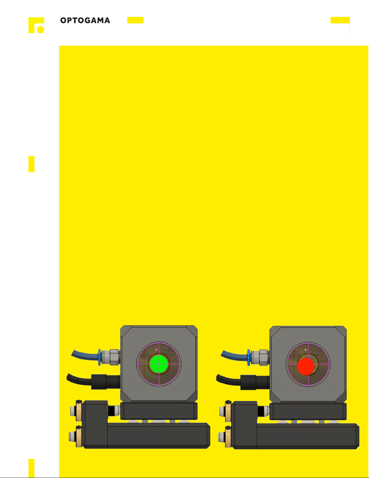
If the target is in far field (couple of meters) you can see
some huge beam shift before precise alignment:
Fig. Laser beam on target which is placed in around 3,5
meters distance from beam expander.
The object is to align the expander so the laser beam remain
at the same spot in the centre of the target. The easiest way
to do that is to use the BDS software and try to adjust the
expander while changing the magnification range from MIN
to MAX.
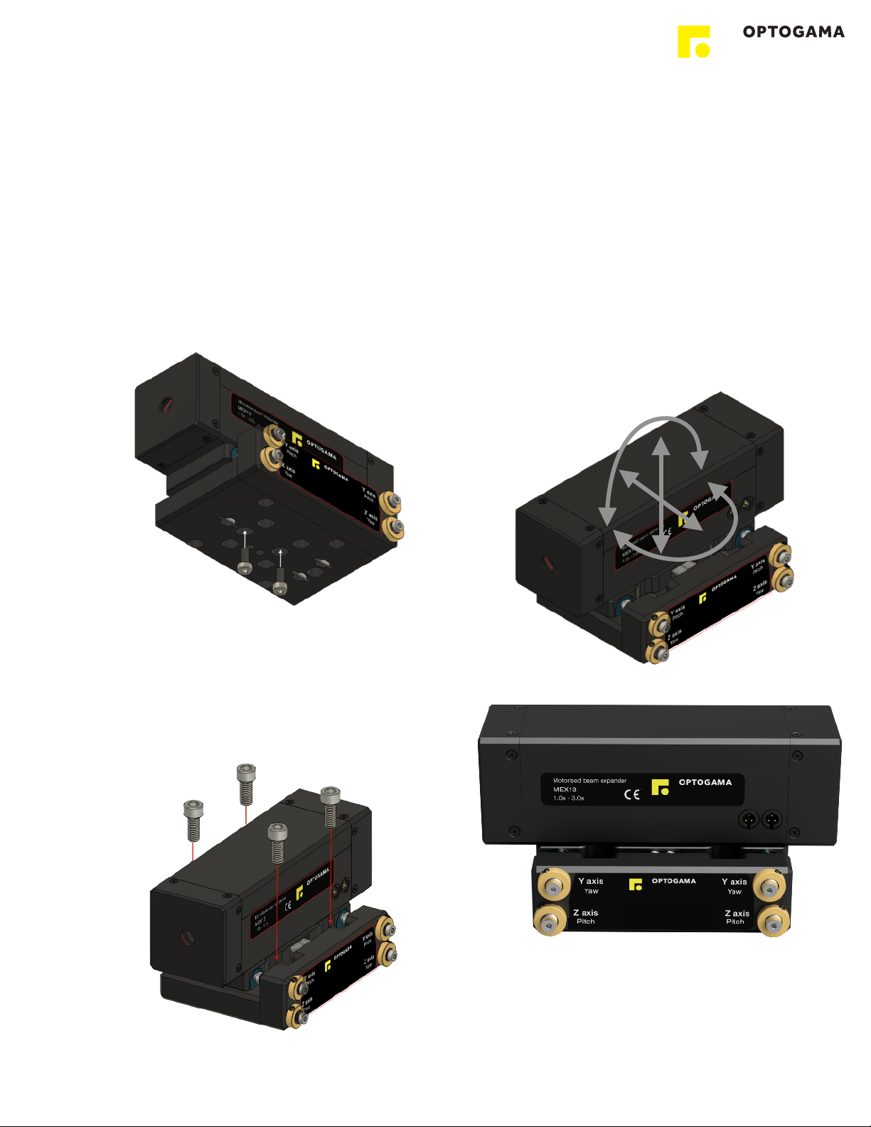
If the laser beam at MIN magnification (in this example 1X) is
in the centre of the target, you should adjust the expander’s
tilt (adjust pitch on MSTAGE) when at MAX magnification
and try to move the output beam to the centre of the target
(to match the 1X MAG position).
NOTE: MIN magnification configuration is less sensitive to
expander’s Tilt adjustment. It practically does not have any
impact to the output, so the Tilt adjustment should be made
while at MAX magnification configuration.
2.4.2. Checking the reflection"
One of the best ways to check If expander is tilted and
positioned properly is to check the reflections before the
beam expander (laser beam is reflected from expander’s
lenses).
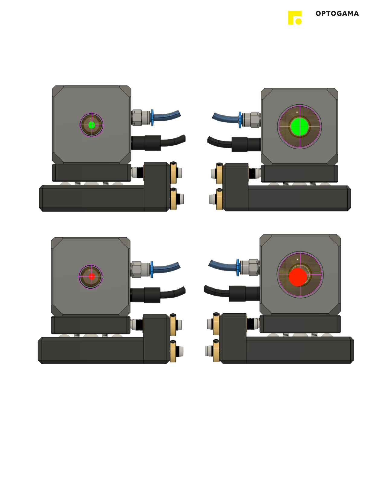
NOTE: In this image the reflected light is intense, because of
the coating of the lenses. Typically the reflected beam
intensity will be very low because of the AR/AR coatings.
The green circle shows the reflected beam from planar
surface of the lens. From this image we can indicate that the
expander needs to be tilted. To do that tilt the manual 4 axis
stage using micro-screw for pitch (Z axis, pitch).
The purple circle shows reflection from all lenses in the
beam expander. This image indicates that the position of the
expander is also not in the centre of optical axis. To achieve
that X and Y stage positions should be adjusted.
The view after finishing the adjustment should be similar to
this:
!
6
Table of contents
Other OPTOGAMA Extender manuals