Abbott i-STAT Service manual

Abbott Point of Care Inc. •Abbott Park, IL 60064 •USA
Art: 726025-01A Rev. Date 24-NOV-14
Procedure for Using the i-STAT®1 Wireless Analyzer
VERVIEW
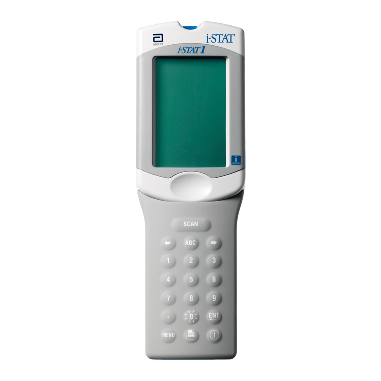
In response to customer requests for expanded wireless transmission capabilities for i-STAT data, Abbott Point of Care
has developed a new i-STAT 1 Wireless Analyzer (handheld) that can communicate to the Data anager via your
existing Local Area Network (LAN) wireless infrastructure (with certain restrictions). This Technical Bulletin describes
the procedures for:
•Testing i-STAT cartridges using the i-STAT 1 Wireless Analyzer
•Customizing the handheld to enable the Wireless functionality
•Transmitting data wirelessly to the Data anager
•Using the Wireless Utility enu to:
– View the Wireless Settings and
– Test the Wireless Connections
For i-STAT 1 Wireless Specifications, see the Technical Bulletin “i-STAT®1 Wireless Analyzer Specifications”
(Art: 728644).
For instructions on configuring an i-STAT 1 Wireless Analyzer, see the Technical Bulletin “Configuring Wireless
Settings in an i-STAT®1 Wireless Analyzer” (Art: 726066).
Note: Users must follow site-specific guidelines for operating wireless devices when using the i-STAT 1
Wireless Analyzer.
If you have any questions regarding the information in this Technical Bulletin, please contact your Support Services
provider.
i-STAT®
TECHNICAL BULLETIN

Art: 726025-01A2
TABLE F CNTENTS
TESTING i-STAT CARTRIDGES USING THE i-STAT 1 WIRELESS ANALYZER 2
CUST MIZING THE i-STAT 1 WIRELESS ANALYZER T ENABLE WIRELESS FUNCTINALITY2
A. Customizing the Handheld to Enable the Wireless Functionality Using the Handheld Keypad 3
B. Customizing the Handheld to Enable Wireless Functionality Using CDS Version 53
C. Customizing the Handheld to Enable Wireless Functionality Using i-STAT/DE5
C NFIGURING AN i-STAT 1 WIRELESS ANALYZER 6
TRANSMITTING RESULTS T THE DATA MANAGEMENT SYSTEM 6
A. Transmitting Data Wirelessly following a Test Cycle using the Test Options enu7
B. Transmitting Data Wirelessly Using the Transmit Data enu8
C. Transmitting Results Using the Downloader or Downloader/Recharger 9
THE WIRELESS UTILITY MENU 10
ERR R C DE MESSAGES 12
TESTING i-STAT CARTRIDGES USING THE i-STAT 1 WIRELESS ANALYZER
• The i-STAT 1 Wireless Analyzer has the capability to run all current i-STAT cartridges.
• The procedure for testing i-STAT cartridges using the i-STAT 1 Wireless Analyzer is identical to that used by the
i-STAT 1 Analyzer ( odel 300). Please refer to the i-STAT 1 System anual for full details on cartridge testing.
• Items needed for the method of powering the handheld are the same as for the i-STAT 1 Analyzer: two 9-volt
lithium batteries or a pair of rechargeable batteries purchased only from Abbott Point of Care. However, the
user should expect an approximate 30% reduction in the number of cartridges run per battery charge due to
the use of wireless downloads. Note: the 30% reduction is an approximation based upon a use model of
transmitting results wirelessly following each cartridge run.
CUST MIZING THE
i
-STAT 1 WIRELESS ANALYZER T ENABLE WIRELESS FUNCTI NALITY
Before configuring the handheld to perform wireless transmissions, the handheld must be customized to enable the
Wireless functionality.
The procedure to customize the handheld varies, depending upon whether or not the customization is being done
directly using the handheld’s keypad, or whether it is being done through the Customization Workspace in Central
Data Station (CDS) Version 5 or i-STAT/DE.
• Users who do not have CDS Version 5 or i-STAT/DE ➔Proceed to Section A.
• Users who have CDS Version 5 ➔Proceed to Section B.
• Users who have i-STAT/DE ➔Proceed to Section C.
Rev. Date 24-NOV-14

A. Customizing the Handheld to Enable the Wireless Functionality Using the Handheld Keypad
1. Press to turn on the handheld.
2. Press
to change screen to Administration Menu.
3. Press (Customization).
4. Press (Change).
5. Enter password and press , or just press
if no password is required.
6. Press (Analyzer).
7. Press twice.
8. Press (Wireless).
9. Press to change setting to Enabled.
10. The “Wireless” listing should now appear as Enabled.
11. Press to turn handheld off and save the settings.
(If setting
is not shown as Enabled, return to Step 9).
B. Customizing the Handheld to Enable Wireless Functionality Using CDS Version 5
1. Click on Main ➔pen Administration Function ➔Customization.
2. Type in your password and click OK. The default password is the word istat.
Note: Abbott Point of Care Inc. recommends changing the default password.
MENU
4
1
➔
1
ENT
3
ENT
3
15:26 18JAN10
Administration Menu
1 - Analyzer Status
2 - Data eview
3 - Quality Tests
4 - Customization
5 - Set Clock
6 - Transmit Data
7 - Utility
Customization
Default0
1 – View
2 – Change
2
2
Art: 726025-01ARev. Date 24-NOV-14 3
Main System Tools Window Help
Instrument/Location
Operator
Database Maintenance
Inventory
Customization
User Administration
Open Monitor
Open Administration Function
Open Data Viewer
Open Report
Close
Exit Alt+X
X
X
X
X
Password System Tools Window
X
A password is needed to access this workspace.
Password:
OK Cancel
Change
Customization
Default0
1 – Analyzer
2 – ID Entry
3 – Patient Tests
4 – QC Tests
5 – esults
6 – Password
7 – estore Factory
Settings
Analyzer
Customization
1 Wireless
Disabled
Change
Customization
Wireless
1 – Disabled
2 – Enabled

3. ake sure the Enable Customization box is checked.
Also, make certain that the Enable Updates box is checked for the particular location to which this i-STAT 1
Wireless Handheld is assigned.
4.
If the location to which this Handheld is assigned has a checkmark under the Use Default Profile column,
double click on the alphanumeric code under Preferences in the Default Customization Profile column.
Otherwise, double click on the alphanumeric code under Preferences for the specific location to which this
Handheld is assigned.
5.
Once the Preferences screen opens, click on the Instrument tab. Click the box to Enable wireless communication.
6. Click K and answer YES to the question about changing the preferences.
Enable Customization
¥
Location-based customization profiles:
A_10.10.90.17
A_10.10.90.24
A_10.10.90.31
A_10.10.90.32
X
Location Enable Use Update i-STAT Philips Preferences STATNotes
Updates Default CLEW Analyzer BAM
Profile
CLEW
CLEW
A18
A18
A18
A18
DEFAULT0 CHART0
DEFAULT0 CHART0
DEFAULT0 CHART0
DEFAULT0 CHART0
¥
¥
¥
¥
¥
¥
¥
¥
¥
¥¥ ¥
Preference Change Tools Window
X
You are changing the Preferences. Proceed?
Cancel
NoYes
U
!
➔
Art: 726025-01A4 Rev. Date 24-NOV-14

7.
Download the handheld to the CDS from a downloader in the location to which this handheld is assigned. This action
should upload the chosen customization features into the handheld. Repeat step 7 for all handhelds from this same
location to be customized. To customize handhelds from other locations for the same features, return to step 1.
C. Customizing the Handheld to Enable Wireless Functionality Using i-STAT/DE
1. Access the Customization Workspace
• RALS-Plus Users:
– For the RALS-Plus application, choose i-STAT from the drop-down menu.
– Click on Device Customization.
• PrecisionWeb Users:
– Double click on the desktop shortcut or Internet Explorer Favorites for i-STAT Customization.
2. ake sure the Enable Customization box has a check mark in it.
Also, make certain that the Enable Updates box is checked for the particular
location to which this i-STAT 1 Handheld is assigned.
3.
I
f the location to which this handheld is assigned has a checkmark under Uses Default, double click on the
alphanumeric code under Preferences in the Default Customization Profile column. Otherwise,
double click
on the alphanumeric code under Preferences for the specific location to which this Handheld is assigned.
4.
Once the Preferences screen opens, click on the Instruments tab. Check the box to Enable wireless communications.
Enable Customization
¥
ER
Lab
Location Enabled
¥
¥
➔
Art: 726025-01A 5Rev. Date 24-NOV-14

5. Click K and answer YES to the question about changing the preferences.
6. Download the handheld to the Data Manager from a downloader in the location to which the handheld is
assigned. This action should upload the chosen customization feature into the handheld. To customize additional
handhelds from this same location, repeat step 6. To customize handhelds from other locations for the same
features, return to step 1.
C NFIGURING AN
i
-STAT 1 WIRELESS ANALYZER
After customizing the handheld to enable the wireless functionality, the handheld must be configured to connect to
the facility’s WLAN. For instructions on configuring an i-STAT 1 Wireless Analyzer, see the Technical Bulletin
“Configuring Wireless Settings in an i-STAT
®
1 Wireless Analyzer” (Art: 726066).
TRANSMITTING RESULTS T THE DATA MANAGEMENT SYSTEM
Assuming the handheld is customized for auto-transmission, the handheld will attempt an automatic wireless
download transmission under the following conditions:
1. When the handheld powers down automatically, according to its customized schedule, it will attempt to
download wirelessly all unsent results immediately before the power-down.
2. If the handheld is placed in a downloader or downloader/recharger, the handheld will first attempt to download
wirelessly. If it is successful, the download process is complete. If the wireless download is unsuccessful, the
handheld will attempt to download using the downloader or downloader/recharger wired network connection.
3.
If the user turns off the handheld by pressing , the handheld will first attempt to download all unsent results
wirelessly.
Users may additionally elect to perform an on-demand (forced) transmission of results wirelessly to the data
management system:
• directly following an individual test cycle using the Test Options menu, or
• using the Transmit Data menu.
Note 3.1:
When attempting a wireless transmission, the handheld must remain at least 20 cm
(approximately 8 inches) from the body (head and torso) when the radio is on.
The radio is on:
• whenever the handheld is transmitting,
• when an operator is using the Wireless Utility Menu, and
• during the 2 minutes following a test cycle.
Microsoft Internet Explorer in
d
ow
X
Do you want to change Preferences?
Cancel
OK
?
Art: 726025-01A6 Rev. Date 24-NOV-14

A. Transmitting Data Wirelessly following a Test Cycle Using the Test ptions Menu
1. When newly generated test results appear on the handheld display, press (Test Options).
2. Press (Transmit Data). A Waiting to Send message will appear on the display screen.
Note 2.1: If the user has not transmitted results within 120 seconds after the end of a test
cycle, the wireless module will power off to conserve battery power. Then, if a
user initiates a transmission when the radio is off, it will need to power on and
connect to the network prior to transmission.
The State line toward the middle of the screen may display a series of messages as shown
below or indicate that it is connected.
•ff: wireless module is off
•Booting: loading software on wireless module
•Joining: attempting to join the network
•Associated: module successfully joined the network, associated with an
Access Point, and has been granted permission to communicate
to the network
•Connected: connected to the data manager
3. Once the Connected state is reached, a Communication in Progress message will appear
at the top of the screen. When this message disappears and the display returns to the
Test enu, the transmission is successful.
Note 3.1: there are two additional parameters on this page which may aid the users in
troubleshooting and assessing the strength of the wireless transmission signal.
•S
ignal: indicates the strength of signal in one of three terms: Weak, Medium or Strong
.
Additionally, an actual numeric measurement of the signal is displayed. If users are
obtaining failed transmissions when the signal strength is weak, they should re-attempt
the transmission in a location that provides a signal strength of Medium or Strong.
•SNR: (Signal to Noise Ratio): This is a measurement of a difference between the
strength of the wireless signal and the background noise level.
4
1
Waiting
To Send
Status
State: Connected
Signal: Strong
-45dBm
SN : --dB
1 - Cancel
Communication
In Progress
Status
State: Connected
Signal: Strong
-45dBm
SN : --dB
1 - Cancel
See Note 3.2
See Note 3.2
Note 3.2:
Not all models of i-STAT1 Wireless analyzers report SNR. This item is left
on the screen for software compatability with all i-STAT 1 Wireless
models. When SNR is not reported it will appear as “--dB”.
Note 3.3: If there are unsent results remaining in the handheld at the completion
of a transmission attempt, a
Communication Ended message will
appear on the handheld indicating how many unsent results are left.
Communication
Ended
Unsent: 4
1 – Continue
Art: 726025-01A 7Rev. Date 24-NOV-14

B. Transmitting Data Wirelessly Using the Transmit Data Menu
1. Press to turn on the handheld.
2. Press
to change screen to Administration enu.
3. Press (Transmit Data).
4. Press the number key corresponding to the data set you would like to transmit.
A Waiting to Send message will appear on the display screen.
The State line toward the middle of the screen may display a series of messages
as shown below or indicate that it is connected.
•ff: the wireless module is off
•Booting: loading software on wireless module
•Joining: attempting to join the network
•Associated: module successfully joined the network, associated with an
Access Point, and has been granted permission to communicate
to the network
•Connected: connected to the data manager
5. Once the Connected state is reached, a Communication in Progress message will appear
at the top of the screen. When this message disappears and the display returns to the
Administration enu, the transmission is successful.
Note 5.1: there are two additional parameters on this page which may aid the users in
troubleshooting and assessing the strength of the wireless transmission signal.
•Signal: indicates the strength of signal in one of three terms:
– Weak
– edium
– Strong
Additionally, an actual numeric measurement of the signal is displayed. If users are obtaining failed
transmissions when the signal strength is weak, they should re-attempt the transmission in a location
that provides a signal strength of Medium or Strong.
•SNR: (Signal to Noise Ratio): This is a measurement of a difference between the strength of the wireless
signal and the background noise level.
Note 5.2: If there are unsent results remaining in the handheld at the completion
of a transmission attempt, a
Communication Ended message will
appear on the handheld indicating how many unsent results are left.
MENU
6
Communication
In Progress
Status
State: Connected
Signal: Strong
-45dBm
SN : --dB
1 - Cancel
Transmit Data
1 - Most ecent
2 - This Month
3 - Last Month
4 - All
5 - Unsent
Waiting
To Send
Status
State: Connected
Signal: Strong
-45dBm
SN : --dB
1 - Cancel
Communication
Ended
Unsent: 4
1 – Continue
See Note 3.2
on page 7
See Note 3.2
on page 7
Art: 726025-01A8 Rev. Date 24-NOV-14

C. Transmitting Results Using the Downloader or Downloader/Recharger (DR)
1. Place handheld in Downloader or DR.
2. A Communication in Progress message will appear on the handheld display.
3. Do not move the handheld until the Communication in Progress messages disappears. Once the message
disappears, the transmission is successful.
Note 3.1: When wireless is enabled and configured on an i-STAT 1 Wireless Analyzer, wireless communication
will be attempted first. If wireless communication fails, wired communication will then be attempted.
Note 3.2: If there are unsent results remaining in the handheld at the completion
of a transmission attempt, a
Communication Ended message will
appear on the handheld indicating how many unsent results are left.
Communication
Ended
Unsent: 4
1 – Continue
Art: 726025-01A 9Rev. Date 24-NOV-14

• 1 - View Setup: Pressing allows the user to view the following Wireless Setup parameters, separated
into a list on two pages:
Wireless
Setup
SSID Name:
DLAB1
DHCP:
Enabled
Analyzer IP:
192.168.1.156
Subnet Mask:
255.255.255.0
Default Gateway:
192.168.1.1
Page ➔
Page 1
• SSID (Service Set Identifier) Name: the name of the Wireless Network
• DHCP (Dynamic Host Configuration Protocol): a method for
automating the assignment of IP Addresses and other networking
information. There are 2 options: Enabled or Disabled
• Analyzer IP: the IP address to which this handheld has been configured
(or assigned to by the DHCP Server)
• Su net Mask: a network mask used to determine which subnet an IP
Address belongs to
• Default Gateway: the device that passes traffic from the local subnet to
devices on other subnets
Wireless
Setup
Security:
WPA II PSK
Server IP:
192.168.1.150
Server Port:
6004
DNS:
192.168.1.1
MAC Address:
00:1E:3D:34:03:15
Firmware:
6.5.4.4/3.8
Page
Page 2
• Security: the authentication method for the network
• Server IP: the IP Address of the CDS
• Server Port:
the TCP port assignment on the Data anager for the i-STAT 1
handhelds
•
DNS (Domain Name Server):
server that translates domain names to IP Addresse
s
• MAC Address:
AC address of the wireless module contained in the handheld
• Firmware: the Firmware revision of the wireless submodule
1
Initializing
Wireless
Module
. . .
1 – Cancel
Wireless Menu
1 - View Setup
2 - Ping Server
3 - Test Server
4 - eset
5 - eceive Setup
Status
State: Associated
Signal: Weak
-75dBm
SN : --dB
THE WIRELESS UTILITY MENU
The Wireless Utility enu aids the user in troubleshooting unsuccessful wireless data transmission by:
• Allowing the user to view the configuration settings for the handheld in question
• Allowing the user to ping the CDS server to verify communication between the analyzer and the server
• Allowing the user to verify the connection to the CDS server
• Allowing the user to reset the wireless module
To access the Wireless Utility Menu:
1. Press on the handheld.
2. Press .
3. Press (Wireless).
4. An Initializing Wireless Module message will appear on the screen, followed by the Wireless enu which has
5 options from which the user may choose.
MENU
8
➔
Wireless
Setup
Security:
WPA2
Server IP:
192.168.1.150
Server Port:
6004
DNS:
192.168.1.1
MAC Address:
00:1d:c9:91:24:4b
Firmware:
GE1PS3.5.1/MCU1.2
Page
➔
Art: 726025-01A
Examples
10 Rev. Date 24-NOV-14

• 2 - Ping Server: Pressing allows the user to ping the CDS server. The handheld display will indicate if
the ping process was successful and will show the round-trip ping time in milliseconds. If the ping was
unsuccessful, a Ping Failed message (with an error code) will appear.
Pinging
Server
. . .
1 – Cancel
Ping
Successful
Time: 90ms
1 – Continue
Note: Pressing 1-Continue after the Ping Results screen
navigates the user back to the Wireless enu.
2
• 3 - Test Server: Pressing allows the user to verify the connection to the CDS server. A message
Connection Successful or Connection Failed (with error code) will appear on the display following the test.
• 4 - Reset: Pressing resets the wireless module. The user will receive either a Reset Successful or
Reset Failed message (with an error code) on the display. Reset powers off and powers back on the wireless
module. It does not reset the settings to factory default.
esetting
Wireless
Module
. . . .
1 – Cancel
eset
Successful
1 – Continue
Note: Pressing 1-Continue after the
Reset
screen navigates the user
back to the Wireless enu.
4
3
Verifying
Connection
To Server
1 – Cancel
Connection
Successful
1 – Continue
Note: Pressing 1-Continue after the Test Server screen
navigates the user back to the Wireless enu.
Art: 726025-01A 11Rev. Date 24-NOV-14

• 5 - Receive Setup: Pressing
puts the handheld in setup mode, so that the handheld can connect to the
i-STAT 1
Wireless Setup Utility.
After pressing , the user is asked for a password. After entering the appropriate password or pressing
ENT, the user will see a Waiting for Setup screen. Once the test is complete, a Setup Successful or
Setup Failed message (with an error code) will appear.
Enter Password
_ _ _ _ _
Waiting For
Setup
. . . .
1 – Cancel
Setup
Successful
1 – Continue
Note: Pressing 1-Continue after
the Receive Setup
screen
navigates the user back to
the Wireless enu.
5
5
Note 5.1: The Receive Setup function should only be used by IT personnel using the instructions
found in the Configuring Wireless Settings in an i-STAT
®
1 Wireless Analyzer Technical
Bulletin (Art: 726066).
i-STAT is a registered trademark of the Abbott Group of Companies in various jurisdictions.
Art: 726025-01A12 Rev. Date: 24-NOV-14
Wireless Module
Error Code Description FCC ID: Y PGS1500M
Wireless module is not configured GS000
DHCP Process Time Out GS001
Connection to Access Point has failed GS002, GS010
Failed to make a TCP connection to Data anager Port 6004 GS003
Unable to receive setup from APOC Wireless utility ad hoc GS020, GS021
Wireless configuration storage failed to erase/ write to flash GS022,GS023
Wireless configuration file corrupt or empty GS024, GS025
Device customization failed to enable wireless module GS030
Failed Ping request TI EOUT
ERR R C DE MESSAGES
Other manuals for i-STAT
1
Table of contents
Other Abbott Measuring Instrument manuals

Abbott
Abbott Afinion 2 User manual

Abbott
Abbott FreeStyle Libre 2 User manual

Abbott
Abbott i-STAT 1 User guide

Abbott
Abbott i-STAT 1 User guide

Abbott
Abbott CELL-DYN 3200 User manual

Abbott
Abbott i-STAT User manual

Abbott
Abbott m-PIMA User manual

Abbott
Abbott SoToxa Oral Fluid User manual

Abbott
Abbott SoToxa Oral Fluid User manual

Abbott
Abbott Pima ANALYSER User manual