daviteq WS433-MA-31 User manual

WS433-MA-RD-MN-EN-01
NOV-2020
SKU
WS433-MA
HW Ver.
2.5
FW Ver.
5.0
Item Code
WS433-MA-31
Wireless Sensor 1-channel 0-20mA DC current input, IP67, battery AA 1.5VDC, 24VDC Output for
Instrument power supply
SKU
RD269X
HW Ver.
FW Ver.
Item Code
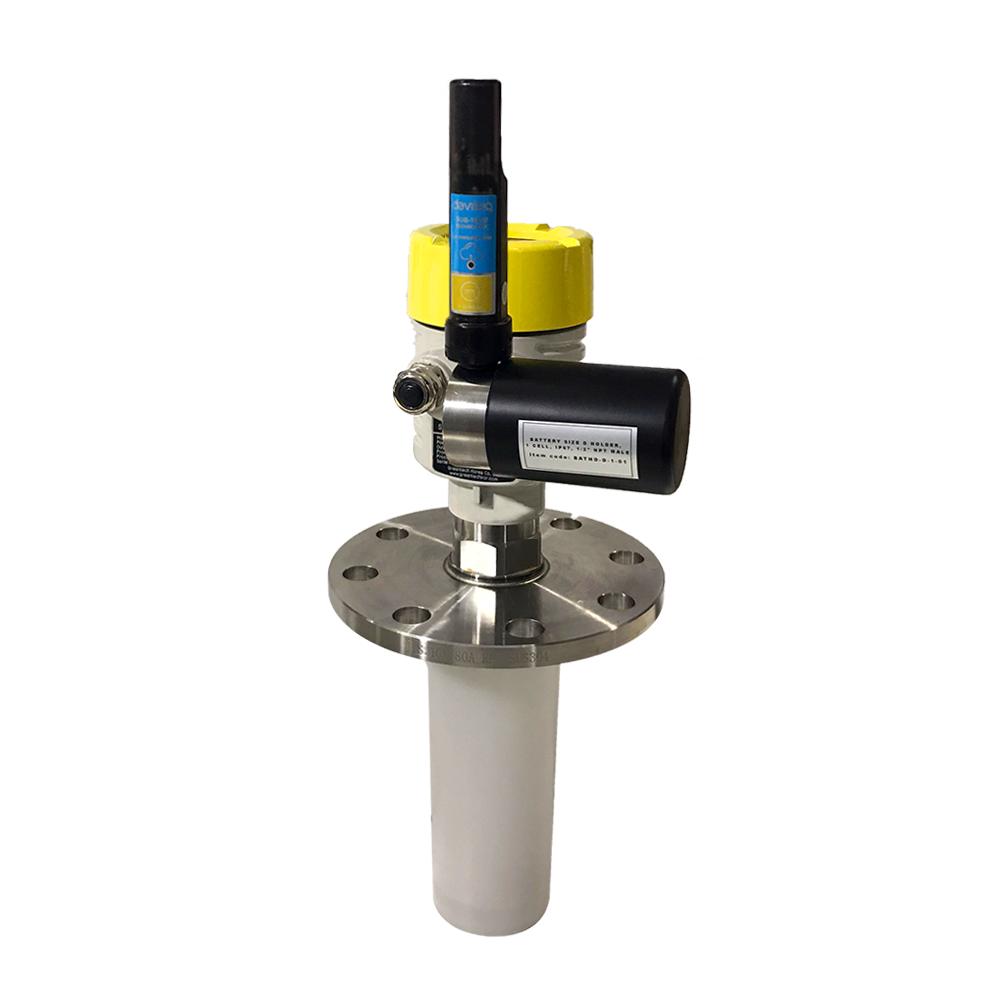
RD2695S-P-B(J)-04-
A3(04)-V-4-L-N-V-6
26GHz RadarLevel transmitter, 78mm PVDF protection tube, SUS304 JIS10K 80A RF Flange, 0-6m
cablibrated range, 4-20mA output, looped power, HART, IP67 aluminum housing
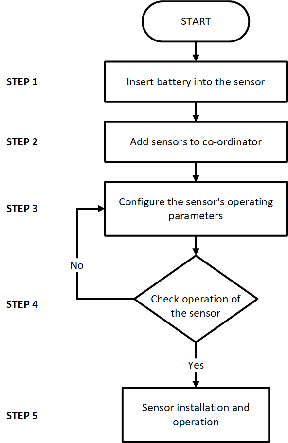
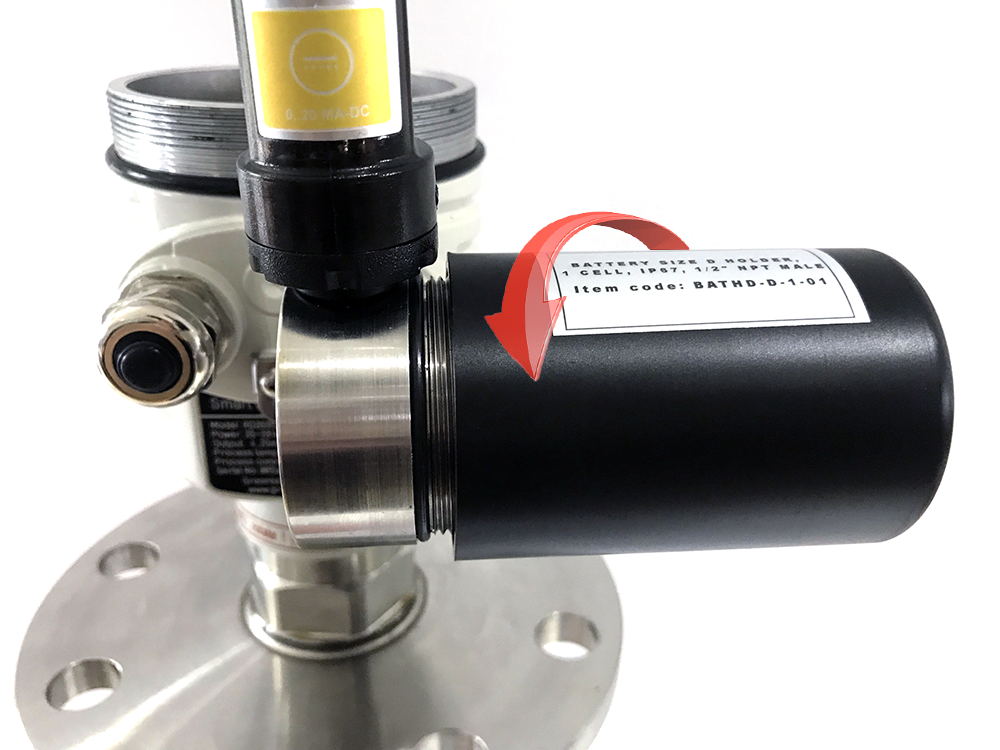
STEP 1: Insert battery into the sensor
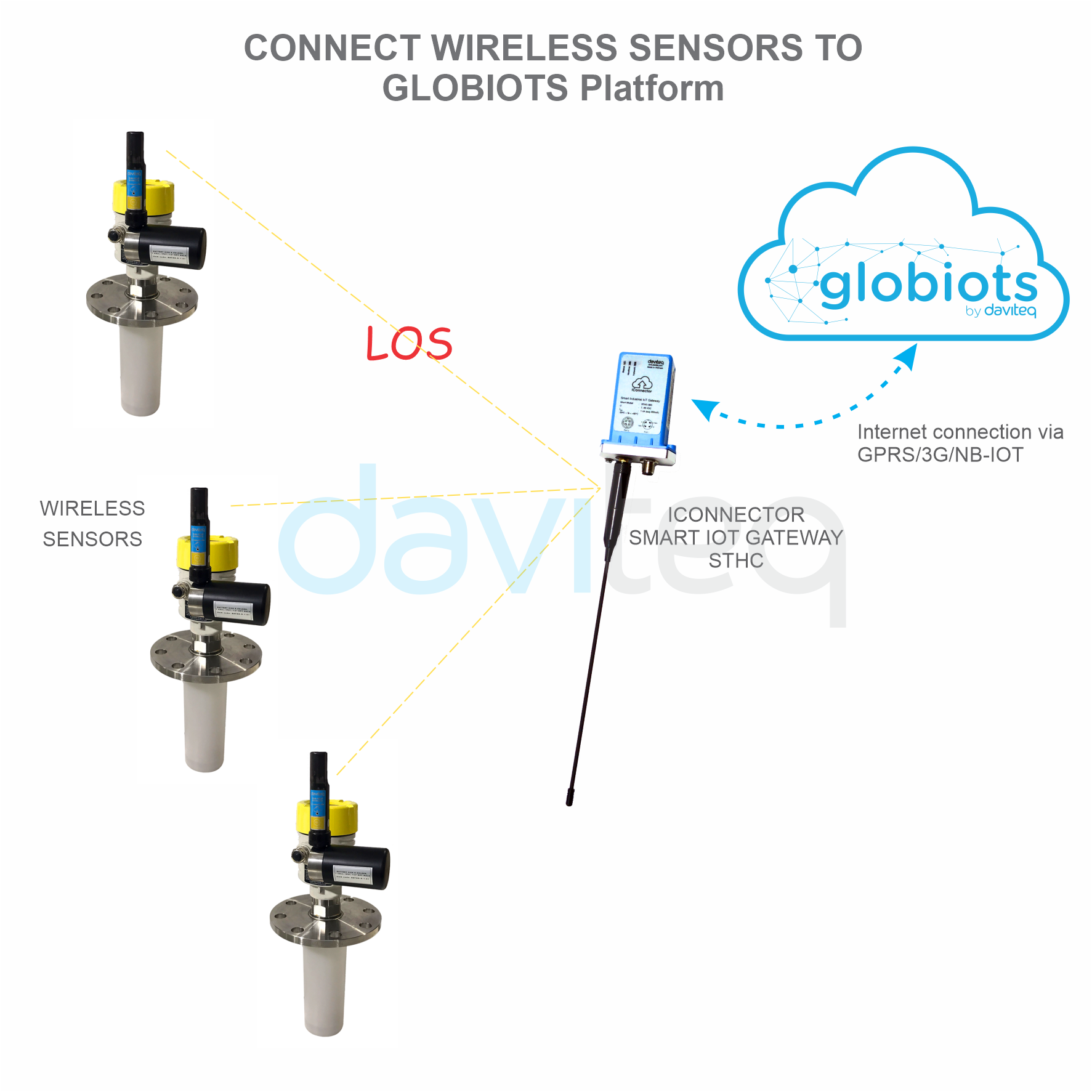
USER GUIDE FOR WIRELESS
RADAR LEVEL METER
This document is applied for the following products
0. Configuration Check List
0.1 Wireless sensor configuration check list

1. Remove the battery cover of the sensor;
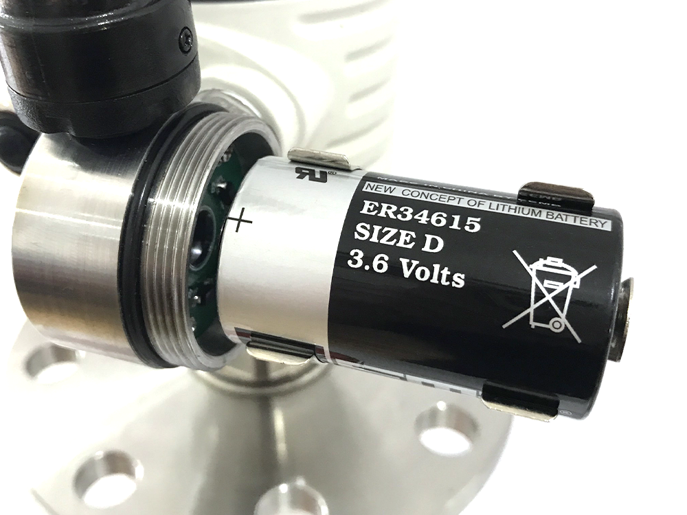
2. Insert a type D battery into the sensor.
STEP 2: Add sensor to co-ordinator
After inserting the battery for the sensor, power on the co-ordinator and bring the co-ordinator closer to the sensor to add the sensor automatically.
STEP 3: Configure the sensor's operating parameters
Use Modbus tool to check added sensors and configure sensor operating parameters.
STEP 4: Check operation of the sensor
1. Use the Modbus tool to check the configurations;
2. Test the configuration settings on the sensor.
STEP 5: Sensor installation and operation
Install sensor on site
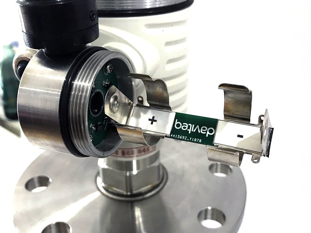
Please note the battery terminals for correct installation
0.2 Radar level meter configuration check list
PLEASE REFER TO THE MANUFACTURER'S INSTRUCTIONS CAREFULLY TO AVOID DAMAGING THE
DEVICE:
USER MANUAL OF RADAR LEVEL METER
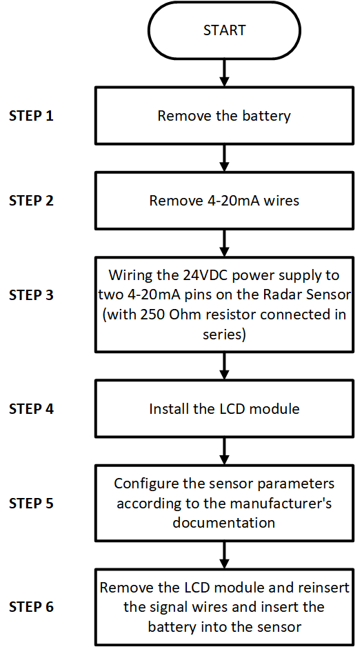
INSTRUCTIONS FOR CONFIGURING SENSORS WITH LCD MODULE

STEP 1: Remove the battery
1. Remove the battery cover of the sensor;
2. Remove a type D battery in the sensor.
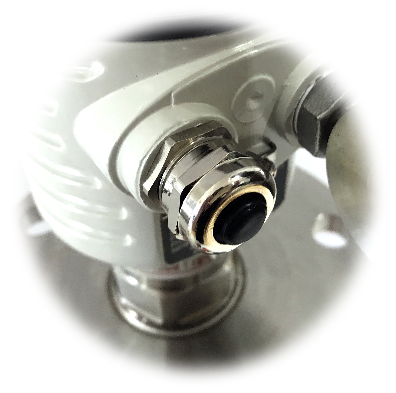
STEP 2: Remove 4-20mA wires
1. Open the radar sensor cover;
2. Remove the 4-20mA wire plugged in the sensor.
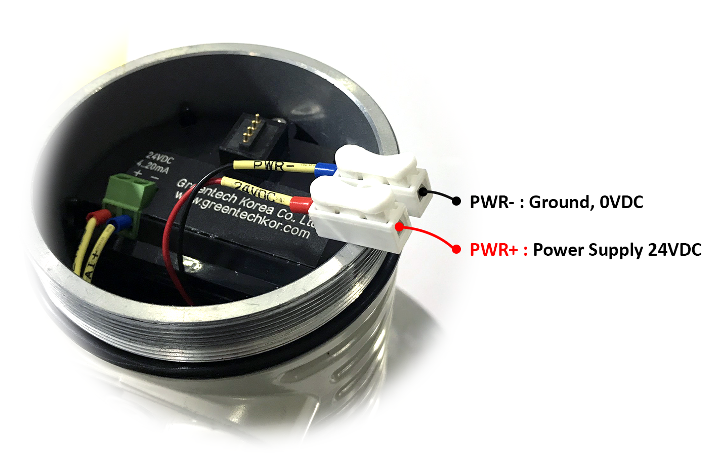
STEP 3: Power supply 24VDC to 2 pins 4-20mA on the Radar Sensor
Power supply 24VDC to 2 pins 4-20mA on the Radar Sensor with 250 Ohm resistor connected in series.
STEP 4: Install the LCD module
Install the LCD module to the radar sensor for configuration.
STEP 5: Configure the sensor parameters according to the manufacturer's documentation
1. Carefully read the manufacturer's instructions before configuring the radar sensor;
2. Power supply 24VDC to the sensor;
3. Configure the parameters of the sensor according to the manufacturer's instructions via buttons
STEP 6: Remove the LCD module and reinsert the 4-20mA signal wires and insert the batteries into the sensor
1. Remove the LCD module of the radar sensor;
2. Remove the power supply cables connected to the 4-20mA port on the sensor;
3. Insert the 4-20mA signal cables of the WS433-MA into 4-20mA port on the sensor;
4. Insert the battery into the sensor.

HW Ver.
FW Ver.
Release Date
Functions Change
2.5
5.0
DEC-2019
Change RF data rate by
button
This is a wireless sensor that measures water level using radar technology. The combination of a high-tech radar level
sensor combined with a wireless sensor using Texas Instrument's advanced Sub-GHz technology enables long-range
transmission with extremely low energy consumption. It will connect 2-way wireless with WS433-CL wireless co-
ordinator to send data and receive configuration. It can be configured with operational parameters such as data
delivery interval, health check cycles ... remotely from the Globiots platform or via the ModbusRTU software (via
WS433-CL). Its default data rate is 50 kbps, which can be converted to 625 bps for increased communication range.
The sensor can operate for up to 10 years with just one AA battery. Sensors can be used to measure water or liquid
levels as well as for measurement in areas such as river level monitoring, chemicals, municipal water supply and
drainage, etc.
Measuring range
0 .. 20mA
Accuracy
0.05% of span
Resolution
1/3000
Temperature drift
< 50ppm
Optional accessories
304SS Adapter PG9/male 1/2"NPT or PG13.5 or M20 to allow direct
mounting on Process instruments or electrical panel
Data speed
Up to 50kbps
Transmission distance, LOS
500m
1. Functions Change Log
2. Introduction
3. Specification
3.1 WS433-MA Specification

Antenna
Internal Antenna, 3 dbi
Battery
01 x AA 1.5VDC, up to 10-year operation, depends on configuration
Frequency Band
ISM 433Mhz, Sub-GHz technology from Texas Instrument, USA
Receiving Sensitivity
-110dBm at 50kbps
International Compliance
ETSI EN 300 220, EN 303 204 (Europe) FCC CFR47 Part15 (US), ARIB
STD-T108 (Japan)
Security Standard
AES-128
Operating temperature of PCB
-40oC..+60oC (with AA L91 Energizer)
Housing
Poly-carbonate, IP67
Installation method
L-type bracket SUS304 , by M4 screws or double-sided 3M tape
(included)
Product dimensions
125x30x30mm
Net weight (without battery)
< 100g
Box dimension
190x50x50mm
Gross weight
140g
Features
Sealed antenna with anti-corrosion cover
Application
Be suitable for strong acids, alkalis, or other strongly corrosive liquids,
or liquids with heavy steam, etc.
Antenna size
** 62mm, corresponding to flange sizes, DN80, DN100
** 96mm, corresponding to flange sizes, DN150, DN200
Measuring range (Maximum)
35m
Process connection
Flange
Process temperature
-60°C … +150°C
Process pressure
-0.1 ~ 1.0MPa
Accuracy
±3mm
Frequency range
26GHz
Explosion proof
Ex ia IIC T6
Enclosure protection grade
IP67
Signal output
4-20mA/ HART (2-wire/ 4-wire), RS485/ Modbus
3.2 RD-2695S Specification
4. Operation Principle
4.1 WS433 Wireless Transmitter
When the sensor sampling time interval is reached, for example 2 minutes, the node will wake up and switch ON

For example: the measurement time is 200mS, after this time, the node will read the value of sensor using I2C, node
will switch OFF power supply to external sensor to save energy.
Once reading the sensor value, the raw data is X, it can be scaled to any engineering value by the following formula:
Y = aX + b
Where
X: the raw value from sensor
Y: the calculated value for parameter 1's value or parameter 2's value
a: constant (default value is 1)
b: constant (default value is 0)
So, if there is no user setting for a and b ==> Y = X
The Y value will be compared with Lo and Hi threshold.
Status bytes of sensor Node
Hi-Byte is error code
Error code
Description
0
No error
1
Just exchange the sensor module but node has not been reset ==>
please take out the battery for 20s then install it again to reset node to
recognize the new sensor module
2
Error, sensor port M12F shorted to GND
3
Error, sensor port M12F shorted to Vcc
4
Error, sensor port M12F shorted each other
Lo-Byte is sensor type
Error code
Description
0
No error
1
Just exchange the sensor module but node has not been reset ==>
please take out the battery for 20s then install it again to reset node to
recognize the new sensor module
2
Error, sensor port M12F shorted to GND
3
Error, sensor port M12F shorted to Vcc
4
Error, sensor port M12F shorted each other
After inserting the battery for the sensor, power on the co-ordinator and bring the co-ordinator closer to the sensor to
add the sensor automatically.
the power supply to supply the energy to external sensor to start the measurement. Depends on the type and
characteristic of external sensor, the sensor will take a certain time to finish the measurement.
4.1.1 Add sensor to co-ordinator

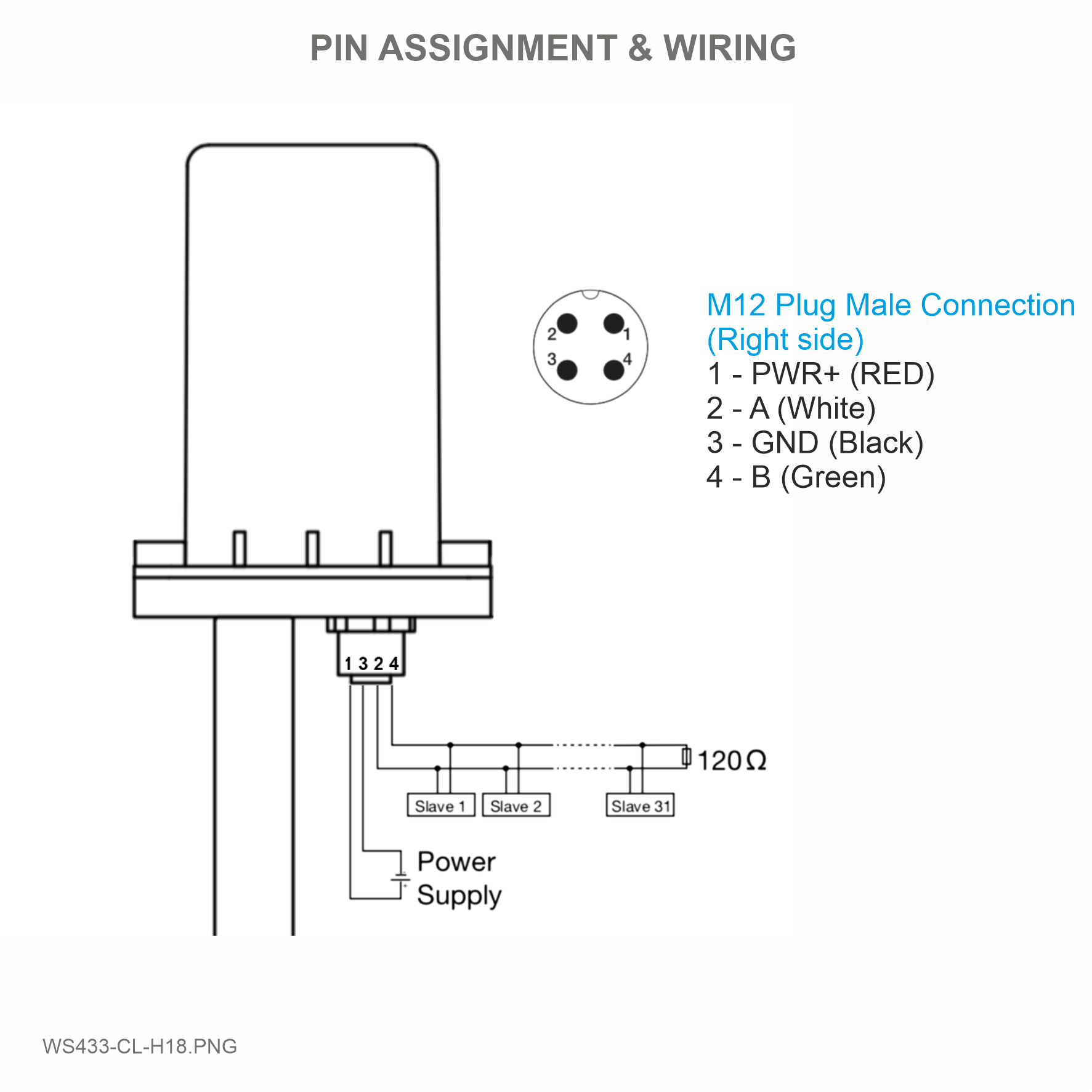
Step 1: After supplying power the Co-ordinator via M12 connector, the Node ID must be registered within the first 5
minutes, up to 40 WS.
Step 2: Bring the wireless sensor closer to the Co-ordinator's antenna then take off the wireless sensor battery, wait
for 5s then insert the battery again. If:
Buzzer plays 1 peep sound, LED blink 1 time, that means registering Node ID on Co-ordinator successfully.
Buzzer plays 2 peep sounds, LED blink 2 times, that this Node ID is already registered.
Node id added in this way will be written to the smallest node_id_n address which is = 0.
Set Rssi_threshold (see RF MODE CONFIG (in the Modbus Memmap of WS433-CL), default -25): The case if Co-
ordinator is on high position and need to add node sensor. We set the sensor as close as possible and set the
Rssi_threshold to -80, -90 or -100 to increase the sensitivity to allow WS433-CL-04 can add sensors at a longer
distance. After that, perform 2 steps of adding sensors and then reset Rssi_threshold = -25.
Enb_auto_add_sensors configuration (see RF MODE CONFIG (in the Modbus Memmap of WS433-CL)): In case
you do not want to turn off the power WS433-CL, you can set Enb_auto_add_sensors = 1, this way we have 5
minutes to add nodes (add up to 40 nodes) . After 5 minutes Enb_auto_add_sensors will automatically = 0.
http://www.daviteq.com/en/manuals/books/long-range-wireless-co-ordinator-ws433-cl/page/user-guide-
for-long-range-wireless-co-ordinator-ws433-cl
Open the cover of sensor then use the push button to set the data transfer speed for the first 30 seconds when the
battery is first installed, after 30 seconds the push button function does not work.
Press and hold the button for 2 seconds => LED blinks once => Release the button to set Data rate RF 50kbps
If you do not hear the "Peep" sound, please disconnect the power the co-ordinator, wait a few minute and try
again.
Memmap resgisters
You can download Modbus Memmap of WS433-CL with the following link:
https://filerun.daviteq.com/wl/?id=BKEaUzdArkoc0Hc7nfpRShdPVToVrqQZ
4.1.2 Add sensor node into WS433-CL-04 (1) through intermediate
WS433-CL-04 (2) and Modbus
In case the sensor need to be added to WS433-CL-04 (1) has been installed in a high position, the
sensor cannot be brought close to WS433-CL-04 (1). For more details:
4.1.3 Button Function

Press and hold the button for 5 seconds => LED blinks twice => Release the button to set Data rate RF 625bps
Press and hold the button for 10 seconds => LED blinks 3 times => Release the button to reset RF parameters
(frequency, RF output power, data rate), if held for more than 30 seconds then the button function does not
work.
First, you need to prepare
Reset default WS433:
Frequency: 433.92 MHz
RF transmit power: 15 dBm
RF data rate: 50 kbps
4.1.4 Configure sensor parameters in Co-ordinator
Num of Node will indicate the number of nodes managed by WS433-CL.
Every time a node is added, the Num of Node will increase by 1.
Every time a node is deleted, the Num of Node is reduced by 1.
Writing Num of Node = 0 will delete all 40 node ids to 0.
If you want to delete a node id, then write it = 0 with the Write function is 16 and the Read function is 3.
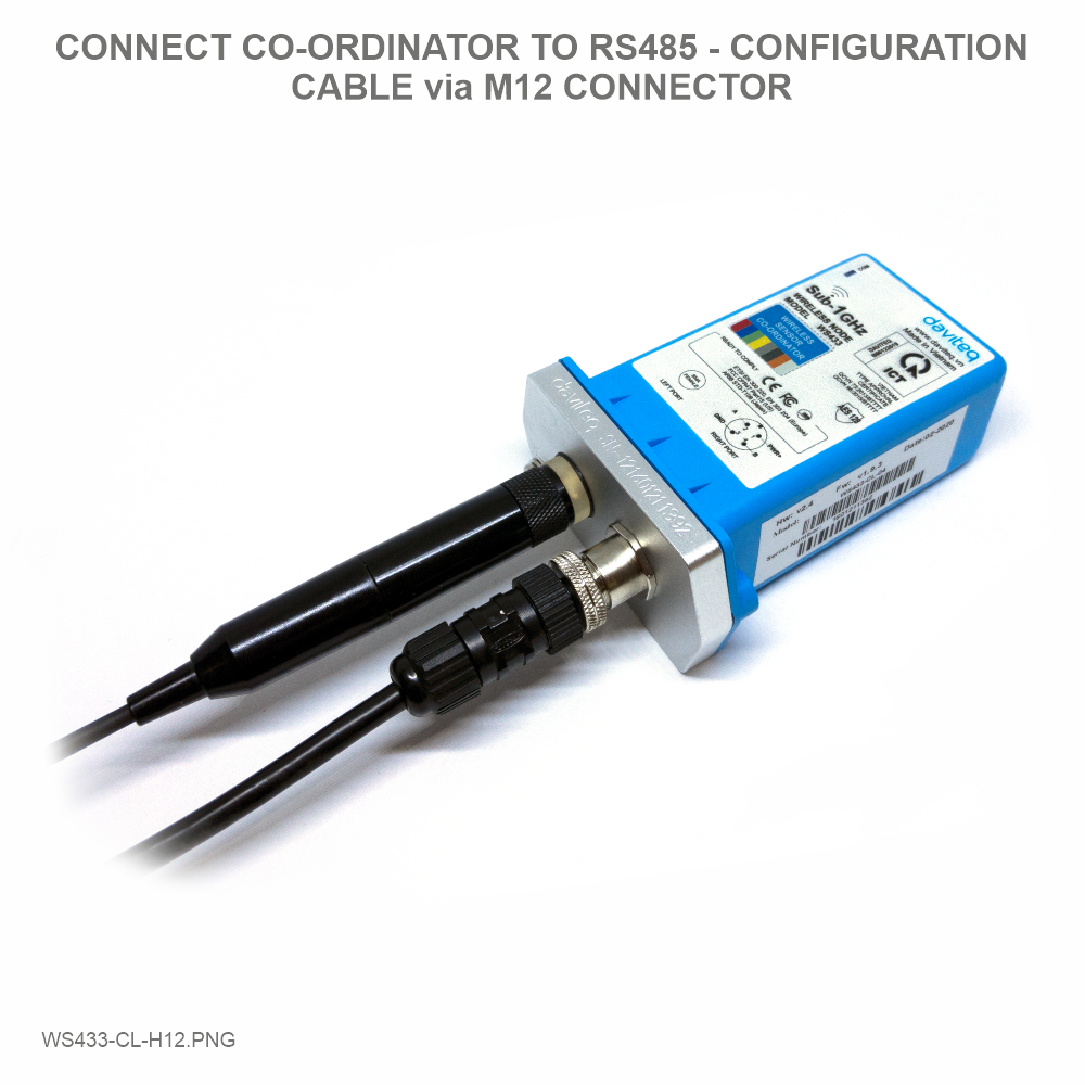
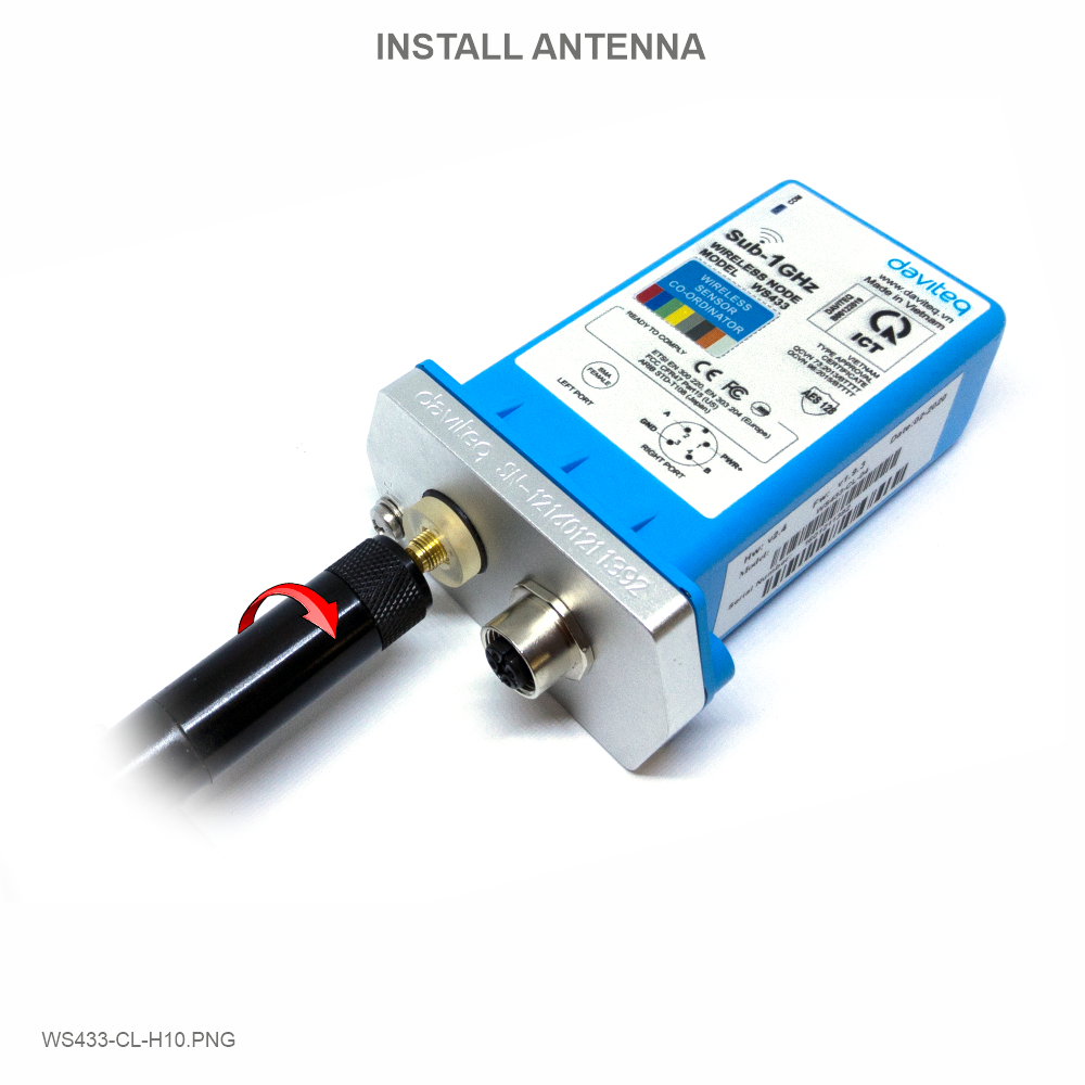
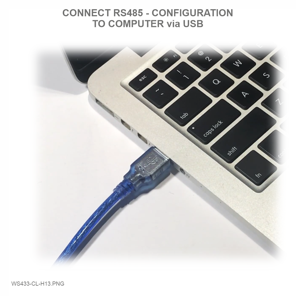
Step 1: Connect Antenna, RS485 - configuration cable and power supply co-
ordinator

You can download Daviteq Modbus Configuration Tool with the following link:
https://filerun.daviteq.com/wl/?id=bU88UgTMDNPIXjafxwxQeU89JtAoXEZR
Unzip file and run file application "Daviteq Modbus Configuration Tool Version 1.1"
Step 2: Open Modbus tool on PC
Template File: https://filerun.daviteq.com/wl/?id=hgrjOg3wwvyrvAZ54p8iZiFpDyXTcnec
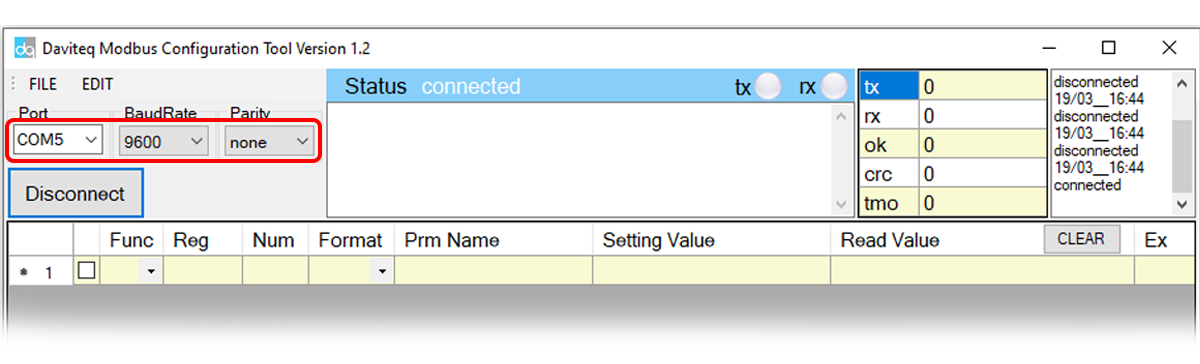
How to use the Modbus configuration software

Choose COM Port (the Port which is USB cable plugged in)
Set the BaudRate: 9600, Parity: none
Click “ Connect “ untill the Status displays “disconnected” to “connected“. It means the WS433-CL-04 is
being connected with computer;
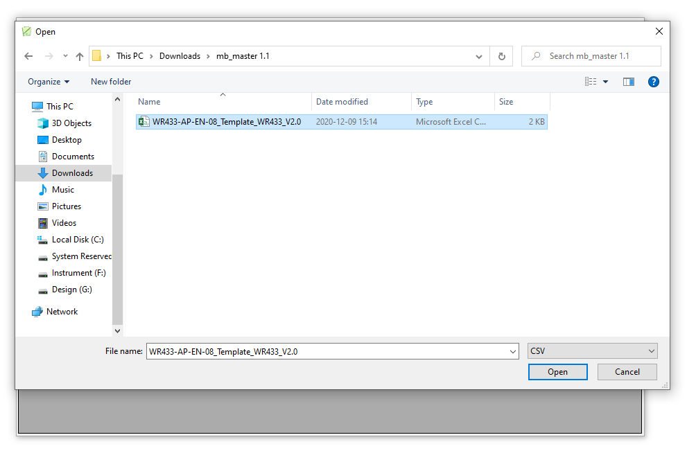
Next, we need to import the configuration file for WS433-CL-04 by importing the csv file: Go to MENU: FILE /
Import New / => select the template file.
Use Modbus tool to check added sensors and configure sensor operating parameters.
In the memmap file, refer to the Memmap of WS433-AI sheet to configure the sensor's operating parameters
accordingly.
Step 3: Configure the sensor's operating parameters.
Memmap resgisters
You can download Modbus Memmap of WS433-CL-FW with the following link:
https://filerun.daviteq.com/wl/?id=WBbGm89AToHWyvIyMOc780N1KmjfUr3Y
The reference memmap addresses are based on the order of the sensors added in the Memmap file
above

Below are examples of some typical sensor parameters:
Function
Code
(Read)
Function
Code
(Write)
# of
register
Byte Size
Description
Value
Range
Default
Format
Property
Explanation
4
1
2
%Battery
of sensor
Node
10,30,60,99
uint16
Read
Battery
level, only
04 levels:
10%, 30%,
60% and
99% (full).
When 10%
==> Need
to replace
the battery
4
2
4
Analog
value 1 of
sensor
Node
(parameter
1)
float
Read
Value from
Analog
input
sensor. This
value is
parameter
1 of a
wireless
sensor node
4
2
4
Value of
parameter
2 of sensor
Node
float
Read
Same value
as
parameter
1
3
1
2
Data status
of Node
0-9, 99
byte
Read
0-9:
Interval
updated
data
99:
Disconnected
3
1
2
RF Signal
strength of
Node
0-4
byte
Read
From 0 to 4
with 0 is
being lost
connection
RF and 4 is
the
strongest
RF
3
16
1
2
Cycle_wakeup
1-3600(s)
120
uint16
Read/Write
Every time
interval of
Cycle_wakeup,
sensor node
would ONLY
send data
to co-
ordinator if
the new
measured
value was
changed
more than
the Delta
value of the
last
measured
value.
Default
Cycle_wakeup
is 120
seconds
3
16
1
2
Cycle_healthsta
60-7200(s)
600
uint16
Read/Write
Every time
interval of
Cycle_healthsta,
sensor node
will
absolutely
send data
to co-
ordinator
regardless
any
condition

3
16
2
4
Radio
frequency
433.05-
434.79, 433
Mhz
433.92
float
Read/Write
Configure
the
operating
frequency
of wireless
sensor by
Co-
ordinator,
should be
configured
from
433.05-
434.79
MHz, only
for
advanced
users
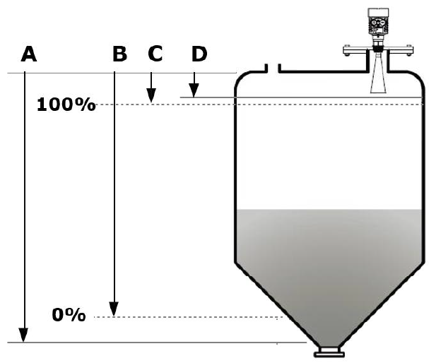
The Radar Level Transmitter antenna emits narrower micro wave pulses which will be transmitted via the antenna. The
micro wave will be reflected back after touching the surface of a medium, then antenna system will receive it and
transmit it into the electrical circuit, which will be automatically turned into the level signals.
A: Setting measuring range
B: Low level adjustment
C: High level adjustment
D: Dead zone
Measuring reference: the bottom surface of threads or the sealing surface of a flange.
4.2 Radar Sensor RD-2695S
Note:
When using the radar level transmitter, must keep the highest level of medium out of the dead zone
(see area D shown in the drawing)

To maximize the distance of transmission, the ideal condition is Line-of-sight (LOS) between the Wireless sensor and
Gateway. In real life, there may be no LOS condition. However, the Wireless sensor still communicates with Gateway,
but the distance will be reduced significantly.
PLEASE REFER TO THE MANUFACTURER'S INSTRUCTIONS CAREFULLY TO AVOID DAMAGING THE
DEVICE:
USER MANUAL OF RADAR LEVEL METER
INSTRUCTIONS FOR CONFIGURING SENSORS WITH LCD MODULE
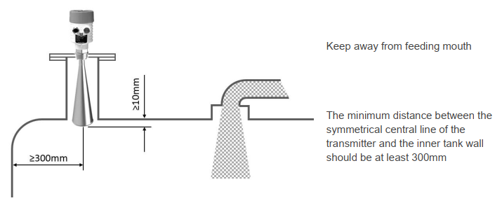
5. Wireless sensor installation
5.1 Installation location
ATTENTION:
DO NOT install the Wireless sensor or its antenna inside a completed metallic box or housing, because the RF
signal can not pass through the metallic wall. The housing is made from Non-metallic materials like plastic,
glass, wood, leather, concrete, cement…is acceptable.

Step 1: Remove the battery cover of the sensor
Step 2: Insert a type D battery into the sensor
Insert the power cord into the sensor via Cable Gland
5.2 Power supply and battery installation
5.2.1 battery installation
Recommends using type D batteries for wireless sensors.
ATTENTION:
REVERSED POLARITY OF BATTERIES IN 10 SECONDS CAN DAMAGE THE SENSOR CIRCUIT !
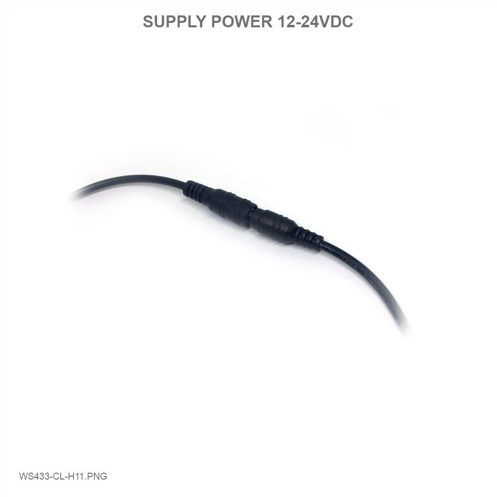
5.2.2 Power Supply


1
The status LED of wireless sensor
doesn't light up
No power supply
Configuration function of
the LED is not correct
Check that the battery is
empty or not installed
correctly
Reconfigure the led light
function exactly as
instructed
2
Wireless sensor not connected to
co-ordinator
No power supply
The configuration function
of the RF data rate is
incorrect
Check that the battery is
empty or not installed
correctly
Reconfigure the RF data
rate with the button
according to the
instructions
Manufacturer
Daviteq Technologies Inc
No.11 Street 2G, Nam Hung Vuong Res., An Lac Ward, Binh Tan Dist., Ho
Chi Minh City, Vietnam.
Tel: +84-28-6268.2523/4 (ext.122)
Email: info@daviteq.com | www.daviteq.com
Distributor in Australia and New Zealand
Templogger Pty Ltd
Tel: 1800 LOGGER
Email: contact@templogger.net
Revision #16
Created Tue, Nov 3, 2020 8:38 AM by Kiệt Anh Nguyễn
Updated Wed, Dec 9, 2020 8:49 AM by Kiệt Anh Nguyễn
7. Support contacts
This manual suits for next models
4
Table of contents
Other daviteq Measuring Instrument manuals

daviteq
daviteq WS433-CO2 User manual

daviteq
daviteq WS433-M12F-ATH User manual

daviteq
daviteq WSSFC-G4F-NH3 User manual

daviteq
daviteq MBRTU-TBD User manual

daviteq
daviteq WS433-ULC User manual

daviteq
daviteq MBRTU-SAL User manual

daviteq
daviteq Sigfox WSSFC-PPS User manual

daviteq
daviteq CAP10CNC User manual
Popular Measuring Instrument manuals by other brands


FASANO TOOLS
FASANO TOOLS CAT III 300V manual

ADVANTEST
ADVANTEST R3465 Series Operation manual

Electro Industries/GaugeTech
Electro Industries/GaugeTech Shark 100 Installation and operation manual

CubiScan
CubiScan 125 Operation manual

OHAUS
OHAUS Defender I-D33P15B1R1 instruction manual

Flexim
Flexim FLUXUS F601 quick start guide


