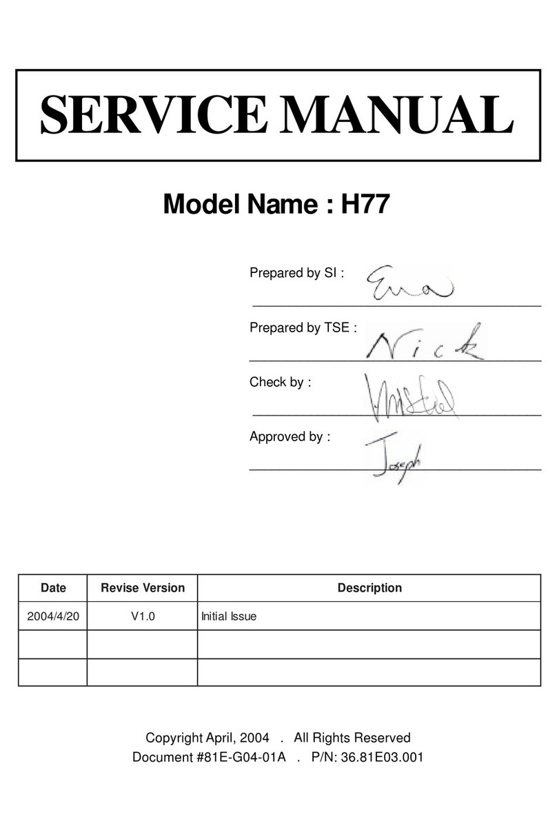
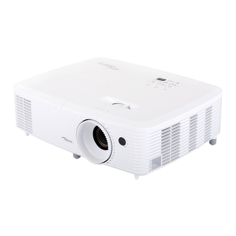
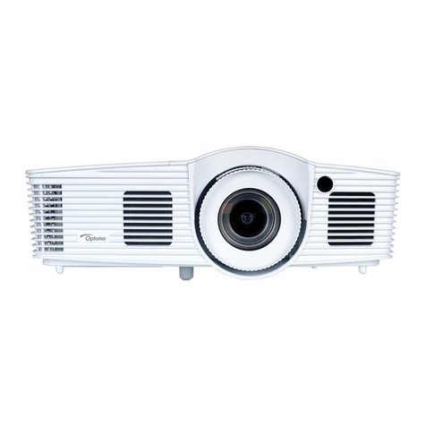
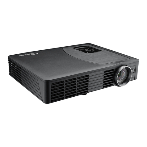
Optoma H76 User manual

Model Name : H76
SERVICE MANUAL
etaDnoisreVesiveRnoitpircseD
42/7/30020.1VeussIlaitinI
Prepared by SI :
________________________________________
Prepared by TSE :
________________________________________
C eck by :
________________________________________
Approved by :
________________________________________
Copyrig t July, 2003 . All Rig ts Reserved
Document #866-G04-01A . P/N: 36.86604.001

This manual is applied to H76 TI 0.79 DMD / 12deg / 1280x720 / XGA Home Theater Projector
with digital imaging functionality based on Digital Micro-mirror Device (DMD) technology. Its the
mode of single Panel, 250 watt Philips UHP lamp and 1280(H) x 720(V) resolution. The manual
gives you a brief description of basic technical information to help in service and maintaining the
product.
Your customers will appreciate the quick response time when you immediately identify problems
that occur with our products. e expect your customers will appreciate the service that you offer
them.
This manual is for technicians and people who have an electronic background. Send the product
back to the distributor for repairing and do not attempt to do anything that is complex or is not
mentioned in the troubleshooting.
NOTICE :
The information found in this manual is subject to change without prior notice. Any subsequent
changes made to the data herein will be incorporated in further edition.
Copyright 2003, July
All Rights Reserved
Manual Version 1.0
Document # 866-G04-01A
Preface
H76I

H76II
Table of Contents
Chapter 1 ntroduction 1-1
Product Hig lig ts 1-1
Mac anical Specifications 1-2
Electrical Specifications 1-2
Optical Specifications 1-3
Environmental 1-4
Chapter 2 Disassembly Procedure 2-1
Disassemble Lamp Module 2-1
Disassemble Top Cover 2-2
Chapter 3 Troubleshooting 3-1
Equipment Needed 3-1
Main Procedure 3-1
Chapter 4 Function Test and Alignment Procedure 4-1
Product 4-1
Test Equipment 4-1
Test Condition 4-1
Test Display Modes & Pattern 4-2
Inspection Procedure 4-6
Chapter 5 Firmware Upgrade Procedure 5-1
Equipment Needed 5-1
Setup Procedure 5-2
Firmware Upgrade Procedure 5-3
Chapter 6 DDC Key-in Procedure 6-1
Equipment Needed 6-1
Setup Procedure 6-2
DDC Key-in Procedure 6-3
Chapter 7 Appendix 7-1
Serial number system definition 7-1

H761-1
Chapter 1
Introduction
1-1 Product Highlights
- One 0.79" Mustang DMD projection system with700 ANSI umen (Min-Engineering
spec), 80% uniformity minimum (ANSI)
- Contrast (FOFO) : 1400 : 1 (Min Engineering spec)
- 250 Watt Phi ips UHP Lamp 1500hrs (user rep aceab e)
- High efficiency coo ing system with system acoustic noise eve 30dBA ( Average )
- Lens Up/Down 100% Shift construction
- 4 Adjustab e Feet
- Dimensions : Externa Max size 430mm x 305mm x 135mm (without s iding cover)
- Power focus projection and power zoom ens 1.35X
- RGB co or whee spinning at 120Hz (TBD)
- Computer capabi ity up to UXGA 60Hz for Ana og & SXGA 60Hz for Digita Inputs
- NTSC/PAL/SECAM video capabi ity with S-video / composite / component, and HDTV
(480i/p, 576i/p, 720p, 1080i)
- Separate y R/G/B/H/V BNC input supported.
- Auto detection of computer signa input.
- Auto Image.(Auto-tracking /frequency /position adjustment)
- Automatica y saves adjustments for future use
- On-screen menu with 9 anguages
- On Screen amp ife timer
- One DVI PC-data input ( Inc uding Ana og and Digita RGB signa )
- Wire ess remote contro er
- Adaptive vo tage contro fan speed.
- Support HDCP function

H761-2
1-2 Mechanical Specifications
- Dimensions(WxHxD) - 16.9(W) x 12.0(D) x 5.3(H) inches ( 430 x 305 x 135 mm)
- Weight : < 16.5 bs. ( 7.49 Kg )
- Coo ing System - Advanced Air F ow
Three motor FANs with system acoustic 30dB(A) (Average)
Temperature contro circuits with Fan speed
- Cabinet : Provides space for PCB boards, FAN, optica engine, power supp y,
- Co or : Ivory white or ebony b ack
- Lamp Door Protection : Lamp Power Supp y shut off automatica y when door open
1-3 Electrical Specifications
Power Supp y Universa AC 90264V~ 50-60 Hz with PFC input
250W for Phi ips UHP Lamp @ norma operation
Input signa spec. - Hsync Frequency 31.5 ~ 100 kHz
- Vsync Frequency 43 ~ 85 Hz
- Video Signa RGB (PC)
Ana og RGB 0.7Vp-p, 75 ohm
Ana og RGB 1Vp-p, 75 ohm, Sync. Signa
Separate TTL H,V Sync.
Composite TTL Sync.
- Video
Composite video 1Vp-p,75 ohm
S-video Luminance 0.714Vp-p,75 ohm
Chrominance 0.286Vp-p,75 ohm

H761-3
1-4 Optical Specifications
- Projection ens : f = 28.3 ~ 38.2 mm, F/2.4, 1.35X Manua Zoom Lens.
- Projection Image Size : 21 to 282 Diagona
- Throw Distance : 3.28 ft to 32.80 ft/ 1.0 m to 10m.
- Throw Ratio : 1.6~2.16 (Projection Distance/Image Width)
- Brightness : Typica 800 m /Minimum 700 m
- Contrast : Typica 1600:1 /Minimum 1400:1
- Uniformity : Typica ANSI 85% /Minimum 80%
ecnatsiDnoitcejorPecnatsiDnoitcejorP ecnatsiDnoitcejorP ecnatsiDnoitcejorPecnatsiDnoitcejorP).xaM(eziSegamI).xaM(eziSegamI ).xaM(eziSegamI ).xaM(eziSegamI).xaM(eziSegamI).niM(eziSegamI).niM(eziSegamI ).niM(eziSegamI ).niM(eziSegamI).niM(eziSegamI
"73.93/'82.3/m0. "32.82/'53.2/m27.0"9.02/'47./m35.0
"60.95/'29.4/m5. "53.24/'35.3/m80. "73.3/'6.2/m08.0
"47.87/'65.6/m0.2"64.65/'7.4/m34. "38.4/'94.3/m60.
"58.69/'4.6/m0.5"6.4/'67./m95.3"65.40/'7.8/m76.2
"7.393/'8.23/m0.0 "23.282/'35.32/m7.7"3.902/'34.7/m3.5
1-5 En ironmental
- Temperature Operating : -5°C 35°C
Storage : -10°C 60°C
- Maximum Humidity Operating : -5°C 35°C , 80%RH (Max.), non-condensing
Storage : -10°C 60°C , 80%RH (Max.), non-condensing
- Acoustic noise eve 30 dB(A) Standard (Typica , Under 23+/-2oC), noise measure-
ment fo ows ISO 7779, A-weighted sound pressure eve mea-
surement
- Unit temperature imitation : Temperature of externa parts
- Lamp ife 1500 hours min. , 50% survia rate
- A titude Operating : 0~2,500 ft 5°C~35°C
2,500~5,000 ft 5°C~30°C
5,000~10,000 ft 5°C~25°C
Storage : < 40,000 ft
- MTBF Operating more than 10,000 hrs (80% confidence eve )
- Re iabi ity Test Refer 07- 2016 Re iabi ity Test Procedure ;
H762-1
Chapter 2
Disassembly Procedure
2-1 Disassemble Lamp Module
1. Unscrew 1 screw to remove Lamp Cover from inside to outside, then pull it up.
2. Loosen 3 screws to remove Lamp Module.
1
2

H762-2
1. Remove 8 screws from the ottom for the top cover.
Remove the FFC ca le when you pull up the top cover.
2-2 Disassemble Top Cover
2. Remove 2 screws from the Top Cover.
3. Remove 4 hex screws and then take off I/O Panel
1
2
3
1

H762-3
5. Remove 9 screws (85.1A623.060).
6. Remove FFC ca le (42.85801.001) from Keypad to M/B.
7. Remove 4 screws (85.1A623.060) from Thermal Board and remove 9 hex screws (61.
86627.001) and 9 springs (61.87208.001) from Main Board.
8. Remove 4 Flat screws (85.4A323.050) from Lamp Housing Holder (51.86604.001).

H762-4
10. Remove 2 screws (85.1A623.060).
11. Remove 4 screws (85.1A623.060).
9. Unplug 9 wires from Thermal Board.
To Axial Fan
(3 Pin white CNNT)
To Photo Sensor
(3 Pin white CNNT)

H763-1
Chapter 3
Troubleshooting
3-1 Equipment Needed
H76 Projector
DVI to VGA Cable, Power Cord
PC (Personal Computer)
V deo Input
Screw Dr vers
3-2 Main Procedure
Connect Power cord, analog
or d g tal s gnal, then turn
power on
Start
Is Image OK ? B. Image Performance
Troubleshoot ng
C. Funct on
Troubleshoot ng
Yes
Is Lamp l ght on ? A. Power
Troubleshoot ng
Yes
Yes
Is funct on OK?
No
No
No
Cont nue

H763-2
No Fault Found
Is Remote
Control OK?
E.
Remote Control
Troubleshoot ng
Yes
End
Cont nue
No
H7 Projector Signal Test
Accord ng to the s gnal of Lamp, Temp and Power LED to dec de the funct on error as follows :
1. Turn on the power and push down the Power LED button, appear Power LED s gnal but lamp
cant l ght up.
Cause : Projector over heat.
2. Turn on the power and Temp s gnal s fl cker.
Cause : Thermal Sensor detect the projector s over heat.
3. Temp and Power LED s gnal are fl cker.
Cause : Thermal error or Fan fa led.
4. Lamp and Power LED s gnal are fl cker.
Cause : Lamp NG.

H763-3
3-2.1 A. Power Troubleshooting
Is LED
nd cator
OK?
Check power
cord &
nput power
voltage
Lamp Cover
assembly OK?
Reassembly
Lamp
Cover
Start
End
Supply
Power
Source
Is Fan work ng?
No Yes No
No
Yes
Yes
Change
Power Supply
Module
Change
Front-End
Board
Yes
No
Is Lamp l t?
No Change
Thermal
Board
Change Fan
Module
No
Change
Lamp
Ballast
Change
Front-End
Board
No
Yes
No Fault Found
Can hear the sound
of lamp turn on?
(Da.Da.Da.)
No
No
Yes
Change Lamp
Module

H763-4
3-2.2 B. Performance Troubleshooting
Start
Have mage?
Un form ty OK?
Is color OK?
Have l ne bar?
Have garbage
pattern?
Dot defect snt
compl ant w th
the spec.?
No Change
Front-End
Board
No Change
DMD Module
Yes No Change
DMD Module
No Change
Eng ne Module
Change
Front-End
Board
No Change
DMD
Module
No Opt cal
Eng ne
Yes Change
DMD Module
Yes Adjust
frequency
Yes
No
Yes
Yes
No
No No
Color Adjust
Procedure
* Note 1
Have no se? Yes Adjust
track ng
No
End
No
Change
Front-End
Board
No Change
Front-End Board
No Change
DMD Module
No Change
Front-End Board
No Fault Found

H763-5
3-2.3 C. Function Troubleshooting
Does OSD
show up?
Start
Is KeyPad
Board OK?
No Yes Is Remote
Controller
OK?
Yes Change
Front-End
Board
Change
Key Pad Board
Can funct on
be adjusted?
Change
Front-End Board
No
Yes
Yes
No
End
No Fault Found
Change
Remote Control
No

H763-6
3-2.4 E. Remote Control Troubleshooting
Start
End
Does the Remote
Funct on work?
No
Replace the battery
Yes
No
Change Remote Control
No
Change Front-End Board
Yes
Yes

H764-1
Chapter 4
Function Test & Alignment Procedure
4-1 Product
- H76
4-2 Test Equipment
- IBM PC with XGA resolution (Color Video Signal & Pattern Generator
- VCR with Multi-system(NTSC/PAL/SECAM
- Chroma meter Minolta CL-100
4-3 Test Condition
- Circumstance Brightness : Dark room less than 10 lux
- Inspection Distance : 2.0m
- Screen Size : 60 inches diagonal (wide
- Before function test and alignment, each H76 should be run-in and warmed-up for
at least 30 minutes with following conditions.
1. In room temperature
2. With cycled display colors (R,G,B,White
3. With cycled display modes
640*350 (H=31.5 KHz, V=70 Hz
640*400 (H=37.9 KHz, V=85 Hz
640*480 (H=37.9 KHz, V=72 Hz
720*400 (H=31.5 KHz, V=70 Hz
800*600 (H=53.7 KHz, V=85 Hz
800*600 (H=37.9 KHz, V=60 Hz
1024*768 (H=48.4 KHz, V=60 Hz
1024*768 (H=68.7 KHz, V=85 Hz
- Test Display Mode & Pattern (Refer to 4-3.1 & 4-3.2
- Function Test and Alignment Procedure

H764-2
4-4 Test Displa Modes & Pattern
4-4.1 Compatible Modes
ytilibitapmoC noituloseR )zH(cnyS-V )zHK(cnyS-H
AGV053*046075.13
AGV053*046589.73
AGV004*046075.13
AGV004*046589.73
AGV084*046065.13
AGV084*046279.73
AGV084*046575.73
AGV084*046583.34
AGV004*027075.13
AGV004*027589.73
AGVS006*008652.53
AGVS006*008069.73
AGVS006*008271.84
AGVS006*008579.64
AGVS006*008587.35
AGX867*42014.345.53
AGX867*4201064.84
AGX867*4201075.65
AGX867*4201570.06
AGX867*4201587.86
AGXW027*082106
AGXS4201*08210646
AGXS4201*08215708
AGXS4201*0821581.19
AGXU0021*00610657
"31CLCAM084*04666.6689.43
"31IICAM084*04686.6653
"61CAM426*23855.4737.94
"91CAM867*42015742.06
Analog :

H764-3
ytilibitapmoC noituloseR )zH(cnyS-V )zHK(cnyS-H
CAM078*251160.5786.86
4GCAM084*0460653.13
4GCAM084*04602130.86
4GCAM867*420102190.79
VDCAMi084*04671106
VDCAMi006*0085906
VDCAMi867*42015706
VDCAMi078*25115794.86
VDCAMi069*08215757
Analog :
ytilibitapmoC noituloseR )zH(cnyS-V )zHK(cnyS-H
AGV053*046075.13
AGV053*046589.73
AGV004*046075.13
AGV004*046589.73
AGV084*046065.13
AGV084*046279.73
AGV084*046575.73
AGV084*046583.34
AGV004*027075.13
AGV004*027589.73
AGVS006*008652.53
AGVS006*008069.73
AGVS006*008271.84
AGVS006*008579.64
AGVS006*008587.35
AGX867*4201345.53
AGX867*4201064.84
AGX867*4201075.65
AGX867*4201570.06
AGXW027*082106
AGXS4201*0821060.46
Digital :

H764-4
metI tnetnoCtseT nrettaP noitacificepS krameR
1gnikcarT&ycneuqerFerioMeniLeniF.esionyvawlausivetanimilE1erugiF
2ssenthgirB/tsartnoCelacSyarG.elbahsiugnitsidebdluohsslevelyarG2erugiF
3etihWdnaB,G,R
ecnamrofreProloC
dnaB,G,R
roloCetihW .lamronebdluohsrolocB,G,RhcaE
F
i
erug
6~3
4
&ytimrofinUneercS
rekcilF etihWlluF.cepsehthtiwtnailpmocebdluohS F
i
erug
6
5lexiPhsimelB/daeD
,etihW,B,G,R
,081eulB,kraD
03yarG
dluohsslexiphsimelb/daedfosrebmunehT
.cepsehthtiwtnailpmoceb erugiF
9~3
6
yradnuoB
emarFyradnuoB
ebdluhsoedivfonoitisop.treVdna.zroH
.emarfneercsehtnihtiwebotelbatsujda F
i
erug
7
4-4.2 Function Test Displa Pattern
Fine Line Morie Pattern (Figure 1 Contrast & Brightness (Figure 2
R. Color Pattern (Figure 3 G. Color Pattern (Figure 4
Other manuals for H76
2
Table of contents
Other Optoma Projector manuals

Optoma
Optoma Optoma TXR774 User manual

Optoma
Optoma HD33 User manual

Optoma
Optoma Optoma EP7155 User manual

Optoma
Optoma TX7155 User manual

Optoma
Optoma DS216 User manual

Optoma
Optoma EH505-B User manual

Optoma
Optoma EP780 User manual

Optoma
Optoma GT700 User manual

Optoma
Optoma HD91 User manual

Optoma
Optoma TX779P-3D User manual

Optoma
Optoma Optoma EP1691 Technical manual

Optoma
Optoma EW610ST User manual

Optoma
Optoma GT750ST User manual

Optoma
Optoma E1P2A2F6E1Z1 User manual

Optoma
Optoma 515ST Series User manual

Optoma
Optoma TW7755 User manual

Optoma
Optoma Pico PK320 User manual

Optoma
Optoma DX602S User manual

Optoma
Optoma PRO8000 Technical manual

Optoma
Optoma EP753 User manual