Optoma EP737 Instruction manual

0-1 EP737 SERVICE MANUAL
Introduction Fundamental Principle Mechanical Construction Procedure of Disassembly Function of Boards Specifications
Troubleshooting Function Test and Alignment Procedure Firmware Upgrading Procedure DDC Key-In Procedure Appendix
This manual is prepared for the maintenance service for EP737 Micro-portable XGA DLP Projector.
Maintenance procedures described in this manual are intended to isolate faulty parts and replace
them in the field. It also aims to serve as a guide in procuring replacement parts for this product.
This manual is copyrighted and all rights are reserved. This product may not, in whole or in part,
be copied, photocopied, translated or reduced to any electronic or machine readable form without
prior written consent except for copies retained by the purchaser for backup purpose.
This manual includes system overview, major system assembly, components description, and
the Troubleshooting making explanations on how to detect errors. It also includes a flow chart for
checking or correcting faults.
No warranty or representation, either expressed or implied, is made with respect to this
documentation, its quality, performance, merchantability or fitness for particular purpose.
No event that the vendor will be liable for direct, indirect, special, incidental or consequential
damages arising out of the user or inability to use this product or documentation.
¡NOTICE :
The information found in this manual is subject to change without prior notice. Any subsequent
changes made to the data herein will be incorporated in further edition.
Copyright 2002, October
All Rights Reserved
Manual Version 1.0
Document # 863-G04-01A
P/N : 36.86305.001
Preface

0-2 EP737 SERVICE MANUAL
Introduction Fundamental Principle Mechanical Construction Procedure of Disassembly Function of Boards Specifications
Troubleshooting Function Test and Alignment Procedure Firmware Upgrading Procedure DDC Key-In Procedure Appendix
Introduction....................................................................................................................... 1-1
Product Highlights......................................................................................................................... 1-2
Technical Specifications................................................................................................................ 1-3
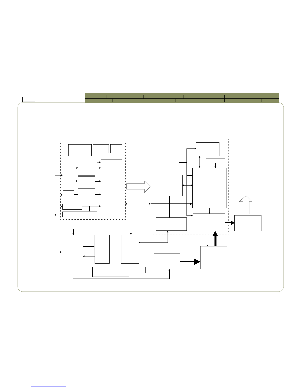
Fundamental Principle....................................................................................................... 2-1
Function Block Diagram................................................................................................................ 2-2
Optics............................................................................................................................................. 2-6
Mechanical Construction.................................................................................................... 3-1
Package Overview.......................................................................................................................... 3-2
Exploded Overview........................................................................................................................ 3-4
Recommendation Spare Parts List................................................................................................ 3-26
Procedure of Disassembly.................................................................................................. 4-1
Disassemble Lamp Module............................................................................................................ 4-3
Disassemble Top Cover and Keypad Board.................................................................................. 4-4
Disassemble Left Cover, Right Cover and I/O Bezel Module....................................................... 4-6
Disassemble Front Cover.............................................................................................................. 4-8
Disassemble Thermal Board and Main Board............................................................................... 4-10
Disassemble Ballast and Fan Module........................................................................................... 4-12
Disassemble DC-DC Board and Interlock Switch......................................................................... 4-14
Disassemble Engine, DMD and DMD Board.................................................................................. 4-15
Disassemble Color Wheel, Photo Sensor Board and Thermal Switch.......................................... 4-17
Disassemble Elevator Module....................................................................................................... 4-18
Function of Boards............................................................................................................. 5-1
DMD Board..................................................................................................................................... 5-2
Main Board..................................................................................................................................... 5-7
Keypad Board................................................................................................................................. 5-15
Thermal Board................................................................................................................................ 5-16
Table of Contents (I)

0-3 EP737 SERVICE MANUAL
Introduction Fundamental Principle Mechanical Construction Procedure of Disassembly Function of Boards Specifications
Troubleshooting Function Test and Alignment Procedure Firmware Upgrading Procedure DDC Key-In Procedure Appendix
DC-DC Board.................................................................................................................................. 5-21
Ballast............................................................................................................................................. 5-23
Specifications.................................................................................................................... 6-1
Lamp Specifications....................................................................................................................... 6-2
DMD Specifications........................................................................................................................ 6-5
DC-DC Specifications..................................................................................................................... 6-8
Lamp Driver Specifications............................................................................................................ 6-9
Troubleshooting................................................................................................................. 7-1
Equipment Needed........................................................................................................................ 7-2
Main Procedure.............................................................................................................................. 7-2
Function Test & Alignment Procedure................................................................................ 8-1
Product........................................................................................................................................... 8-2
Test Equipment.............................................................................................................................. 8-2
Test Condition............................................................................................................................... 8-2
Test Display Modes and Patterns.................................................................................................. 8-3
Inspection Procedure..................................................................................................................... 8-9
Firmware Upgrading Procedure......................................................................................... 9-1
Equipment Needed........................................................................................................................ 9-2
Setup Procedure............................................................................................................................. 9-3
Upgrading Procdure....................................................................................................................... 9-4
DDC Key-In Procedure.................................................................................................................................... 10-1
Equipment Needed........................................................................................................................ 10-2
Setup Procdure............................................................................................................................... 10-3
DDC Key-in Procedure................................................................................................................... 10-4
Appendix........................................................................................................................... 11-1
Serial Number System Definition.................................................................................................. 11-2
Table of Contents (II)

1-1 EP737 SERVICE MANUAL
Introduction Fundamental Principle Mechanical Construction Procedure of Disassembly Function of Boards Specifications
Troubleshooting Function Test and Alignment Procedure Firmware Upgrading Procedure DDC Key-In Procedure Appendix
This manual is applied to 0.7*1 DMD Color Projector with digital im-
aging functionality based on Digital Micromirror Device (DMD)
technology. Its the mode of single panel, 150 watt long life P-VIP lamp.
The manual gives you a brief description of basic technical informa-
tion to help in service and maintaining the product.
Your customers will appreciate the quick response time when you im-
mediately identify problems that occur with our products. We expect
your customers will appreciate the service that you offer them.
This manual is for technicians and people who have an electronic
background. Send the product back to the distributor for repairing
and do not attempt to do anything that is complex or is not mentioned
in the troubleshooting.
Introduction 11
11
1

1-2 EP737 SERVICE MANUAL
Introduction Fundamental Principle Mechanical Construction Procedure of Disassembly Function of Boards Specifications
Troubleshooting Function Test and Alignment Procedure Firmware Upgrading Procedure DDC Key-In Procedure Appendix
1-1 Product Highlights
- One panel 0.7 DMD XGA projection system with 1300 ANSI lumens (Marketing)
- OSRAM 150 - Watt Compact P-VIP Lamp (user replaceable)
- High efficiency cooling system with low system acoustic noise level
- Light weight Approx. 3.9 lbs.
- Manual focus projection 1 : 1.2 zoom lens
- True 1024 x 768 resolution, 16.7M True colors
- With up, down, left, and right screen reverse
- SXGA / XGA / SVGA / VGA / MAC compatibility with one M1-DA input terminal
- Auto image re-sizing to 1024 x 768 full screen
- Auto detection of computer signal input
- Auto Image synchronization (Auto-tracking / frequency / position adjustment)
- Powerful enlarge and freeze function
- Automatically saves adjustments for future use
- On-screen menu with up to 10 languages
- Built-in one speaker with 2 Watt amplifier
- Self protect timer for hot re-strike of compact P-VIP lamp
- Wireless remote control with USB mouse function and laser pointer
- Adaptive voltage control fan speed
- Noise : Expect Marketing spec - 32dB(A) (30 min)
Real Engineering spec - Max 37 dB(A) (1hr) => Same as H55.
- Build-in full screen NTSC / PAL / SECAM video capability with S-video / Composite / Component and
HDTV terminals

1-3 EP737 SERVICE MANUAL
Introduction Fundamental Principle Mechanical Construction Procedure of Disassembly Function of Boards Specifications
Troubleshooting Function Test and Alignment Procedure Firmware Upgrading Procedure DDC Key-In Procedure Appendix
1-2.1 Optical Features
sneLnoitcejorP sneLmooZlaunaMX2.1.mm5.43~8.82=f,96.2~44.2/F
eziSegamInoitcejorP )lanogaiD("3.592ot"4.32morfelbatsujdA
)"9.542~"9.63:eziSegamInoitcejorPdetsegguS(
ecnatsiDworhT )m01~5.1:ecnatsidworhtdetsegguS(m21~m4.1
)m21~m41.1-.cepSgnitekraM(
ssenthgirB
)gnitekraM(snemuLISNA0031
)egarevA(snemuLISNA0511
)muminiM(snemuLISNA0001
tsartnoC
)kcalBdnaetihWlluF(gnitekraM1:0061
)kcalBdnaetihWlluF(lacipyT1:0541
)kcalBdnaetihWlluF(muminiM1:0031
ytimrofinU
)dradnatSnapaJ(gnitekraM%58
)dradnatSnapaJ(lacipyT%57
)dradnatSnapaJ(muminiM%56
erutarepmeTroloC 0057
o
)tluafeD(K
0088ot0007
o
).xaMot.niM(K
1-2 Technical Specifications

1-4 EP737 SERVICE MANUAL
Introduction Fundamental Principle Mechanical Construction Procedure of Disassembly Function of Boards Specifications
Troubleshooting Function Test and Alignment Procedure Firmware Upgrading Procedure DDC Key-In Procedure Appendix
1-2.2 Electrical Features
ylppuSrewoP
tupniCFPhtiwzH06/05~V042-001CAlasrevinU-
PIV-PtcapmoCW051rof)etanimretedebotegattaW(-
noitarepolamron@pmaL
)tnairaverutarepmetnodnepeD(lortnocdeepsNAFecnairaV-
noitpmusnoCrewoP noitarepolamronta%01-/+ttaW091-
W53<edomybdnatS
slanimreT
)1xlanimreTelameFAD-1MASEV(tupnIretupmoC-
)1xkcajACR(tupnIoediVetisopmoC-
)1xnip-4NIDiniM(tupnIoediVS-
)1xkcajenohpmm5.3(tupnIeniloiduA-
)1xlanimretelamefnip-51buS-D(tuptuOrotinoM-
.cepslangistupnI
zHk001~51ycneuqerFcnysH-
zH021~34ycneuqerFcnysV-
)CP(BGRlangiSoediV-
mho57,p-pV7.0BGRgolanA
langis.cnyS,mho57,p-pV1BGRgolanA
.cnySV,HLTTetarapeS
.cnySlTTetisopmoC
oediV-
mho57,p-pV1oedivetisopmoC
mho57,p-pV417.0ecnanimuLoediv-S
mho57,p-pV682.0ecnanimorhC
ytilibitapmoCoediV
:sdradnatS-
,zHM34.4,)zHM85.3(M-CSTN
N,M,I,H,G,D,B-LAP
L,1K,K,G,D,B-MACES
i0801;P027;P084;i084-VTDH
oiduA
rekaepslanretni,W2,mhO-4enO-
reifilpmasttaW2-
.smrV3.0ytivitisnestupnI-

1-5 EP737 SERVICE MANUAL
Introduction Fundamental Principle Mechanical Construction Procedure of Disassembly Function of Boards Specifications
Troubleshooting Function Test and Alignment Procedure Firmware Upgrading Procedure DDC Key-In Procedure Appendix
)DxHxW(snoisnemiD
sehcni430.0-/+8.2x50.8x86.9-
)snelo/w,mm1-/+2.17x4.402x642(
sehcni430.0-/+1.3x37.8x86.9-
)snelhtiw,mm1-/+6.87x7.122x642(
thgieW .sbl9.3.xorppA
elgnAtliT msinahcemrotavelehtiweerged8
noitcerrocenotsyeK )eerged23(eerged61-/+
noitcetorProoDpmaL neporoodnehwyllacitamotuaffotuhsylppusrewoppmaL
1-2.4 Environmental Features
erutarepmeT 04~01:gnitarepO
o
C
06~02-:egarotS
o
C
ytidimuHmumixaM 04~01:gnitarepO
o
\gnisnednoc-non,).xaM(HR%08,C
06~02-:egarotS
o
gnisnednoc-non,).xaM(HR%08,C
levelesioncitsuocA
).cepsgnitekramtcepxe(ABd23
52rednU,lacipyT(ABd53
o
)C
52rednU,.xaM(ABd73
o
)C
efiLpmaL gnitekramsruoh005,1
etarlavivrus%05,lacipytsruoh002,1
edutitlA
01tf005,2~0:gnitarepO-
o
04~C
o
C
01tf000,5~005,2
o
53~C
o
C
01tf000,01~000,5
o
52~C
o
C
tf000,04:egarotS-
FBTM )leveLecnedifnoC%09(sruoh000,21nahteromgnitarepO
1-2.3 Mechanical Features

2-1 EP737 SERVICE MANUAL
Introduction Fundamental Principle Mechanical Construction Procedure of Disassembly Function of Boards Specifications
Troubleshooting Function Test and Alignment Procedure Firmware Upgrading Procedure DDC Key-In Procedure Appendix
This section provides the conceptual drawing about optics of projector.
You can realize optical projection system through the following dia-
gram and the integral part of configuration, too.
Fundamental
Principle 22
22
2

2-2 EP737 SERVICE MANUAL
Introduction Fundamental Principle Mechanical Construction Procedure of Disassembly Function of Boards Specifications
Troubleshooting Function Test and Alignment Procedure Firmware Upgrading Procedure DDC Key-In Procedure Appendix
2-1 Function Block Diagram
DVI
Port
Video
Port
IR Receiver
Remote Mouse Processor
Video
Processor
SAA7118
DVI
Receiver
SiI141
A/D
Converter
AD9883-
165MHz
Xtal=20MHz
MCLK=125MHz
DCLK=60MHz
Serial
EEPROM Flash
ROM
Image
Processor
PW166-
20RK RGB Data
Control Signal
DCLK=60MHz
DC 3.3V, 5V,
12V
CONTROL
FPGA
MICRO
CONTROLLER
SDRAM
64M
Xtal=58MHz
DMD Board
DATAPATH
FORMATTER
DPF2
0.7 XGA DDR
DMD MIRROR
MOTOR
CONTROLLER
Main Board
VESA M1
Input
Video
Input
IR
Signal
Mouse
Display
Image
PROJECTION
LENS
COLOR
WHEEL
RGB Light Source
Light
Source
DC
to
DC
BALLAST
150W LAMP
Thermal
Board
Interlock
Switch
Thermal
Sensor*2 Fan*4
Normal=AC 85V Lamp turning on=20KV
12V to
Lamp
Driver
Control
Signal
DC
3.3V,
5V,
12V
LampLit
Lamp Enable
DC 3.3V, 5V, 12V
Control Signal
DC
400V
Power
AC
110V ~
220V

2-3 EP737 SERVICE MANUAL
Introduction Fundamental Principle Mechanical Construction Procedure of Disassembly Function of Boards Specifications
Troubleshooting Function Test and Alignment Procedure Firmware Upgrading Procedure DDC Key-In Procedure Appendix
2-1.1 Main Board Block Diagram
Image
Processor
ACTDATA
DRE [0..7]
DGE [0..7]
DBE [0..7]
DCLKOZ
YSYNCOZ
HSYNCOZ
Pixel Work 166
DMD
BOARD
Microprocessor
PW166
RESET
CIRCUIT
THERMAL
BOARD
KEYPAD
FLASH ROM
TE28F800
USB
Controller
cy7c63612
IR Receiver
TO PC
AMP
LT1399
AD9883
A / D
Multiplexer
74LVC157
SiI141
Digital
Receiver
Video
Dicoder
SAA7118
Multiplexer
74LVC157
EPROM
24LC21A
Audio
Amplifier
LM4832
Audio
Amplifier
LM1877
RS-232
Transceiver
MAX202
CLOCK
Generator
ICS 501/502
RESETZ
LAMPLITZ IR SYNC
IR-F
IR-R
USB_D+
USB_D-
PWBT
ERR_OUT
SHUTDW#
RESET
7SEC
STANDBY
VPPEN
A [18:1]
D [0:15]
ROMOEn
ROMWEn
BOOTWE
Keypad
Control
SYNC
PW_LED
LED 1
LED 2
MCLK
DCLK
IRDATA 1
IRDATA 2
Analog
Input
<Analog> D-Sub Output
GBLKSPL
GRE [0..7]
GGE [0..7]
GBE [0..7]
AGFBK
AUSOUT
GHS
GUS
GPEN
GFBk
DHSOUT. DVSOUT. DFPGPEN.
DHSOUT. DFP/VGA# GRE [0..7]
GGE [0..7]
GBE [0..7]
Vy [0..7]
VUV [0..7]
VCLK
VPEN
VVS
VHS
VFIELD
Video Input
RXD
TXD
SDA
SCL
Audio Input
IR-R
IR-ONOFF
AGCOAST
ASOGOUT
Speaker
SDA 1
SCL 1
TO PC

2-4 EP737 SERVICE MANUAL
Introduction Fundamental Principle Mechanical Construction Procedure of Disassembly Function of Boards Specifications
Troubleshooting Function Test and Alignment Procedure Firmware Upgrading Procedure DDC Key-In Procedure Appendix
2-1.2 DMD Board Block Diagram
CUSTOMER FRONT END
VSYNCZ
HSYNCZ
ACTDATA
OLACT
RV(7:0), GY(7:0), BU(7:0)
SYNCVAL
IIC BUS
LAMP CONTROL & STATUS
UNIV. SERIAL BUS
COLOR WHEEL INDEX
PIXEL CLOCK
DATAPATH
FORMATTER
DDP1000
RAMBUSTM
CLOCK
GEN
CLOCK OSC.
OR CRYSTAL
RDRAM
Short
Channel
CONFIG/SEQUENCE
MICRO. CODE
FLASH
ALLERGO
MOTOR
CONTROLLER
ADDRESS(18)
0.7 DDR DMD
1024*768
MRSTZ
MOTOR CONTROL
DMD CONTROL
DMD DATA (63:0)
DMDCLLK
CONTROL
SR16 CONTROL
MOTOR
DRIVE
MOTOR STATUS
DATA (16)
VCC2, VOFFSET,
VBIAS, VRESET
GENERATION
VOFFSET/VCC2
VRESET
VBIAS
MBIASRST(16)
+ 12V
+ 5V
RESET
ASIC

2-5 EP737 SERVICE MANUAL
Introduction Fundamental Principle Mechanical Construction Procedure of Disassembly Function of Boards Specifications
Troubleshooting Function Test and Alignment Procedure Firmware Upgrading Procedure DDC Key-In Procedure Appendix
2-1.3 Thermal Board Block Diagram
THERMAL BOARD Interface +12V*1
+5V*2
+3.3V*2
GND
LAMPEN (RESETZ)
CWINDEX
LAMPLIT
Power on/off (only 5V, 15V)
3P Connector
3P Connector*4
2P Connector
4P Connector*2
14P Connector
PHOTO
SENSOR
FAN1-4
THERMAL
SWITCH
THERMAL
SENSOR
DC TO DC POWER SUPPLY
+15VSBY
+5VSBY
+3.3VSBY
LAMPLIT_IN 30P Connector
to Formatter
Board
LAMPEN_OUT
3P Connector
IR
SENSOR

2-6 EP737 SERVICE MANUAL
Introduction Fundamental Principle Mechanical Construction Procedure of Disassembly Function of Boards Specifications
Troubleshooting Function Test and Alignment Procedure Firmware Upgrading Procedure DDC Key-In Procedure Appendix
2-2 Optics
2-2.1 Conceptual Drawing
1. 150W P-VIP Lamp 5. Mirror 2
2. Color Wheel 6. Mirror 1
3. Hollow Rod 7. Relay Lens
4. Condenser Lens 8. DMD Module
1
2
3
6
5
4
7
8

2-7 EP737 SERVICE MANUAL
Introduction Fundamental Principle Mechanical Construction Procedure of Disassembly Function of Boards Specifications
Troubleshooting Function Test and Alignment Procedure Firmware Upgrading Procedure DDC Key-In Procedure Appendix
2-2.2 Basic Functions
150W P-VIP Lamp The light source.
Color Wheel Separating the light beam into and produce R.G.B colors.
Hollow Rod Making the light beam uniform.
Condenser Lens Condensing the light beam.
Mirror Folding optical path.
DMD Module Displaying component.

3-1 EP737 SERVICE MANUAL
Introduction Fundamental Principle Mechanical Construction Procedure of Disassembly Function of Boards Specifications
Troubleshooting Function Test and Alignment Procedure Firmware pgrading Procedure DDC Key-In Procedure Appendix
This section provides the package and exploded overview, replaceable
parts list and recommendatiom parts list for the portable projector.
You can place an order for correct parts in the recommendation parts
list.
Mechanical
Construction 33
33
3

3-2 EP737 SERVICE MANUAL
Introduction Fundamental Principle Mechanical Construction Procedure of Disassembly Function of Boards Specifications
Troubleshooting Function Test and Alignment Procedure Firmware pgrading Procedure DDC Key-In Procedure Appendix
3-1 Package Overview
Replacement Parts List
metIN/P.veRnoitpircseD
100.10368.KA A 737PEROFELUDOMXOBAZZIP
1200.21000.63B SEIRESPPLROFSU,DRACTNARRAW
2100.81000.63A ROFASU,MROFNOITARTSIER;YTNARRAWDEDNETXE
SEIRESPPL
3100.10368.63A 737PELAUNILITLUMDRACTRATSKCIUQ
4100.10368.24A 737PEmm0081NIP3NIDINIMOT)EULB(232-SRELBAC
5110.01105.24A 13BXM8.1ACRELBAC
6130.90205.24A 13BXM8.1OEDIV-SELBAC
7100.40858.24A XELOMM8.1)A(BSU/AVOTA-1MELBAC
8100.11858.24A 13BXKCALBM8.1KCAJINIMOTKCAJINIMLEBAC
9100.20368.63A 737PEROFEDIUS'RESU
01100.10308.64B V5.14#YRETTAB
11100.20338.55A 037orPzEXOBYROSSECCANOTRAC
21100.10368.65A 737PEEPEXOBYROSSECCAROFNOITITRAP
31100.34438.07A AMOTPO(537orPzERELLORTNNOCETOMERYROSSECCA
)LEBAL

3-3 EP737 SERVICE MANUAL
Introduction Fundamental Principle Mechanical Construction Procedure of Disassembly Function of Boards Specifications
Troubleshooting Function Test and Alignment Procedure Firmware pgrading Procedure DDC Key-In Procedure Appendix
Replacement Parts List
metIN/P.veRnoitpircseD
100.30368.PS A 737PEELBACDNAROTCENNOCTNUOMNILIEC
1190.20325.53A KNALB29*801NOTRACLEBAL
2100.30368.63A 737PELAUNAMTNUOMNILIEC
3100.12125.15A 0205-TML40.0*07*0013#REPPIZABEP
4100.52708.15A EPYTUMC05*02*02ABEP
5100.60708.55A TNUOMNILIECROFMC84*02*02BANOTRAC
6100.30368.65A 737PEEPETNUOMNILIECROFMOTTOBNOIHSUC
7100.90858.65A 13BXEPETNUOMNILIECROFPOTNOIHSUC
8100.62708.16A ERUTCURTSHCNI61/5TUN/WERCS
9100.70368.57A 737PEELUDOMTNUOMNILIECYSSA
01060.325A1.58A KOLYNiN6*3MHCEMNAPWERCS
11120.90205.24A 006orPzEM5SHV-SELBAC
21100.50368.24A 737PEXELOMM5)A(BSU/AVOTA-1MELBAC
31110.51708.24A M5ACROTKCAJINIMELBAC

3-4 EP737 SERVICE MANUAL
Introduction Fundamental Principle Mechanical Construction Procedure of Disassembly Function of Boards Specifications
Troubleshooting Function Test and Alignment Procedure Firmware pgrading Procedure DDC Key-In Procedure Appendix
3-2 Exploded Overview

3-5 EP737 SERVICE MANUAL
Introduction Fundamental Principle Mechanical Construction Procedure of Disassembly Function of Boards Specifications
Troubleshooting Function Test and Alignment Procedure Firmware pgrading Procedure DDC Key-In Procedure Appendix
Replacement Parts List
metIN/P.veRnoitpircseD
100.10368.CD A 737PE.C.D
1200.20858.24A 13BXTSALLAB/DB-LAMREHT1601LUmm0562#41.A.W
2100.30858.24A 13BXTSALLAB/CD-CDmm58122#P4.A.W
3100.90858.24A DBLAMREHT/TSALLABmm52182#P3.A.W
4100.17000.15A 13BX6-FCM-PTROPPUSRECAPS
5100.10368.15A 737PEX003NLYRONREVOCMOTTOBPMAL
6200.81000.16A B5.3-5.8*3MHCEMNAPWERCSKCOL
7100.20368.16A 737PE2505LATEKCARBEDIUNAF
8100.40368.16A 737PELAOOLAMOTPO
9100.10368.07A 737PEELUDOMREVOCPOTYSSA
01100.20368.07A 737PEELUDOMREVOCMOTTOBYSSA
11100.30368.07A 737PEELUDOMREVOCTNORFYSSA
21100.50368.07A 737PEELUDOMREVOCTHIRYSSA
31100.60368.07A 737PEELUDOMREVOCTFELYSSA
41100.70368.07A 737PEELUDOMENINEYSSA
51100.20368.57A 737PETNORFNIRSUCOFYSSAYUB
61100.20368.08E 737PEDRAOBLAMREHTABCP
71050.626A1.58A KOLYNKCALB5*6.2MHCEMNAPWERCS
81060.326A1.58A 0063XVKOLYN6*3MNAPENIHCAMWERCS
91100.51368.07A 737PEELUDOMDRAOBNIAMABCPYSSA
02100.80368.07A 737PEELUDOMPMALYSSA
12100.90368.07A 737PEELUDOM51-05NAF
22100.81368.07A 737PEELUDOMCINOSANAPF3LAFNAF
metIN/P.veRnoitpircseD
32100.01858.07A 13BXELUDOMCD_CD
42140.52000.58A SSARB0.4L*6.6H*5.2MO/IXEH
52100.90368.25A 737PEREBBURMOTTOBDRAOBNIAM
62100.71368.16A 737PE403SUSPAPMALROFEKARBEFAS
72040.525A1.58A KLNiN4*5.2MHCEMNAPWERCS
Other manuals for EP737
4
Table of contents
Other Optoma Projector manuals

Optoma
Optoma UHD51A User manual

Optoma
Optoma EP759 User manual

Optoma
Optoma EP719R User manual

Optoma
Optoma DV20 User manual

Optoma
Optoma HD83 User manual

Optoma
Optoma HD20 User manual

Optoma
Optoma GT1080e User manual

Optoma
Optoma TW675UST-3D User manual

Optoma
Optoma EX520 User manual

Optoma
Optoma W304M User manual

Optoma
Optoma EH503 User manual

Optoma
Optoma ZU500TST User manual

Optoma
Optoma Optoma EP730 User manual

Optoma
Optoma EP763 User manual

Optoma
Optoma EzPro710 User manual

Optoma
Optoma PRO360W User manual

Optoma
Optoma EW695UT User manual

Optoma
Optoma TX776 Technical manual

Optoma
Optoma TX-330 Installation and operation manual

Optoma
Optoma TW330 User manual