Optoma HD2+ DC3 User manual

奇菱光電股份有限公司 Chi Lin Optronics Corp.
Doc. No CS-72601
Version A3
Title
CHT-726 Level 1 Service Manual
Page
1 / 75
Service Manual
For
HD2+ DC3 DLP Front Projector
Copyright©2004 Chilin Optronics Corp. All rights reserved.

奇菱光電股份有限公司 Chi Lin Optronics Corp.
Doc. No CS-72601
Version A3
Title
CHT-726 Level 1 Service Manual
Page
2 / 75

奇菱光電股份有限公司 Chi Lin Optronics Corp.
Doc. No CS-72601
Version A3
Title
CHT-726 Level 1 Service Manual
Page
3 / 75
Service Safety Notes
Please read the Service Safety Notes before any service work is performed. Service work should be
performed by qualified service technicians who are familiar with safety check and the DLP front
projector, and take related service training before servicing.
Warning
1. Place the projector on even surface during service work is performed.
2. Service work need to perform in an environment that is smoke and dust free. When used in areas
where there is a lot of smoke or dust, the filter and lens should be cleaned before projector is returned
to the user.
3. Disconnect power cord before servicing
4. The temperature of the lamp, ventilation slots and objects next to them may be extremely high during
operation. Do not touch these areas before the temperature is sufficiently cool down.
5. Do not touch the internal structure of the lamp, any stain on the internal structure may cause
unfixable damage on the lamp.
6. Do not stare into the beam of light or view directly. If stare into the beam of light is necessary for
checking the lens, please wear sun-glasses.

奇菱光電股份有限公司 Chi Lin Optronics Corp.
Doc. No CS-72601
Version A3
Title
CHT-726 Level 1 Service Manual
Page
4 / 75
Contents
1. Purpose..........................................................................................................................5
2. Definition of service level.............................................................................................5
3. Specification..................................................................................................................5
4. Structure of the Product..............................................................................................6
4.1 I/O Interface ........................................................................................................... 6
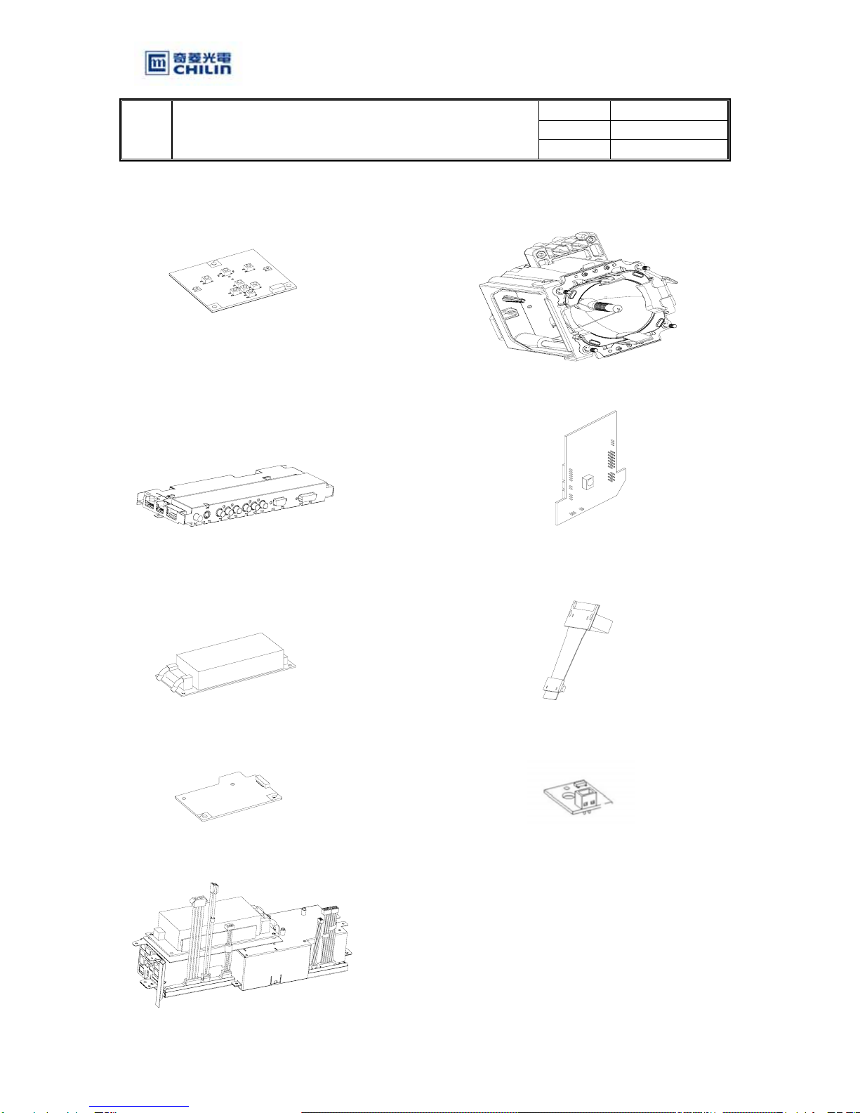
4.2 Exploded View (attached as Appendix II) ............................................................. 7
4.3 Detail description of parts shown in 4.2 Product exploded View.......................... 8
4.4 Composition of Level 1 Modules (Parts)............................................................... 9
5. Troubleshooting .........................................................................................................11
5.1 Troubleshooting Table ………………………………………………………….11
5.2 Block Diagram ………………………………………………………………….14
6. Service Mode...............................................................................................................15
6.1 Options: ................................................................................................................ 15
6.2.1 Video Formatter ........................................................................................... 15
6.2.2 DLP Vsync ................................................................................................... 15
6.2 Test Patterns:........................................................................................................ 16
6.2.1 DLP Test Patterns ........................................................................................ 16
6.2.2 Lens Checkerboard....................................................................................... 21
6.2.3 4 X 4 Checkerboard ..................................................................................... 21
6.2.4 Scaler Test Patterns ...................................................................................... 22
6.3 Adjust CW............................................................................................................ 23
6.4 CW Index ............................................................................................................. 23
6.5 VGA Auto Calibration ......................................................................................... 24
6.6 MST 9888 Comp YPbPr ...................................................................................... 24
6.7 AD9882 VGA RGB ............................................................................................. 24
6.8 SAA 7118............................................................................................................. 25
6.9 DLP RGB Gain Offset ......................................................................................... 25
7. Firmware Updade ......................................................................................................26
8. Replacement Procedure (Disassembly & Assembly)..............................................28
8.1 Replace The Lamp module .................................................................................. 28
8.1.1 Resetting Lamp Timer.................................................................................. 29
8.2 Replace Cooling Fans .......................................................................................... 31
8.2.1 Replace The Front Axial Fan ....................................................................... 33
8.2.2 Replace The Rear Axial Fan ........................................................................ 36
8.2.3 Replace The Blower Fan.............................................................................. 39
8.3 Replace The Keypad ............................................................................................ 48
8.4 Replace The Control Board.................................................................................. 51
8.5 Replace The Connection Board ........................................................................... 54
8.6 Replace The Video Module, The I/O Board, The Ballast, The Thermal Sensor,
and The Power Module ........................................................................................................ 57
8.7 Procedures for the video module adjustment....................................................... 71
Appendix I : Spare Parts List for CHT 726..........................................................................75

奇菱光電股份有限公司 Chi Lin Optronics Corp.
Doc. No CS-72601
Version A3
Title
CHT-726 Level 1 Service Manual
Page
5 / 75
1. Purpose
The purpose of this manual is for the reference of authorized technician while proceeding level 1
service for the product mentioned in this manual.
2. Definition of service level
Considering the service capability and the equipments of each service station may be different and the
raising on service efficiency, service works have been concluded to 3 levels and defined by Customer
Service Dept. (CS hereafter).
The definition of “level 1 service” is defined based on service efficiency and effectiveness
considerations. Level 1 service means modules replacement for projector. The concrete composition of
level 1 modules (parts) will be mentioned in item 4.4 Composition of level 1 modules (parts). Level 1
service can be perform in a smoke and dust free environment and with limited equipments like
computer and DVD Player.
“Level 2 service” is defined as service on the PCBA. The technician who performs “level 2 service”
should be knowledgeable on electricity system, except safety checks. Electronic equipment, such as
AC/DC power source, oscilloscope, and other test equipments, are needed for performing level 2
service.
“Level 3 service” is defined as service on the optical engine, but fans and lamp replacement. The
service work on the optical engine should be performed in clear room.
3. Specification
Please refer to CLO released HD2+ DC3 DLP Front Projector Approval Sheet.

奇菱光電股份有限公司 Chi Lin Optronics Corp.
Doc. No CS-72601
Version A3
Title
CHT-726 Level 1 Service Manual
Page
6 / 75
4. Structure of the Product
4.1 I/O Interface
+
Input 3
Video/S-Video
Input 1
Component 1
Input 2
Component 2
Rear IR Sensor AC SocketRS232 Terminal
Input 4
DVI/ PC

奇菱光電股份有限公司 Chi Lin Optronics Corp.
Doc. No CS-72601
Version A3
Title
CHT-726 Level 1 Service Manual
Page
7 / 75
4.2 Exploded View (attached asAppendix II)
2-1
2
2
2-4
2
6
2-5
2
2-3
2
2
2-7
2
39
2
40
4-5
4
29
2
4-4
2
15
8
10
2
2-2
2
30
2
2
20
6-2
4
1
28 34
438
37
2
6-5
36
2
6-6
4
6-3
1
2-6 31
8
3
6-8
4
28
4
21
1-9
2-8
9
22
33
2
5-1
4
5-4
26
6-7
29
1
6-9
4
6-1
6-4
4
27
25
2
29
13
7
24
1-1
31
5
12
32
1
19
14
16
11
18
32
2
32
1
2
2
2
3-1
3-2
35
1
1
5-5

奇菱光電股份有限公司 Chi Lin Optronics Corp.
Doc. No CS-72601
Version A3
Title
CHT-726 Level 1 Service Manual
Page
8 / 75
4.3 Detail description of parts shown in 4.2 Product exploded View
ITEM PART NAME QTY ITEM PART NAME QTY
1 P07260 TOP COVER SET(SILVER) 1 30-12 SCREW PH M3-0.5*5 C2 3
2 P05760 BOTTOM COVER(SILVER) 1 30-13 SCREW PH+EXW M4-0.7*6 C2 1
3 P05760 LAMP DOOR(SILVER) 1 30-14 SCREW PH M3-0.5*5 C2 13
4 P05760 FRONT LEG BUTTON 2 30-15 WIRE POWER-BALLAST 3P 150MM 1
5 P05760 FRONT LEG 2 30-16 WIRE FORMAT-BALLAST 5P 280MM 1
6 P05760 FRONT LEG COVER 2 31 PCBA P05760 CONTROL BOARD 1
7 P05760 FRONT LEG TOP HOUSING 2 32 PCBA P05760 KEYPAD BOARD 1
8 P05760 8025 FAN LOWER DUCT 1 33 PCBA P05760 VIDEO BOARD 1
9 P05760 8025 FAN UPPER DUCT 1 34 PCBA P05760 CONNECTION BOARD 1
10 P05760 8025 LAMP FAN RUBBER 4 35 WIRE POWER-CONTROL 6P 220MM 1
11 P05760 REAR RUBBER FOOT 1 36 WIRE POWER-VIDEOFORMAT 20P 120 1
12 P05760 FRONT LEG RUBBER 2 37 WIRE POWER-LAMPSWITCH 4P 90MM 1
13 P05760 KEYPAD PCB MYLAR 1 38 WIRE VIDEO-I/O 10P 60MM 1
14 P07260 RING CAP MYLAR RIGHT 1 39 WIRE VIDEO-CONTROL 12P 250MM 1
15 P07260 RING CAP MYLAR LEFT 1 40 WIRE CONTROL-KEYPAD 6P 430MM 1
16 FAN 12V DC 0.09A D80 AXIAL 1 41 WIRE VIDEO-KEYPAD 14P 240MM 1
17 FAN 12V DC 0.09A D80 AXIAL 1 42 WIRE SENSOR(P)-CONTROL 2P 240 1
18 P05760 VIDEO UPPER SHIELDING 1 43 WIRE POWER-THERMOSTAT 2P 220MM 1
19 P05760 BOTTOM NET 1 44 WASHER D2.5 E-RING STEEL 2
20 P05760 BOTTOM NET COVER 1 45 SCREW PH M3-0.5*5 C2 9
21 P05760 VIDEO SIDE NET 1 46 SCREW PH D3*8 C2 15
22 P05760 PCB FAN METAL DUCT 1 47 SCREW PH D3*5 C2 4
23 P05760 PCB FAN DUCT SHIELDING 1 48 SCREW BH M3-0.5*8 C2 13
24 P05760 LAMPDOOR FRONT LOCK 1 49 SCREW WH8 D3*6 C2 5
25 P05760 LAMPDOOR SIDE LOCK 1 50 SCREW WH8 M3-0.5*4 C2 10
26 P05760 FRONT LEG SLIDING 2 51 SCREW FH M3-0.5*10 C2 2
27 P05760 SAFETY LABEL 1 52 SCREW FHM3*8TP-P 4
28 P05760 I/O DECORATION LABEL 1 53 SCREW BH M4-0.7*9 C2 (E-RING) 2
29 P07260 OPTICAL ENGINE 1 54 SCREW HH UNC#4-40*8 H5 4
30 P05760 POWER MODULE 1 55 SCREW HH UNC4#-40*7 H5 2
30-1 P05760 POWER LOWER SHIELDING 1 56 P05760 FRONT LEG SPRING 2
30-2 P05760 POWER UPPER SHIELDING 1 57 P05760 CABLE CLAMP 1
30-3 P05760 BALLAST SHIELDING 1 58 AL TINESL 100*37 (2-D6) 1
30-4 P05760 I/O PCB SHIELDING 1 59 P05760 EMI GASKET 1
30-5 P05760 POWER LOWER MYLAR 1 60 TEMPERATURE LABEL 1
30-6 P05760 POWER UPPER MYLAR 1 61 P05760 DLP LOGO LABEL 1
30-7 P05760 BALLAST LOWER MYLAR 1 62 P07200 LOGO LABEL METAVISION 1
30-8 P05760 BALLAST 250W AC380V 1 63 P05760 TOP COVER SPONGE 2
30-9 PCBA P05760 IO BOARD 1 64 P05760 CONNECTION PRESSING 1
30-10 PCBA P05760 SENSOR BOARD 1 65 P05760 COVER LENSSHIFT SPONGE 1
30-11 PCBA P05760 POWER BOARD 1

奇菱光電股份有限公司 Chi Lin Optronics Corp.
Doc. No CS-72601
Version A3
Title
CHT-726 Level 1 Service Manual
Page
9 / 75
4.4 Composition of Level 1 Modules (Parts)
Level 1 service means to replace all mechanical parts (cover, base, screw and label so on),electronic
modules (also include the cable which connects two modules) listed below on this page and next
page.
In order to help technician understand the figure and composition of each module and mechanical
part, drawing of modules and parts are as drawing listed on this page and next page. Others (ex.
Cable, Screw, Packing material, Accessories, etc.) are not included in following drawings. The items
of level 1 service will be updated base on ASP (After Service Provider) capability and
efficiency/effectiveness consideration.
Mechanical Parts:
Upper Cabinet Lamp Door
Blower Fan
Rear Axial Fan Bottom Cabinet
Front Axial Fan

奇菱光電股份有限公司 Chi Lin Optronics Corp.
Doc. No CS-72601
Version A3
Title
CHT-726 Level 1 Service Manual
Page
10 / 75
Electronic Parts:
Keypad
Lamp
Video Module
Control Board
Ballast Connection Board
IO Board Thermal Sensor
Power Module

奇菱光電股份有限公司 Chi Lin Optronics Corp.
Doc. No CS-72601
Version A3
Title
CHT-726 Level 1 Service Manual
Page
11 / 75
5. Troubleshooting
You use the Troubleshooting section to diagnose problems with projector. You can refer to a
variety of symptoms for troubleshooting. Each symptom leads you trough a series of steps that
will ultimately result in a solution. The solutions begin with the most simple and progress to the
most complex.
In addition to the Troubleshooting Table, you can also check internal voltages and signals to
diagnose a defective part by Block Diagram.
5.1 Troubleshooting Table
Symptoms Possible Cause Countermeasures
Blue LED doesn’t light up The cable from the keypad to
control board does not connect
well.
The cable from control board to
power module doesn’t connect
well
The keypad malfunction
The control board defective
The power module malfunction
Check the connection of the cables
If the projector illuminates after
pressing the power key, please replace
the keypad.
Replace the control board.
Replace the failed power module
Remote controller failure Batteries are dead
Remote controller malfunction
IR sensor is malfunction
Replace the batteries
Replace the remote controller
If the remote works fine, then test the
front and rear IR sensors, if the front
IR sensor fails, replace the control
board. If the rear IR sensor
malfunctions, replace the RS232
board.
The blue LED and the over
temperature indicator flash
alternately
The cable for the front/rear
thermal sensor doesn’t connect
well.
The front/rear thermal sensors
malfunctions
Reconnect the cable to connector.
Replace the abnormal front/rear
thermal sensor
The sequence is two blue
LED blink followed by one
red indicator blink
The wire for fan doesn’t connect
well
The rear Axial Fan failure
The front Axial Fan failure
The blower fan failure
Reconnect the wire to connector
Replace the malfunction fan
(front/rear/blower fan).
All three fans do not rotate. The control board fails
Wrong firmware for the control
board.
Replace the control board.
Please contact CLO for the firmware
update on the control board.
Color wheel does not spin
after the projector power on
The wire from the power module
to the formatter board does not
connect well
The 4 Pin FFC doesn’t well
connect the color wheel and the
Check the wire
Check the connector pins on connect
board.
Remove the connect board from the
video module and disconnect the wire

奇菱光電股份有限公司 Chi Lin Optronics Corp.
Doc. No CS-72601
Version A3
Title
CHT-726 Level 1 Service Manual
Page
12 / 75
formatter board
The connect board deficient
The video module malfunctions
The formatter board fails.
from the power module to Video
module, power on projector, if the
color wheel spin normally, it means
the formatter board functions well, but
the video module malfunctions.
Otherwise, the formatter board fails,
please contact CLO for level 3
service.
The lamp doesn’t light up
after the projector powers
on, but the color wheel and
fans spin normally
Lamp failure
The 5-pin wire which connects
from ballast to the formatter board
doesn’t connect well
The black wire from Ballast to
lamp doesn’t connect well or is
failed
The white switch from the power
module to the lamp housing
doesn’t well connect.
The connect board malfunctions
or doesn’t connect the formatter
board and the video module well
The Ballast malfunctions
The rotation rate of the color
wheel isn’t correct.
Replace the lamp
Reconnect the wires or replace the
failed wires
Reconnect the connect board. If it is
failed, replace it.
Replace the ballast
The failure on photo sensor will cause
the spin rate of color wheel isn’t
correct, please contact CLO for the
level 3 service for repairing photo
sensor.
The keypad malfunction Keypad is defective if one or two
buttons no function
The wire from the video module
to the keypad doesn’t well
connect.
The video module malfunctions if
all buttons no function
Replace the keypad if one or two
buttons no function
Reconnect the wire
Replace the video module if all
buttons no function.
Projector turns off
automatically in minutes
after power on.
The control board malfunctions Replace the failed control board.
Screen flickering The lamp failure
The Ballast failure
Replace failed lamp
Replace the ballast with a good one.
Screen jagged The de-interlace malfunctions
Replace the video module
Incorrect image’s color Incorrect color wheel index
Wrong firmware for the formatter
board
Feed in Red 256 gray bar pattern and
adjust the color wheel index
Reload firmware. Please contact CLO
for the detail.
“Power Off” message
keeps showing up
automatically.
The control board fails
Replace the control board

奇菱光電股份有限公司 Chi Lin Optronics Corp.
Doc. No CS-72601
Version A3
Title
CHT-726 Level 1 Service Manual
Page
13 / 75
White verticals on the
image
The connect board malfunction
DMD malfunctions
Replace connect board
Contact CLO for level 3 service
Incorrect image The connect board does not
connect well
The video module is defective.
The connector on the video
module fails
Wrong firmware on the formatter
board
DMD failure
Reconnect the connect board
Replace the connect board.
Replace the video module
Reload correct firmware to formatter
board. Please contact CLO for the
detail
Contact CLO for level 3 service
1/16 of image area is
shown as a horizontal stripe
The formatter board malfunction Contact CLO for level 3 service.
Update firmware failure The cable between the Video
module and the power module
doesn’t well connect or fail
The cable from the video module
doesn’t connect to the RS232
board
The RS232 input fails
The video module failure
Check the connection between the
video module and the power module.
If it is failed, replace it.
Check the cable which connects the
video module and the RS232 board.
Replace the RS232 board
Replace the video module.

奇菱光電股份有限公司 Chi Lin Optronics Corp.
Doc. No CS-72601
Version A3
Title
CHT-726 Level 1 Service Manual
Page
14 / 75
5.2 Block Diagram

奇菱光電股份有限公司 Chi Lin Optronics Corp.
Doc. No CS-72601
Version A3
Title
CHT-726 Level 1 Service Manual
Page
15 / 75
6. Service Mode
The Service Mode is released for authorized distributor and technician only. It provides Test Patterns,
Adjust CW, CW Index, VGA Auto Calibration, MST9888 Component YPbPr, AD9882 VGA RGB,
SAA7118, DLP RGB Gain Offset, and firmware version information for the Video board, the formatter
board, and the control board.
Authorized technician will need to enter service mode when doing inspection and color setting
adjustment after replacing the video module.
How to enter Service Mode
By pressing clockwise and “MENU” button to enter into the main menu of the
Service Mode.
How to exit Service Mode
Press the “ exit” button to leave Service Mode
6.1 Options:
There are two items under Option, one is video format, which is set to “Auto” generally, and another is
DLP Vsync.
6.2.1 Video Format
Video Format provides 20 different formats, such as NTSC 60Hz, PAL 50/ 60Hz…etc. for use.
Normally, the default of video format is “Auto”, so that projector to take all video formats. However,
distributor would force projector to take one video format if needed.
※ Caution: Once the Video Format is selected to particular format, projector will not read signal of
other format.
6.2.2 DLP Vsync
DLP Vsync shows the signal is 50Hz or 60Hz.

奇菱光電股份有限公司 Chi Lin Optronics Corp.
Doc. No CS-72601
Version A3
Title
CHT-726 Level 1 Service Manual
Page
16 / 75
6.2 Test Patterns:
Test Patterns provides several patterns for checking the DMD chip, back focal length, ANSI contrast,
and scaler.
6.2.1 DLP Test Patterns
DLP Test Patterns contains 10 test patterns in order to check blemish, dark pixel, bright pixel, unstable
pixel, adjacent pixels, and border defects.
Blue test screen
This pattern is used to test for Major Dark Blemishes and Dark Pixels. All areas of the screen are
colored at a specific blue level, based on a standard 0-255 RGB scale:
Major Dark Blemish
Test
Blue Value 90
Red Value 0
Green Value 0
Gray 30 test screen
This pattern is used to test light border blemishes and bright pixels. All areas of the active area are
colored at a specific gray level, based on MS Paint 0-255 RGB scale:
Border Defect Test
Blue Value 30
Red Value 30
Green Value 30
Gray 10 test screen
This pattern is used to test Major Light Blemishes and Light Pixels. The full screen area is colored at a

奇菱光電股份有限公司 Chi Lin Optronics Corp.
Doc. No CS-72601
Version A3
Title
CHT-726 Level 1 Service Manual
Page
17 / 75
specific gray level, based on a standard 0-255 RGB scale:
Major Light Blemish
Test
Blue Value 10
Red Value 10
Green Value 10
White test screen
This pattern is used to test Minor Dark Blemishes. The full screen area is colored specifically, based on
a standard 0-255 RGB scale:
Minor Dark Blemish
Test
Blue Value 255
Red Value 255
Green Value 255
Black test screen
This pattern is used to test Minor Light Blemishes. The full screen area is colored specifically, based
on a standard 0-255 RGB scale:
Minor Light Blemish
Test
Blue Value 0
Red Value 0
Green Value 0
Red ramp test screen
This pattern is used to test for unstable pixels. The full screen area is colored at an increasing red level
on a standard 0-255 RGB scale, beginning at 0 (black), and ending at 255 (full red):
Unstable Pixel Test
Blue Value 0
Red Value Start 0, end 255
Green Value 0

奇菱光電股份有限公司 Chi Lin Optronics Corp.
Doc. No CS-72601
Version A3
Title
CHT-726 Level 1 Service Manual
Page
18 / 75
H/V Grid test screen
This pattern is used to test projection lens performance. It is CLO internal checking pattern for
production. It is nothing to go with DMD Checking.
H/V Grid test screen
Blue Value N/A
Red Value N/A
Green Value N/A
Red gray scale test screen
This pattern is used to test projection lens performance. It is CLO internal checking
pattern for production. It is nothing to go with DMD Checking.
Red gray scale test screen
Blue Value 0
Red Value Start R0-G0-B0,
End R255-G0-B0
Green Value 0
Green gray scale test screen
This pattern is used to test projection lens performance. It is CLO internal checking
pattern for production. It is nothing to go with DMD Checking.
Green gray scale test screen
Blue Value 0
Red Value 0
Green Value Start R0-G0-B0,
End R0-G255-B0
Blue gray scale test screen
This pattern is used to test projection lens performance. It is CLO internal checking
pattern for production. It is nothing to go with DMD Checking.

奇菱光電股份有限公司 Chi Lin Optronics Corp.
Doc. No CS-72601
Version A3
Title
CHT-726 Level 1 Service Manual
Page
19 / 75
Blue gray scale test screen
Blue Value Start R0-G0-B0,
End R0-G0-B255
Red Value 0
Green Value 0
ACCEPTANCE REQUIREMENTS
1. Conditions of Acceptance All DMD image quality returns will be evaluated using the following
projected image test conditions:
a. Texas Instruments performs image quality acceptance testing on specifically designed
HD2 DMD test equipment. If the DMD is judged to complete this test successfully, it is
acceptable.
b. Texas Instruments understands the customer will perform image quality testing in their
own PTV application. Incoming test conditions must be mutually agreed to between
customer and Texas Instruments before initial DMD acceptance testing begins.
c. Texas Instruments recommends cleaning the DMD before installation to the projector,
according to the instructions in the DMD Cleaning Document (TI drawing #2504640).
d. Texas Instruments recommends handling the DMD according to the instructions in the
DMD Handling Document (TI drawing #2504641)
e. Projector de-gamma correction Curve shall be in accordance with Test Screen definitions
on sheets 3 & 4 of this document. The correct RGB value must align with the
appropriate De-Gamma Curve.
Reference Note # 1:
If the De-Gamma curve is not known then the Linear Lux values for a given test screen
can be calculated by the following equations The following are center point Lux
measurements for a gray screen calculation. SLR (Spoke Light Recapture) is a
contributor to the white Lux value. For absolute accuracy it must be turned off when
making the White Lux measurement.
( White Lux value – Black Lux value)
--------------------------------------------------- = Lux per Step
255
Therefore, the Lux Value of a Gray 10 = 10 x Calculated Lux per Step
Reference Note # 2:
Peak Lux Percent is calculed by determining what precent of 255 is a test screen.
Example: Gray 10 is 10 / 255 or 3.9% of the white test screen’s Lux value.
f. The diagonal size of the projected image shall be at minimum 52inches (132cm).
g. The projected image shall be inspected from a 60 inch (152cm) minimum viewing
distance.
h. Projector must be properly focused on the DMD array as shown on the screen.
i. Testing time is limited to 20 seconds per screen.

奇菱光電股份有限公司 Chi Lin Optronics Corp.
Doc. No CS-72601
Version A3
Title
CHT-726 Level 1 Service Manual
Page
20 / 75
j. White Peaking mode (SLR, spoke light recapture) must be turned off.
k. Refer to Table 1 for acceptance criteria, in the specified order:
2. Test Sequence:
Tests shall be run in the sequence listed in Table 1.
TEST ORDER CHECK ITEMS SCREEN ACCEPTANCE CRITERIA
1 Major Dark Blemish Blue 90 Zero Dark blemishes
2 Dark Pixel Blue 90
Zoned Screen
(See below Figure 1)
Zero Dark pixels allowed in Zone A≤2 dark pixels
allowed in Zone B
Zero Adjacent dark pixels
3 Border Defects Gray 30 Zero Border Defects
Zero Non-Active Area Artifacts
4 Major Light Blemish Gray 10 Zero Light blemishes
5 Light Pixel Gray 10 Zero Light pixel
6 Minor Blemishes White or Black Total of Dark and Light Blemishes ≤6
(see note 4 for size limitation)
7 Unstable Pixel Red Ramp Screen Zero Unstable pixels
Table 1. Image Quality Specification Test Criteria
※Notes:
1. This specification applies to the active pixel area (addressed pixels) of the DMD only. All other
defects outside of this area are acceptable. Also in this manner, customer projection optics must
control light effectively. Light reflecting from anywhere outside of the active pixel area is not a
basis for DMD acceptance.
2. All cosmetic DMD defects (scratches on the external DMD surface, for example) will be judged
using the above test conditions on the projected image only.
3. Projected blemish numbers include the shadow of the artifact in addition to the artifact itself.
(Count = 2).
4. The projected image shall not contain any blemish more than 4 inches long, measured on a 42 inch
(107cm) diagonal screen.
5. Any defect not mentioned in the above criteria shall be acceptable, unless customer and Texas
Instruments mutually agree that it is a problem for the marketplace.
Table of contents
Other Optoma Projector manuals

Optoma
Optoma ZH450ST User manual

Optoma
Optoma DX329 User manual

Optoma
Optoma H27 User manual

Optoma
Optoma ZU506t User manual

Optoma
Optoma ML1050st User manual

Optoma
Optoma ZU1050 User manual

Optoma
Optoma EP731 User manual

Optoma
Optoma TS721 User manual

Optoma
Optoma TW631-3D User manual

Optoma
Optoma ZK400 User manual

Optoma
Optoma TX7156 User manual

Optoma
Optoma EH300 User manual

Optoma
Optoma EH200st User manual

Optoma
Optoma UHD30 User manual

Optoma
Optoma EP738MX User manual

Optoma
Optoma Pico PK201 User manual

Optoma
Optoma H56 User manual

Optoma
Optoma TW675UST-3D User manual

Optoma
Optoma EP783S User manual

Optoma
Optoma HC815 User manual