GN128-1536 Rev. - Orange Research Inc. Page 1 of 2
INSTRUCTIONS
Series 1536
DIFFERENTIAL PRESSURE INSTRUMENTS
Diaphragm Sensor
Your new Orange Research Differential Pressure Instrument is
a rugged instrument featuring simplicity of design to provide
dependable and efficient service. Because it is an instrument
it should be handled with care. Read all instructions carefully
before attempting to install the instrument.
CAUTION: Do not exceed maximum operating pressure
listed on instrument label. Use only fluids compatible
with wetted parts.
HOW IT WORKS
The instrument operates on the difference between two
pressures (delta-P). The sensing element is a spring biased
diaphragm which moves linearly in proportion to the difference
between two basic pressures. A magnet on the HI pressure
side of the diaphragm/magnet assembly moves with the
diaphragm and rotates a follower magnet located adjacent to
the pressure cavity. The gauge pointer is located at the end of
the rotary magnet shaft and rotates with the magnet to provide
gauge readings proportional to differential pressure variations.
This is accomplished by coupling the forces between two
adjacent magnets through a solid wall.
Note:This instrument will provide ±2% accuracy full scale.
INSTALLATION
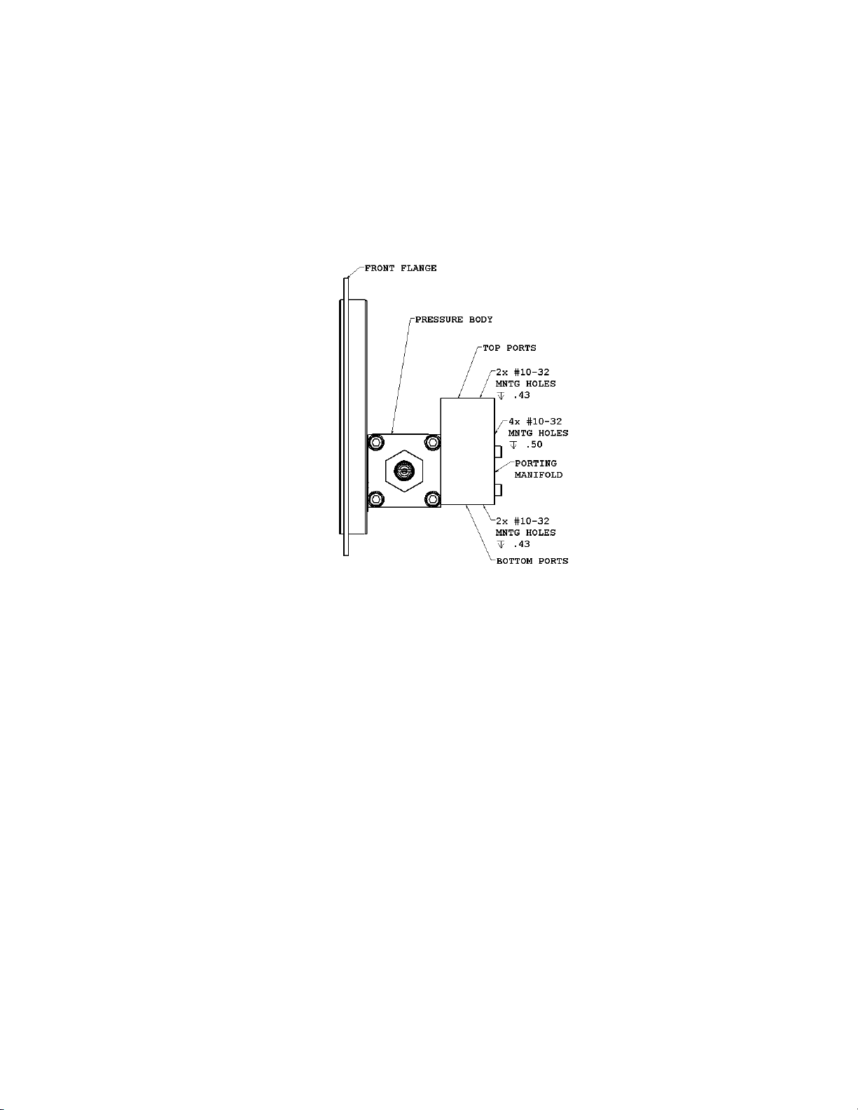
This gauge is a 1516 with a porting manifold mounted to the
back. The mounting holes on the back/bottom and the process
ports mimic those found on the Barton 227C gauge. In fact the
relative position of the mounting holes and the process ports is
exactly the same as the Barton gauge, allowing you to remove
the Barton gauge and install this unit in minutes without
changing the position of the mounting screws and piping.
If you have a Barton mounting bracket, you can reuse it on our
gauge.
The gauge can be mounted to a bracket using the mounting
holes on the back of the pressure body, or panel mounted
using the three holes on the dial case front flange.
Most differential pressure gauges have two pressure ports,
one for high pressure and one for a low pressure connection.
Model 1536 has four ¼ inch FNPT ports. Two are high
pressure ports and two are low pressure ports. The ports are
marked HI for high and LO for low.
HI-Left ports –standard
The standard configuration, called Hi-Left, has the two high
pressure ports on the left and two low pressure ports on the
right, as you read the dial
Hi-Right ports –no charge option
An optional Hi-Right configuration has the high pressure ports
on the right and the low pressure ports on the left, as you read
the dial.
High Pressure on wrong side?
If you have received a gauge with the porting reversed for your
setup, another porting manifold with opposite porting can be
sent to you. You can easily retrofit the new porting manifold in
the field. Please contact Orange Research to have this sent to
you.
To retrofit your unit with another porting manifold, remove the
four bolts on the back of the unit holding the manifold. (Do not
remove the four bolts on the side of the unit!) Remove the two
O-rings and assemble the new porting manifold using the
same four bolts and the new O-rings. Be sure to lightly grease
the new O-rings so they slide into position properly.
The Hi-Left porting manifold on the back is scribed with an “A”
on the top, while the Hi-Right porting manifold is scribed with a
“B”. Please refer to the necessary porting manifold as Hi-Right,
Hi-Left or as “A” or “B” so we can be sure to send you the
proper manifold. Please also identify the type of O-ring
material used on your unit, since we will need to send two
more new O-rings, and they will have to match what you have
now.
Only two of the four ports are required to measure differential
pressure. The additional high and low ports can be used for
bleed ports, to connect a pressure gauge or other instrument,
or simply to connect additional piping.
Two port plugs are supplied with each unit. Install them in any
ports not being used in your installation. Teflon tape should be
used on all port connections. Two or three wraps of Teflon
tape are recommended.
If you have selected the ½ inch NPT ports option, you will have
received four ¼ inch to ½ inch adapters. Install them in as
many ports as required with Teflon tape.
- For a Brass body the adapters are Brass
- For an Aluminum body the adapters are SS
Filters
For filter applications, the high pressure port would be piped to
the inlet of the filter and the low pressure port would be piped
to the outlet of the filter.
Cryogenic Tanks
In the case of a cryogenic tank the high pressure port would
be mated to the bottom of the tank while the low pressure port
would be mated to the top of the tank, called the vapor space
or the ullage.
DP Flow
For dp flow measurement, the high pressure port would be
installed on the inlet of the primary flow element while the low
pressure port would be installed on the outlet of the flow
element.