ORBINOX CANADA, ORBINOX USA, ORBINOX BRAZIL, ORBINOX CHILE, ORBINOX PERU, ORBINOX SPAIN, ORBINOX UK, ORBINOX FRANCE, ORBINOX GERMANY, ORBINOX INDIA, ORBINOX CHINA, ORBINOX S.E.A.
ORBINOX reserves the right to change specifications without notice
In most cases, the operating floor level is located substantially
higher than the opening. In order to be able to operate the gate,
stem extensions are necessary. Stem guides are used to limit the
“unsupported” length of the stem extension in order to avoid any
buckling failure. The stem guide has a HWMPE guide to reduce
friction between the guide and the extension
NON-RISING STEM CONFIGURATION.
As standard, non-rising stem gate configurations are used with self-
contained frame designs. Therefore, the stem extension does not
support the axial load (only torque) and less wall brackets are
required. As a general rule, a stem guide should be installed every
10 feet (3 meters) of unsupported stem extension.
RISING STEM CONFIGURATION
As standard, rising stem gate configurations are used with open-
frame designs. Therefore, the stem extension has to support the
axial load when the gate is operated. In consequence, the use of
stem guides is critical to avoid any buckling failure. As a general
rule, a stem guide should be installed every 6½ feet (2 meters) of
unsupported stem extension.
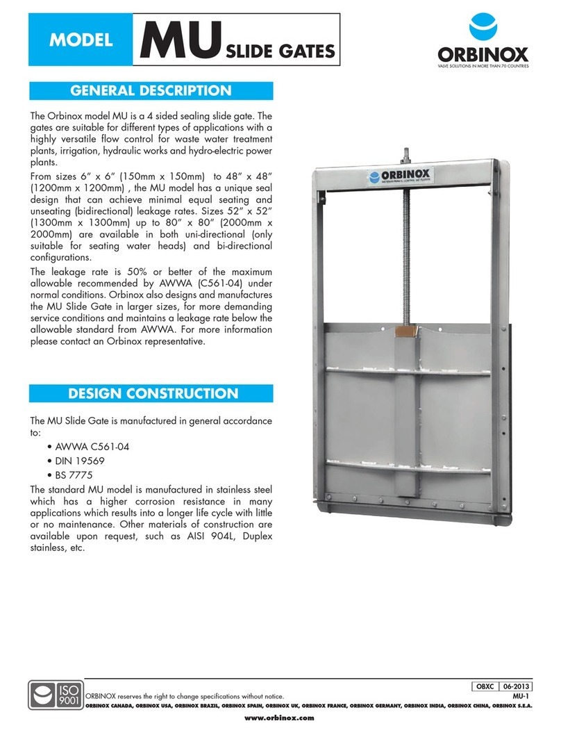
INSTALLATION, OPERATION AND MAINTENANCE
Slide Gate
(Rising Stem, Open Frame)
This section briefly describes the installation, operation
and maintenance of MU Slide Gates. For more detailed
information please refer to the “MU IOM Manual”
INSTALLATION:
ORBINOX MU Slide Gates are installed by means of
anchor bolts. Depending on the size and working
conditions they shall be either of the mechanical or
chemical type (see table below). In order to avoid
leakage between the concrete wall and the frame,
ORBINOX recommends the use of construction sealant
equivalent to Sikabond Construction Sealant (200ml
per meter of opening perimeter)
The minimum concrete strength shall be 3,000PSI (20.7
MPa). The concrete construction tolerance (flatness, levelness
and plumbness) shall be in accordance to ACI 117-10. For
detailed information about type, size and quantity of the
required anchor bolts for installation, please refer to the
notes on the “General Arrangement Drawing”
MAINTENANCE AND OPERATION:
The ORBINOX MU Slide Gates need practically no
maintenance. The stem should be kept lubricated and seals
should be replaced if damaged. The MU Slide Gate is
closed by applying a clockwise rotation. Applying excessive
force on the operator when closing the gate may cause
damage to the stem
Recommended (Hilti or
equivalent)
6”x 6” -48”x48”
(150mmx150mm-1200mmx1200mm)
Seating and Un-Seating
(Bi-Directional)
Wall Mount: Stud Type
Mechanical
Anchor Bolts and Bolt Type
Mechanical Anchor Bolts
Hilti “Kwik 3”
& Hilti “HSL”
52x 52”-160”x160”
(1300mmx1300mm-4000mmx4000mm)
Seating and Un-Seating
(Bi-Directional)
Embedded in concrete:
Optional wall mount + chemical
anchor bolts
52x 52”-160”x160”
(1300mmx1300mm-4000mmx4000mm)
Seating
(Uni-Directional)
Wall mount: Stud Type
Mechanical Anchor Bolts
Stem Guide & Slide Stopper


