Orca OM1907-AC User manual

Installation and User Manual
Smoke Alarm Model OM1907-AC

Product Description
This photoelectric smoke alarm is designed to detect smoke from emerging household
res and alert occupiers if properly installed and maintained, providing extra time to
safely evacuate the home. This product is designed for household or residential use.
This product complies with NZ laws and is certied to AS3 86:2014.
Product Overview
Red LED
Green LED
Test/Hush button
Speaker grill
Model: OM1907-AC
2

Features
• 220V~ 240V Mains powered, 50Hz, 80mA.
• Single station and / or inter-connectable up to 24 units.
• Photoelectric sensor.
• 9V Replaceable battery back-up.
• Test & hush control.
• Low battery indication.
Important In ormation
• Please read these instructions before installing the alarm.
• This alarm should be installed by a registered electrician.
• There are no parts within alarm that should be replaced by the user.
• Disconnecting alarm from the mounting base and/or removing the 9V battery will
render this smoke alarm inactive.
• Alarm has an expected service life of 10 years under normal conditions.
• This alarm should be replaced 10 years after its installation date.
3

Recommended Location o Alarms
• Emerging smoke rises to the ceiling and spreads horizontally. Mounting the alarm on
the ceiling close to the centre of the room provides the best protection. Ceiling
mounting, rather than wall mounting, is preferred in normal residential construction.
• When mounting alarms on the ceiling locate it at least 300mm away from the side
wall and 300mm away from any corner. (see diagram overleaf).
• When mounting alarms on a wall, use the inside wall. The recommended position is
between 300mm and 500mm o the ceiling. (see diagram overleaf).
• When mounting the alarm at the apex of a sloping ceiling it should be located at
least 500mm away from the apex but should not exceed 1500mm (see diagram
overleaf).
• Locate at least one alarm on every oor level.
• Locate an alarm in every room where electrical appliances are operated (i.e. Portable
heaters or humidiers).
• Locate an alarm for each separate sleeping area in the immediate vicinity of the
bedrooms. Monitor the exit path as the bedrooms are usually farthest from an exit.
• Locate smoke alarm at both ends of a bedroom hallway or large room if the hallway
or room is more than 9m long.
Note: The performance of smoke alarms mounted on walls is unpredictable and this
mounting position is not recommended when ceiling mounting can be implemented.
4

Recommended Location o Alarms
• Locate additional alarms to monitor any stairway as stairways act like chimneys for
smoke and heat.
• For mobile home installation select location carefully to avoid thermal barrier that
may form at the ceiling. For more details see Mobile Home Installation.
• Do not locate smoke alarms in kitchen areas due to potential nuisance alarms from
cooking fumes.
• Incorrect orientation of smoke alarm may decrease operation eectiveness.
DEAD
AIR SPACE
DEAD AIR
SPACE
HEAT &
SMOKE
FROM
FIRE
HEAT & SMOKE
FROM FIRE
CEILING
ACCEPTABLE HERE
BEST
HERE NEVER
HERE
Installation
5

Mobile Home Installation
• Modern mobile homes have been designed and insulated to be energy ecient.
Install smoke alarms as recommended (refer to Recommended Locations).
• In older mobile homes that are not well insulated compared to present standards,
extreme heat or cold can be transferred from the outside through poorly insulated
walls and the roof. This may create a thermal barrier which can prevent smoke from
reaching a smoke alarm mounted on the ceiling. In such units, install smoke alarm on
inside partition between 300mm and 500mm from the ceiling.
• If you are not sure about the insulation in your mobile home, or if you notice the
walls and ceilings are either hot or cold, install alarm on an inside wall. For minimum
protection, install one alarm close to the bedrooms.
Note: Test your smoke alarm operation after mobile home vehicle has been in storage,
before each trip and at least once a week during use.
Avoid these Locations
• Do not locate your alarm in the garage - vehicles and workshop equipment can cause
fumes.
• Do not locate your alarm in front of forced air supply ducts used for heating and air
conditioning and other high air ow areas.
• Do not locate your alarm less than 500mm from the peak of an "A" frame type ceiling.
•
Do not locate your alarm in areas where temperatures may fall below 5°C or rise above
40°C, or in humidity higher than 90% as these conditions may reduce battery life.
6

Avoid these Locations
• Avoid dusty areas, dust particles may cause smoke alarm to false alarm or fail to alarm.
• Avoid very humid areas or near a bathroom or laundry, moisture can cause false alarm.
• Avoid insect-infested areas.
• Do not locate alarm within 0.9m of the following: the door to a kitchen, the door to a
bathroom containing a tub or shower, a ceiling or whole house ventilating fan, or
other high ow areas.
• Avoid locating near uorescent lights or other electrical equipment. Electronic
magnetic interferences or“noise”may cause nuisance alarms or chirping.
• Smoke alarms are not to be used with detector guards unless the combination (alarm
and guard) has been evaluated and found suitable for that purpose.
False Alarms
• This smoke alarm is designed to minimize false alarms. Smoking will not normally set
o the alarm unless smoke is blown directly into the alarm.
• Combustion particles from cooking may set o the alarm if the alarm is located close
to the kitchen cooking surface or appliance.
• Large quantities of combustion particles are generated from spills and over-boil.
• An alarm with a Hush Control device is preferable near a kitchen environment for this
reason.
Alarm Cleaning
To prevent false alarming caused by buildup of dust and insects, remove base plate
from alarm (see pg 8) and carefully vacuum all gaps and openings with the brush
attachment on your household vacuum cleaner. Repeat procedure every 6 months.

False Alarms
• Photoelectric type smoke alarms are less prone to false alarm near kitchen areas than
ionisation type smoke alarms.
• If the alarm does sound, check for re rst. If a re is discovered, escape quickly and
call the Fire Brigade. If no re is present, check to see if one of the reasons listed on
previous page may have activated the alarm.
How To Remove Smoke Alarm rom Base Plate
• Switch o mains power.
• Remove Tamper Locking Screw (if installed).
• Look for‘PUSH to OPEN‘ (Fig.3).
• Push rmly towards arrow until smoke alarm unhinges from base plate.
(Fig.3)
Installation
• This Smoke Alarm can only interconnect with other alarms of the same model.
Interconnection with other brands may cause damage or result in a shock or re risk
and void warranty.
8

Installation
• These smoke alarms must be installed by a registered electrician.
• Due to“noise”from electromagnetic interference, no more than 24 of these smoke
alarms may be interconnected.
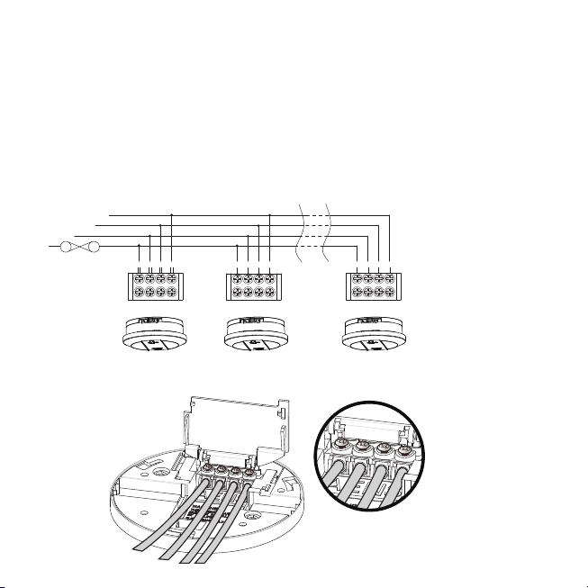
• There are three terminals in the supply terminal block, marked A, S, N. It is important
that the alarm be wired correctly to ensure correct operation. Incorrect wiring to the
Smoke Alarm will damage the unit and void the warranty.
• A total maximum of 250 meters (820 feet) of wire can be used in interconnecting
smoke alarms.
• All nal sub-circuit conductors including the signal conductor must be a minimum
size of 1mm with 250V grade insulation.
• Interconnected Smoke Alarms must be connected to the same nal subcircuit.
• Do not use any wire that could later be confused with the normal house wires for the
interconnect wire. For example, green/yellow earth wire.
• Do not connect AC power wires to S interconnect terminal. These will damage smoke
alarms.
• Do not connect the S interconnect wire to any device, except the S interconnect
terminal of the smoke alarm. Otherwise, the smoke alarm will be damaged.
• Smoke alarms should be interconnected only within the connes of a single family
living unit. If smoke alarms are interconnected between dierent units, there may be
excessive nuisance alarms. Residents may not be aware that smoke alarms are being
tested or that it is a nuisance alarm caused by cooking etc.
9

1
N
s
A
224
MAXIMUM OF 24 DEVICES
CONNECTION TO A
FUSE ON
CIRCUIT
BREAKER
ORCA
INTERCONNECT
SMOKE ALARM
ORCA
INTERCONNECT
SMOKE ALARM
ORCA
INTERCONNECT
SMOKE ALARM
Figure 1
Installation
• Terminals are marked as follows:
A= ACTIVE
E= EARTH
N= NEUTRAL
S= SWITCH WIRE (FOR INTERCONNECTION ONLY)
Warning: Connecting the Switch wire terminal to any other supply conductor may result in
damage to the alarm, failure to operate or shock hazard and void the warranty of the alarm.
EN
s
AEN
s
AE
N
s
AEN
s
AEN
s
AE
10

Installation
• When interconnected, all Smoke Alarms will sound upon activation.
• Warning: This alarm cannot be operated from power derived from a square wave,
modied square wave or modied sine wave inverter. These type of inverters are
sometimes used to supply power to the structure in o grid installations, such as
solar or wind derived power sources. These power sources produce high peak
voltages that will damage the alarm.
• Orca recommend that the smoke alarms are installed on their own subcircuit to avoid
false alarms and nuisance chirping that may be caused by electromagnetic
interferences from other electrical equipment.
Mounting Instructions
• Separate Smoke Alarm from mounting base by sliding cover o.
• Connect supply cable to terminal block and x terminal cover.
• The models contain a battery pull tab for your convenience. Tab must be removed to
activate battery backup and provide power to the unit in the event of mains power
loss.
• Pull out the battery pull tab.
• If you want to replace the battery, please press the battery reminder tab down into
the battery compartment while inserting the battery. Caution: If the battery reminder
tab is not held down in the battery compartment by the battery, the unit will not
attach to the mounting plate.
• Align and slide smoke alarm up onto mounting base then slide in the reverse
direction of arrow to ensure proper connection.
11

Figure 2:Lock the smoke alarm base along with
the spindle. then tighten the screws with a screwdriver
(screws (PA3*8) are in the accessory bag).
Figure 1:Please insert the smoke
Installation
• Switch on power and check the green light on alarm cover. It should glow when
mains power is switched on indicating that the smoke alarm is properly connected to
the mounting base.
• If required, secure Tamper Proof Locking Screw (supplied) to smoke alarm.
• Test alarm by pressing Test button
until the alarm sounds.
alarm's latch into it's base horizontally.
Figure 3: Use a screwdriver to loosen the
screw and then press the button to open
the battery compartment.
Figure 4:Please push in the direction
of the arrow rmly and the smoke
alarm can be released from the base.
12

Figure 5
Installation
Test & Battery Backup
• Alarm will not function without a properly installed battery. It is equipped with a
battery lockout feature which prevents the battery door from closing if a battery is
not installed correctly (See Figure 5).
• To ensure proper operation, depress the Test button for at least 5 seconds, or until the
alarm sounds (without the AC power connected). All interconnected, battery backed-
up alarms, should respond.
• Caution: Due to the loudness (85 decibels) of the alarm, always stand an arms-length
away from the unit when testing.
• Turn on the AC power. The green LED power indicator should be lit when the alarm is
operating from AC power.
• Conrm unit operation by pressing the Test button again.
• The smoke alarm is operating once AC power is applied, a fresh battery is installed
and testing is complete. When the smoke alarm senses products of combustion, the
horn will sound a loud (85db) alarm until the sensing chamber is cleared of smoke
particles.
13

Operation, Testing & Maintenance
• The smoke alarm is operational once all wires are properly connected, a fresh battery
is installed, the smoke alarm is correctly installed on the mounting base and the
alarm has been tested.
Red LED
• Stand-by condition: will ash once approximately every 40 seconds to indicate unit is
functioning properly.
• Alarm condition: the Red LED will ash once every second. For interconnected units,
the initial smoke alarm Red LED will ash once every second. All other units will
sound but the Red LED will not be on or ashing.
Green LED
• AC Mains-ON Indicator: indicates that the unit is operating with AC power. If this LED
goes out, it indicates that the AC power is o.
False Alarm Hush Control Feature
Note: ense smoke will over-ride Hush control feature and sound a continuous alarm.
• This smoke alarm has the capability of being temporarily desensitized for
approximately 8-10 minutes by pressing the“Test / Hush”button on the smoke alarm.
• After pressing the“Test / Hush”button, the alarm will silence immediately but will
automatically reactivate after approximately 8-10 minutes and sound the alarm if
particles of combustion are still present.
• The“HUSH” feature may be used repeatedly until the air has cleared.
Warning: Before using HUSH feature, identify the source of smoke and be certain that a safe
condition exists.
14

Function LED Status Recommendation
Normal Green light ON. Green LED indicates the AC mains power
is present.
Normal Red light FLASHING
every 33 seconds. Red LED ashes every 33 seconds if
normal. The smoke alarm performs a self
test every 33 seconds. The battery and
electronics is tested for the life of the
unit.
Alarm mode Red light ashing once
every second. Smoke
alarm activated.
Repeat 3 long beeps (ISO8201) that
indicate smoke alarm has activated and
is in alarm mode.
Alarm mode Red light is OFF. Smoke
alarm activated. Smoke alarm in full alarm, repeat 3 long
beeps (ISO8201). Other interconnected
units may have activated the alarm.
Check other smoke alarms or devices.
Hush mode Green light ON. Red
light ashes every 10
seconds and no chirp.
The“HUSH” feature has the capability of
temporarily desensitizing the alarm
circuit fo approximately 8 minutes.
Low Battery Green light ON, Flashing
red light every 33
seconds.
Smoke alarm chirps every 33 Seconds.
May indicate low battery status. Replace
the battery.
Operation, Testing & Maintenance
Operation
15

--+-
Battery Installation, Replacement & Test
Battery Installation
The smoke alarm uses one 9V battery to automatically provide back-up power to the
alarm if AC power fails. The battery will operate the alarm for approximately one to three
months with AC power o.
The smoke alarm has a low battery indicator that will cause the unit to chirp and ash the
Red LED at approximately 33 second intervals for a minimum of 30 days. Missing battery
with main power connected will cause the unit to chirp and ash the Red LED at
approximately 33 second intervals.
Replace battery when chirping occurs.To ensure proper operation, the battery should be
replaced once a year.
To replace battery, remove alarm from mounting base (see section 6.2) and remove the
battery from compartment.Replace the old battery with a new one.
Use only the following 9 volt batteries for smoke alarm replacement.
Alkaline Type: ENERGIZER 522, DURACELL MN1604,
MX1604
Carbon Zinc Type: Gold Peak 1604E.
These batteries can be purchased at your local retail
outlet or supermarket.
Caution: Use only specied batteries. Use of dierent
batteries may have a detrimental eect on operation or
may cause the batteries to explode resulting in injury or
re.
16

Battery Installation, Replacement & Test
• Use only batteries specied on the label.
• Fold Red Battery Lever down into compartment with fresh replacement battery. If the
Red Battery Lever is not held down in the battery compartment by the battery, the
smoke alarm will not close and will not be operational.
Warning: Use of inferior batteries or incorrect types may cause a malfunction of the Alarm.
When replacing the battery and on reconnection of the detector to the base plate, make sure
that the detector is fully connected and flush with the base plate. Verify that the Green LE is
ON after reinstalling the alarm on the base plate.
Battery Test
• Switch o mains power. The Green LED on the smoke alarm will be OFF.
• Test alarm by pressing the Test Button for a few seconds. This should sound the alarm.
• If the battery module has a fault, the alarm will chirp every 33 seconds.
• Watch the Red LED for about 33 seconds. It should ash at least once.
• Switch on mains power only when smoke alarm passes the above tests. The Green
LED on the smoke alarm will come ON.
Note: Weekly testing is recommended!
1

Repairs & Services
• If the smoke alarm is defective in any way, do not tamper with the unit. Return the
unit to your supplier (See warranty for instructions on in-warranty returns). There will
be a service charge for repairing units out of warranty.
Good Sa ety Habits
The use of this product should not be seen as a substitute for basic safety precaution in
the prevention of FIRE.
There are situations where a smoke alarm may not be eective to protect against re:
• smoking in bed;
• leaving children home alone;
• cleaning with ammable liquids, such as petrol.
The Limitations o Smoke Alarms
• Smoke alarms are devices that can provide early warning of possible developing res
at a reasonable cost.
• Smoke alarms have certain limitations. For battery powered smoke alarms, the
battery must be in good condition and installed properly.
• AC powered alarms will not operate if AC power has been cut o, such as by an
electrical fault, open fuse or circuit-breaker, or re. However, the battery back-up will
activate the alarm if in good working order.
18

The Limitations o Smoke Alarms
• Smoke alarms must be tested regularly to ensure that the batteries and alarm circuit
are in good operating condition.
• Smoke alarms cannot provide an alarm if smoke does not reach the alarm. Therefore,
smoke alarm may not sense res starting in chimneys, walls, on roofs, on the other
side of a closed door, or on a dierent oor.
• If the alarm is located outside the bedrooms, or on a dierent oor, it may not wake
up a sound sleeper. A smoke alarm in the bedroom, therefore, is recommended.
• Smoke alarms have been signicant in saving lives in many parts of the world. Hence,
the use of this product does not substitute for basic prevention and total protection.
• Although smoke alarms can help save lives by providing early warning of a re, they
are not a substitute for an insurance policy.
• This smoke alarm alone will not alert the hearing impaired. Use special purpose
smoke alarm with lights or vibrating devices, for those hard of hearing.
• Heat alarms are available to oer greater security when used with smoke alarms.
• Life safety from re in residential occupancies is based on early notication to
occupants of the need to escape, followed by appropriate egress actions by
occupants. Fire warning systems for dwelling units are capable of protecting about
half of the population in potentially fatal res. Victims are often intimate with the re,
too old, young, or physically, mentally impaired that they cannot escape even when
warned early that escape should be possible. For these people, other strategies such
as protection-in-place or assisted escape or rescue are necessary.
19

Develop & Practice a Plan o Escape
Basic Escape Plan:
• Make a oor plan indicating all doors and windows and at least two escape routes
from each room. Second storey windows may need a rope or chain ladder.
• Have a family meeting and discuss your escape plan, showing everyone what to do in
case of re.
• Determine a place outside your home where all of you can meet, if a re occurs.
• Familiarize everyone with the sound of the smoke alarm and practice leaving your
home when they hear it.
• Practice a re drill at least every six months including drills at nights. Practice allows
you to test your plan before an emergency. You may not be able to reach your
children. It is important that they know what to do!
• Install and maintain re extinguishers on every level of the home and in the kitchen,
basement and garage. Know how to use a re extinguisher prior to an emergency.
• Current studies have shown smoke alarms may not awaken all sleeping individuals,
and that it is the responsibility of individuals in the household that are capable of
assisting others to provide assistance to those who may not be awakened by the
alarm sound, or to those who may be incapable of safely evacuating the area
unassisted.
20
Table of contents
Other Orca Smoke Alarm manuals
Popular Smoke Alarm manuals by other brands

Gentex
Gentex Smarter Vision GN-200 Series Installation Instructions - Owner's/User's Information Manual

Edwards
Edwards LaserSense 100 Installer's handbook

BRK electronic
BRK electronic SC7010LBLV user manual

FIREWOLF
FIREWOLF FW-4 installation instructions

Mini Gadgets
Mini Gadgets Bush Baby BB4KWiFiSmoke user manual

DSC
DSC MN-240 series Installation and operation instructions