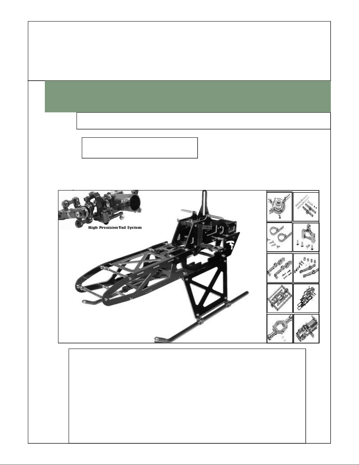
WELCOME TO 3DX450 R/C MODEL PRODUCTS
Thank you for buying this Product. The 3DX 450 FSE Helicopter is designed as easy to use, full featured
Helicopter R/C model capable of all forms of rotary flight. Please read the manual carefully before assembling the
model, and follow all precautions and recommendations located within the manual. Besure to retain the manual for
future reference, routine maintenance, and tuning.
This helicopter features the best design available on the Micro-Heli market to date, providing flying stability for be-
ginners, full aerobic capability for advanced fliers, and unsurpassed reliability for customer support
R/C helicopters, including the 3DX 450 FSE are not toys. R/C helicopters utilize various high-tech products and
technologies to provide superior performance. The rotating blades on the model spin at high speed and can cause
potential risk or injury if used improperly. It is mandatory that you observe all RIC safety rules and adhere to local
laws as applicable. We recommend that you contact your local hobby store and inquire about safety, rules, regula-
tions, and local laws and statutes regarding R/C model operation in your area. Please make sure to be conscious of
your own personal safety and the safety of others and your environment when operating all products.
When used properly, this R/C product will provide years of R/C entertainment. We recommend that you obtain the
assistance of an experienced pilot before attempting to fly our products for the first time. A local expert is the best
way to properly assemble, setup, and fly your model for the first time. The 3DX 450 FSE requires a certain degree
of skill to operate, and is a consumer item. Any damage or dissatisfaction as a result of accidents or modifications
are not covered by any warrantee and cannot be returned for repair or replacement. Please contact our distributors
for free technical consultation and parts at discounted rates when you experience problems during operation or
maintenance.
Note: Fly only in safe areas, away from other people. Do not operate R/C aircraft within the vicinity of homes or
crowds of people. R/C aircraft are prone to accidents, failures, and crashes due to a variety of reasons including,
lack of maintenance, pilot error, and radio interference. Pilots are responsible for their actions and damage or injury
occurring during the operation or as of a result of R/C aircraft models.
SAFTY NOTES
IMPORTANT NOTES
1. Locate an appropriate locaton:
R/C helicopters fly at high speed, thus posing a certain degree of potential danger.
Choose an appropriate flying site consisting of flat, smooth ground, a clear open field, or a large open room, such
as gymnasium or warehouse without obstacles. Do not fly near buildings, high voltage cables, or trees to ensure
the safety of yourself, others, and your model. Do not fly your model in inclement weather, such as rain, wind,
snow, or darkness.
2. Obtain the assistance of an experienced pilot:
Before turning on your model and transmitter, check to make sure no one else is operating on the same frequency.
Frequency interference can cause your model, or other models to crash. The guidance provided by an experienced
pilot will be invaluable for the assembly, tuning, trimming, and actual first flight.
(Recommend you to practice with simulated flying software.)
3. Always be aware of the rotating blades:
During the operation of the helicopter, the main rotor and tail rotor will be spinning at a high rate of speed. The
blades are capable of inflicting serious bodily injury and damage to the environment. Be conscious of your actions,
and careful to keep your face, eyes, hands, and loose clothing away from the blades. Always fly the model a safe
distance from yourself and others, as well as surrounding objects. Never take your eyes off the model or leave it
unattended while it is turned on. Immediately turn off the model and transmitter when you have landed the model.
Page 2 Note’s Before Starting