manuals.online logo
Brands
  1. Home
  2. •
  3. Brands
  4. •
  5. THE WORLD MODELS
  6. •
  7. Toy
  8. •
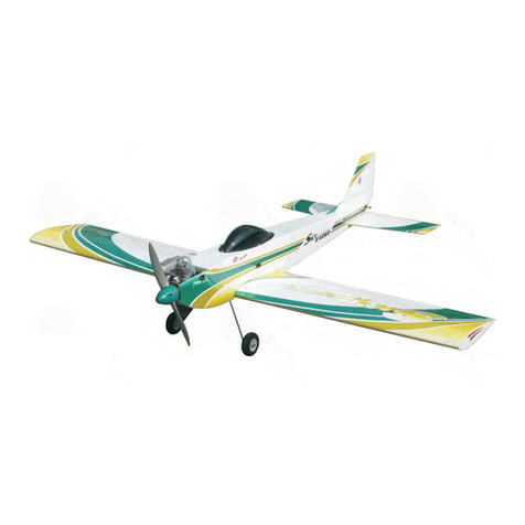
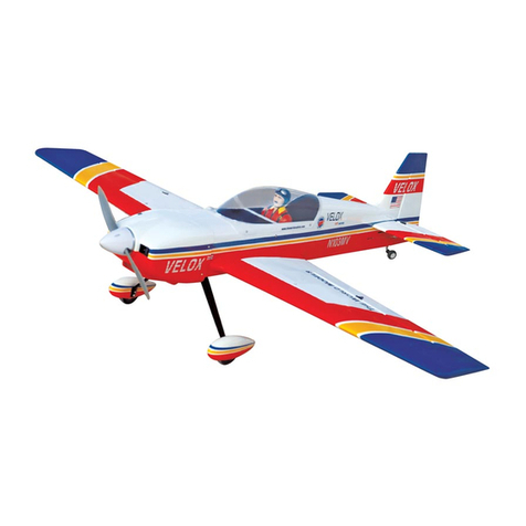
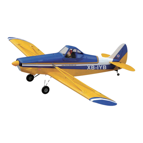
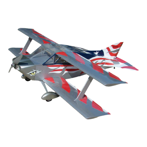
  9. THE WORLD MODELS ZEN 50 User manual

THE WORLD MODELS ZEN 50 User manual

Wing Span
Wing Area
Flying Weight
Fuselage Length
54.0 in / 1370mm
564 sq in / 36.4 sq dm
6.0 lbs / 2650g
54 in / 1370mm
Warning !This model is not a toy.
It is designed for maximum performance. Please seek advice if one is not familiar with this kind
of engine powered precision model. Operating this model without prior preparation may cause
injuries. Remember, safety is the most important thing. Always keep this instruction manual at
hand for quick reference.
THE WORLD MODELS
MANUFACTURING CO. LTD.
FACTORY PRE-FABRICATED
ALMOST-READY-TO-FLY (ARF) SERIES
MADE IN CHINA
www.theworldmodels.com
0.40 cu.in. displacement 2-cycle
0.52 cu.in. displacement 4-cycle
Radio required : 5 channels, 6 servos airplane radio
* Specifications are subject to change without notice.*
Specifications
INSTRUCTION MANUALINSTRUCTION MANUAL
D
E
A
R
-
Y
T
-
T
S
O
O
-
F
M
L
L
Y
A
P. 1
I N D E XI N D E X
BEFORE YOU BEGINBEFORE YOU BEGIN
PARTS LISTPARTS LIST
ASSEMBLYASSEMBLY
SAFETY PRECAUTIONSSAFETY PRECAUTIONS
P. 1P. 1
P. 2P. 2
P. 3 - 10P. 3 - 10
P. 11P. 11
BEFORE YOU BEGIN
Do not overlook this symbol!
Cut off shaded portion.
Ensure smooth non-binding
movement while assembling.
Apply instant glue
(C.A.glue, super glue.)
Assemble left and right
sides the same way.
Peel off shaded portion
covering film.
Pay close attention here!
Apply epoxy glue.
Pierce the shaded portion
covering film.
Must be purchased separately!
Drill holes with the specified
diameter (here: 3mm).
3mm
Warning!
Check all parts. If you find any defective or missing parts contact your local dealer. Please DRY FIT
and check for defects for all parts that will require CA or Epoxy for final assembly. Any parts you
find to be defective after the gluing process may be difficult to remove for warranty replacement. The
manufacturer will replace any defective parts. but will extend to the parts that are good before
not
gluing to defective parts during assembly.
Read through the manual before you begin, so you will have an overall idea of what to do.
Symbols used throughout this instruction manual comprise of the following : -
1
2
3
Parts List
P. 2
1. FUSELAGE & BELLY PAN --1 set
2. MAIN WING --1 pc.
3. STABILIZER & ELEVATOR --1 set
4. RUDDER --1 set
5. CANOPY --1 set
6. COWLING --1 pc.
TRANSPARENT DUMMY COWLING --1 pc.
7. PILOT (#PC001050A) --1 pc.
8. SPINNER Ø62mm --1 pc.
9. ENGINE MOUNT PL5111-050 --1set
10.FUEL TANK 320cc --1 set
11.SPONGE 10x80x200mm (For Radio Equipment) --2 pcs
12.TAIL LANDING GEAR --1 set
13.MAIN WHEEL Ø50mm --2 pcs
14.TAIL WHEEL Ø23mm --1 pc.
15.PUSHROD , PUSHWIRE & PULLWIRE:--
COPPER TUBE d2.0xD2.4x8mm (For Rudder) --4 pcs
METAL ROD Ø1.8x27mm (For Rudder) --2 pcs
METAL ROD Ø1.8x27mm w/Threads (For Rudder) --2 pcs
METAL ROD Ø1.8x80mm (For Elevator) --1 pc.
METAL ROD Ø1.8x105mm w/Threads (For Aileron) --2 pcs
METAL ROD Ø1.8x160mm w/Threads (For Elevator) --1 pc.
METAL ROD Ø1.8x165mm w/Threads (For Elevator) --1 pc.
PLASTIC TUBE d2xD3x700mm (For Elevator) --2 pcs
PLASTIC TUBE d2.5xD3x50mm (For Rudder) --2 pcs
WOODEN ROD Ø8x580mm (For Elevator) --1 pc.
16.THROTTLE PUSHWIRE Ø1.2x420mm
w/Plastic tubed2xD3x200mm --1 set
17.WOODEN PARTS:--
BALSA 10x10x91mm (For Fixing Fuel Tank) --1 pc.
PLYWOOD 1x10x20mm (For Belly Pan ) --2 pcs
PLYWOOD 6x20x33mm (For Belly Pan) --2 pcs
PLYWOOD 3x61x85.5mm (Rudder Servo Stand) --1 pc.
PLYWOOD 3x61x87.5mm
(Throttle & Elevator Servos Stand) --1 pc.
PLYWOOD 3x10x77mm (For Rudder Servo) --2 pcs
PLYWOOD 3x10x79mm
(For Throttle & Elevator Servos) --2 pcs
18.PLASTIC PARTS:--
CLEVIS --8 pcs
SILICON GROMMET d1.5xD6.5mm
(For Cowling, Canopy & Belly Pan)--12 pcs
HORN --4 sets
HORN (w/o-Base For Rudder) --2 sets
STRAPER --3 pcs
19.METAL PARTS:--
LINKAGE CONNECTOR 2.1mm --3 sets
COLLAR 2.1mm w/set screw --1 set
COLLAR 4.1mm w/set screw --2 sets
NUT2mm --2 pcs
NUT 3.5mm --8 pcs
SCREW PA 3x12mm --2 pcs
SCREW PM 2x16mm --4 pcs
SCREW PM 2x20mm --2 pcs
SCREW PM 2x25mm --4 pcs
SCREW PM 3.5x30mm --4 pcs
SCREW PM 4x25mm --4 pcs
SCREW PM 4x35mm --2 pcs
SCREW PWA2.3x8mm --6 pcs
SCREW PWA2.3X12mm--4 pcs
WASHER d3.5xD8mm --8 pcs
WASHER d4xD9mm --4 pcs
WASHER d4xD15mm --2 pcs
20.FUEL TUBE Ø6x5mm --9 pcs
HEAT-SHRINK TUBE Ø8x40mm --2 pcs
21.DECALS: ST 200 035 --1 set
P.3
1
Aileron Servo
3
Aileron Servo
2
Main Wing Peel off shaded portion
covering film.
Peel shaded
Portion covering
film.
PM 2x25mm Screw
Ø1.8x105mm
PM 2x25mm
Clevis
Fuel Tube
Ø6x5mm
4
Stabilizer
6
Landing Gear Servo
5
Main Landing Gear
P.4
Linkage Stopper
3 X 3mm Set Screw
L i n k a g e C o n n e c t o r
2mm Nut
2mm Washer
KA 3x14mm Screw
3mm Set Screw
4.1mm Collar
Wheel Ø50mm
1.5mm
26mm Storke
Wheels up position
T L-s do i e
To R-side
Wheels down position
3mm Set Screw KA 3x14mm
4.1mm Collar
26mm Storke
7
Engine Mount
9
Tail Landing Gear
8
Vertical Fin/Rudder
P.5
PA 3x12m Screw
3mm Set Screw
2.1mm Collar
Wheel Ø23mm
PA 3x12mm 2mm
1.5mm
PM 4x25mm Screw
4mm Washer
Engine Mount
PL5111-050
4mm
PM 4x25mm
Apply thread locker
to screws.
Blind nuts are off-centered to keep
the spinner at the fuselage axis.
3mm Set Screw
2.1mm Collar
10
Elevator Pushrod
12
Engine
11
Fuel Tank
P.6
Install Balsa & Plywood for fixing fuel tank
Balsa 10x10x91mm
Fuel Tank
Bottom View
Fuel Tank 320cc
PM 3.5x30mm Screw
d3.5xD8mm Washer
d3.5mm Nut
3.5mm
Plastic tube
d2xd3x200mm
Throttle Pushwire
Ø1.2x420mm
PM 3.5mmx30mm
Install Engine position
Spinner
Ø62mm
Fire
Wall
115mm
4.5in.
Illustratuin is for inverted mounting.
You can mount the engine upright
or sideways simply by rotating the
engine mount. thrust angles will
not be affected.
3.5mm
1.8x80mm heat-shrink Tube
8x580mm
Ø1.8x165mm
Ø1.8x160mm
5mm
1.8x165mm
1.8x160mm
Clevis
Fuel Tube
Ø6x5mm
Be careful not to scorch
the heat-shrink tube!
COMPLETED
13
Servo Set
15
Elevator Pushrod
14
Elevator Pushrod
P.7
Linkage Connector
3 X 3mm Set Screw
L i n k a g e C o n n e c t o r
2mm Nut
2mm Washer
Elevator Pushrod
Plastic Tube
d2xD3x700mm
Plastic Tube
d2.5xD4x50mm
Elevator Pushrod
PM 2x16mm
Fuel Tube
Ø6x5mm
PM 2x16mm Screw
Bottom ViewBottom View
Throttle Pushwire
3mm
2mm
Included with the Radio Set.
Throttle Servo
Please refer to attachecd sheet for linkage connector installation.
2mm
2mm
16
Main Wing
18
Radio Equipment
17
Rudder Pullwire
P.8
PM 2x20mm Screw
2mm Nut Plastic Tube
d2xD3x50mm
PM 2x20mm
Copper Tube
Fuel Tube
Ø6x5mm
Metal Rod
Ø1.8x27mm
w/Threads
Install and arrange the servo as shown in the diagram.
Plywood3x61x87.5mm Plywood3x61x85.5mm
Clamp the copper tube
Throttle
Servo
Fuel Tube
Ø6x5mm
Elevator
Servo
Rudder
Servo
Metal Rod
Ø1.8x27mm
Plywood3x10x79mm Plywood3x10x77mm
Bottom ViewBottom View
PM 4x35mm Screw
d4xD15mm Washer
Plywood
6x20x33mm
PM 4x35mm
d4xD15mm
2mm Nut
19
Canopy
21
Cowling
20
Belly Pan
P.9
PWA2.3x12mm Screw
d1.5xD6.5mm Silicon Grommet
PWA2.3x12mm
Plywood
1x10x20mm
Silicon Grommet
d1.5x6.5mm
1.5mm
PWA2.6x12mm Screw
d1.5xD6.5mm Silicon Grommet
1mm
PWA2.6x12mm
PWA2.3x8 Screw
d1.5x D6.5m m Silico n Grom met
Silicon Grommet
d1.5xD6.5mm
PWA2.3x8mm
3mm
Pilot
1mm
Silicon Gr omme t
d1.5x6.5mm
1.5mm
22
C.G.
24
Control Throws
23
Wing Setting
P.10
Adjust the wing and fuselage configuration
as in the diagrams.
Elevator
Rudder
Aileron
18mm
45mm
10mm
135mm
5.32in.
Adjust the control throws as shown in
the diagram. These throws are good for
general flying. You can adjust according
to your personal preference.
The ideal C.G. position is 135mm (5.32in.) behind
the leading edge measured at where the wing
meets the fuselage. In order to obtain the C.G.
specified, add weight to the fuselage or move
the battery position. Check the C.G. before
flying.
18mm
45mm
10mm
Important Safety Precautions
#First time flyer should never fly by himself / herself. Assistance from experienced flyer is
absolutely necessary.
#Pre-flight adjustment must be done before flying, it is very dangerous to fly a badly
pre-adjusted aircraft.
#Zen 50 is specially designed to be powered by 2C 0.40 or 4C 0.52 engine, using a more
powerful engine does not mean better performance. In fact, over powered engine may
cause severe damage and injuries.
#Make sure the air field is spacious, never fly the plane too close to people and never get
too close to a running propeller.
#If you find wrinkles on the covering as a result of weather changes, you can use hot iron
to remove the wrinkles. Please begin with lower temperature setting and gradually raise
the temperature until the wrinkles are gone. Too hot an iron may damage the covering.
#Check and re-tighten up all factory assembled screws, use thread locker if applicable.
#First time flyer should never fly by himself / herself. Assistance from experienced flyer is
absolutely necessary.
#Pre-flight adjustment must be done before flying, it is very dangerous to fly a badly
pre-adjusted aircraft.
#Zen 50 is specially designed to be powered by 2 engine, using a more
powerful engine does not mean better performance. In fact, over powered engine may
cause severe damage and injuries.
#Make sure the air field is spacious, never fly the plane too close to people and never get
too close to a running propeller.
#If you find wrinkles on the covering as a result of weather changes, you can use hot iron
to remove the wrinkles. Please begin with lower temperature setting and gradually raise
the temperature until the wrinkles are gone. Too hot an iron may damage the covering.
#Check and re-tighten up all factory assembled screws, use thread locker if applicable.
C 0.40 or 4C 0.52
ADDENDUM
LINKAGE CONNECTOR
HW7111030 & HW7111060
Drill 2mm hole at servo horn.
Insert linkage connector
into servo horn.
Make sure shoulder of
screw is cleared from
servo horn.
Add washer to reduce
play if necessary.
Shoulder
Tighten up the round nut
against the shoulder. Apply
CA or permanent thread
locker.
After fastening the round nut, make sure that
the linkage connector can rotate freely.
P.11
This transparent 3D template
is used for position guidance
of the actual cutting of the
pre-painted cowling.
Usage of the transparent 3D template
Simply cut the transparent 3D template to fit your engine and
exhaust pipe, then slide onto the actual cowling and use as
template to mark the openings required for final cutting.
12
34
1
1
1
ge
e
eo
o
o
o
of
f
ft
3
3
3
3
3
3
3
3
3
3
yc
c
Simply
us
templa
Sim
au
mp
Sim
ex
te
S
Simp
mpl
exhau
em
exha
xh
a
p
pl
mp
Sim
u
temp
m
m
p
pl
la
la
us
us
te
t
ex
em
ex
m
xh
exh
xha
exha
au
ha
x
pl
mp
Simply
s
templa
2
2
2
2
2
h
nt
nt
t
3
3
is
st
t
3
3
3
3D
D
Th
s u
of t
s
of
T
f
u
s
of
T
T
Th
is
is
is
is
is
T
i
T
s
of
T
of
f
u
u
u
i
is
is
i
i
is
Th
s
i
Th
u
of t
4
4
4
4
mp
pl
t 3D tem
nto the a
ings req
3D
he
sre
3D t
to
ng
n
3D te
tem
to the
gs
o the
t
he
em
h
em
te
3D te
to the
ngs re
s
s
r
e
e
e
a
a
ng
to
gs
o
s
o t
o th
o the
othe
he
h
t
h
t
em
te
t 3D tem
nto the a
nings req
mplate
uidance
f the
id
mp
ce
e
mpla
dan
th
f
t
id
d
mpla
ate
dance
he
e
e
ance
ce
ce
te
at
mpla
dance
the
th
da
he
e
e
a
e
an
an
nc
dance
ance
ate
e
ce
emplate
u
f t
gine and
us
ng.
ine
s
ne a
se
u
ine a
and
se as
se as
ea
as
n
an
an
ne a
s
g
g
se
e
e
e a
e as
se as
as
as
e
an
an
gine and
u
ng.

This manual suits for next models

1

Other THE WORLD MODELS Toy manuals

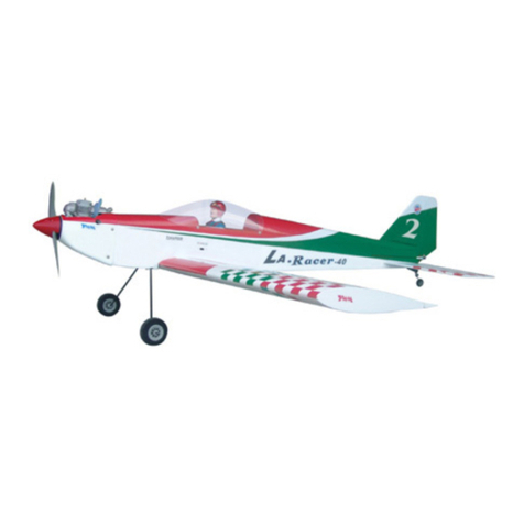
THE WORLD MODELS LA Racer-40 User manual

THE WORLD MODELS

THE WORLD MODELS LA Racer-40 User manual

THE WORLD MODELS Ultimate EP User manual

THE WORLD MODELS

THE WORLD MODELS Ultimate EP User manual

THE WORLD MODELS Spot-On 50 User manual

THE WORLD MODELS

THE WORLD MODELS Spot-On 50 User manual

THE WORLD MODELS F4U CORSAIR EP User manual

THE WORLD MODELS

THE WORLD MODELS F4U CORSAIR EP User manual

THE WORLD MODELS Zen 120 User manual

THE WORLD MODELS

THE WORLD MODELS Zen 120 User manual

THE WORLD MODELS PAULISTINHA P-56 EP User manual

THE WORLD MODELS

THE WORLD MODELS PAULISTINHA P-56 EP User manual

THE WORLD MODELS Pilatus PC-6 Porter 40 User manual

THE WORLD MODELS

THE WORLD MODELS Pilatus PC-6 Porter 40 User manual

THE WORLD MODELS P-51 MUSTANG 46 User manual

THE WORLD MODELS

THE WORLD MODELS P-51 MUSTANG 46 User manual

THE WORLD MODELS P-51 MUSTANG EP 40 User manual

THE WORLD MODELS

THE WORLD MODELS P-51 MUSTANG EP 40 User manual

THE WORLD MODELS Zero Fighter 60S User manual

THE WORLD MODELS

THE WORLD MODELS Zero Fighter 60S User manual

THE WORLD MODELS Velox REV II-60 User manual

THE WORLD MODELS

THE WORLD MODELS Velox REV II-60 User manual

THE WORLD MODELS Extra 300 EP User manual

THE WORLD MODELS

THE WORLD MODELS Extra 300 EP User manual

THE WORLD MODELS Zero Fighter 60S User manual

THE WORLD MODELS

THE WORLD MODELS Zero Fighter 60S User manual

THE WORLD MODELS A322S User manual

THE WORLD MODELS

THE WORLD MODELS A322S User manual

THE WORLD MODELS VOODOO MUSTANG EP User manual

THE WORLD MODELS

THE WORLD MODELS VOODOO MUSTANG EP User manual

THE WORLD MODELS Groovy 90 User manual

THE WORLD MODELS

THE WORLD MODELS Groovy 90 User manual

THE WORLD MODELS 1/4 SUPER CUB User manual

THE WORLD MODELS

THE WORLD MODELS 1/4 SUPER CUB User manual

THE WORLD MODELS AirMaster 5000 User manual

THE WORLD MODELS

THE WORLD MODELS AirMaster 5000 User manual

THE WORLD MODELS RAMBLER-45 User manual

THE WORLD MODELS

THE WORLD MODELS RAMBLER-45 User manual

THE WORLD MODELS Sky Runner User manual
THE WORLD MODELS

THE WORLD MODELS Sky Runner User manual

THE WORLD MODELS PIPER J-3 CUB EP User manual

THE WORLD MODELS

THE WORLD MODELS PIPER J-3 CUB EP User manual

THE WORLD MODELS 50CC SKY LINK User manual

THE WORLD MODELS

THE WORLD MODELS 50CC SKY LINK User manual

THE WORLD MODELS Wing Jet EP User manual

THE WORLD MODELS

THE WORLD MODELS Wing Jet EP User manual

THE WORLD MODELS SPITFIRE 40 User manual

THE WORLD MODELS

THE WORLD MODELS SPITFIRE 40 User manual

Popular Toy manuals by other brands
BELL HELICOPTER 430 Maintenance manual

BELL HELICOPTER

BELL HELICOPTER 430 Maintenance manual

REVELL Aces Wild Custom Chopper Assembly manual

REVELL

REVELL Aces Wild Custom Chopper Assembly manual

Schleich 42273 Assembly instruction

Schleich

Schleich 42273 Assembly instruction

RUNRIDER 700 Blue Thunder instruction manual

RUNRIDER

RUNRIDER 700 Blue Thunder instruction manual

Eduard Marder I on FCM 36 base Assembly instructions

Eduard

Eduard Marder I on FCM 36 base Assembly instructions

Eduard U-boat VIIC quick start guide

Eduard

Eduard U-boat VIIC quick start guide

Model Space D51 200 quick start guide

Model Space

Model Space D51 200 quick start guide

Eduard Fw 200 Condor interior Assembly instructions

Eduard

Eduard Fw 200 Condor interior Assembly instructions

Costway BE10002 user manual

Costway

Costway BE10002 user manual

Eduard J2M3 Raiden exterior quick start guide

Eduard

Eduard J2M3 Raiden exterior quick start guide

Fisher-Price V3711 instructions

Fisher-Price

Fisher-Price V3711 instructions

Hobbico Flyzone Sensei FS instruction manual

Hobbico

Hobbico Flyzone Sensei FS instruction manual

Sci-High viper mark II Assembly manual

Sci-High

Sci-High viper mark II Assembly manual

LEGO 76035 instructions

LEGO

LEGO 76035 instructions

Centuri 33 Technical information report

Centuri

Centuri 33 Technical information report

Lionel Extension Searchlight Car quick start guide

Lionel

Lionel Extension Searchlight Car quick start guide

Viessmann TT 6923 Operation manual

Viessmann

Viessmann TT 6923 Operation manual

Faller Butchery/Bakery Assembly instructions

Faller

Faller Butchery/Bakery Assembly instructions

manuals.online logo
manuals.online logoBrands
  • About & Mission
  • Contact us
  • Privacy Policy
  • Terms and Conditions

Copyright 2025 Manuals.Online. All Rights Reserved.