Oriental motor VEXTA BX Series User manual

HM-6168-2
This manual describes handling procedures and precautions to ensure safe
operation.
・Read the manual carefully to ensure the safe operation of the equipment.
・After reading this manual, keep it handy so that you can refer to it whenever
required.
BX Series
OPERATING MANUAL FOR
EXTENSION FUNCTIONS
AC Servo Motor

2
1. Introduction
This operation manual describes how to use the extension functions of the AC servo motor
BX series using the data setter OPX-1. Before you read this operation manual for extension
functions, read the operation manual for BX series to become thoroughly familiar with basic
operation procedures of the driver. After learning the previous information, read this manual
describing the functions to be extended by the data setter OPX-1.
Major functions to be extended by the System Upgrading Tool Data
Setter OPX-1
In addition to the speed control mode function of the main unit of the BX series driver,
the equipment provides the rotary speed digital setting function and position control
mode function.
Only the speed control mode (when you do not use the data setter
OPX-1)
Speed setting range: Analog two types 30 to 3,000r/min
Slow start time setting range: Analog 0 to 15sec.
Slowdown time setting range: Analog 0 to 15sec.
SS
SPEED
OPERATION
BXD120A-A
SD
ALARM
CN1
CN2
SENSOR
CN3
MOTOR
RG
RG
NC
NC
100-
115V
L
N
~
GFH4G5
GEARHEAD
ORIENTALMOTORCO.,LTD.MADEINJAPAN
OPERATIONAL UNIT OPX-1
MODESET
MON
IDXRETHOMEBUSYALM
VEXTA
R
PROGTEST

3
●Digital speed setting Page 13
Speed setting range: 0 to 3,000r/min
The equipment offers you a function to set motor speed in increments of 1r/min, in
addition to the analog setting function using the internal and external potentiometers of
the driver.
●Speed control mode Page 13
Provides a function to set a maximum of 8 step speed settings.
・Analog 2-step speed setting (driver) + digital 6-step setting, or
・Digital 8-step setting
●Position control mode Page 15
Provides positioning (indexing) operation with the preset motor movement, return to
mechanical home position (home operation) and return to electrical home position
(return).
Position control range: -8,388,608 to +8,388,607 steps (500 steps/rotation)
Number of index points: six
●Digital setting of slow start time and slowdown time Page 14
Slow start time setting range: 0 to 30sec.
Slowdown time setting range: 0 to 30sec.
Slow start time and slowdown time shared by both speed control mode and position
control mode can be separately set in increments of 0.001sec. directly.
●Torque limiting function Page 17
Allows a torque limit value to be set for digital and analog speed settings. You can set
the torque limit value individually for digital speed settings. The torque limit value can
be expressed in percentage based on the instantaneous maximum torque of 100%.
●Servo lock function at motor standstill (speed control mode) Page 14
Allows the use of servo lock to be selected.
●Operation monitor function Page 30
Permits the following operation items to be monitored in the monitor (MON) mode.
・Speed
・Position counter
・Torque
・Alarm code
・Alarm history (up to latest 10)
●Data copy function Page 41
Allows the data set on the data setter OPX-1 to be loaded into multiple drivers, and
enables the driver data to be saved into another data setter OPX-1.
The data setter OPX-1 has four banks as data areas to permit four types of operation
data to be stored.

4
●This product is designed to be incorporated into general industrial machinery, and must
not be used for other purposes. It should be noted that we are not responsible for any
damages caused by ignoring this warning.
●It should be noted in advance that we are not responsible for any damage or loss of
data caused by this product.
●Back up the important data to provide against a possible accident.
●No part or whole of this manual may be reproduced or copied without the prior
permission of our company. When you have damaged or lost the manual, please
contact our branch office or sales office located nearest to you, to get a new one.
●This manual is subject to change due to technological improvement of the product,
revision of the specifications or improvement of the manual itself without prior notice.
●We are making efforts to ensure that the manual carries correct information at all times.
Should you find any ambiguous statement, description error or lack of description, please
contact our sales office located nearest to you. You will find the addresses of our sales
office on the back of this manual.
The logo is based on the trademark of ORIENTAL MOTOR CO.,LTD. registered
in Japan and other countries of the world. Other product names and company names are
trade marks or registered trade marks of other companies. Other product names described
in this manual are given only for reference, and are not meant to force or recommend their
use. ORIENTAL MOTOR CO.,LTD. is not responsible for the performance of other
manufacturers products.
Copyright ORIENTAL MOTOR CO.,LTD. 2001
c

5
Table of contents
1. Introduction................................................................................................... Page 2
2. Safety Precautions ....................................................................................... Page 8
3. Preparation ...................................................................................................Page 10
3.1 Checking the product .............................................................................Page 10
3.2 Specifications.........................................................................................Page 10
4. Installation ....................................................................................................Page 11
4.1 Installation site .......................................................................................Page 11
4.2 Installation method.................................................................................Page 12
4.2.1 How to install the setter on the panel.............................................. Page 12
4.2.2 How to remove the setter from the panel........................................ Page 12
5. Overview of functions ...................................................................................Page 13
5.1 Speed control mode...............................................................................Page 13
5.1.1 Analog speed setting ...................................................................... Page 13
5.1.2 Digital speed setting........................................................................Page 13
5.1.3 Speed regulation.............................................................................Page 14
5.1.4 Slow start and slowdown time.........................................................Page 14
5.1.5 Position holding function at standstill ..............................................Page 14
5.2 Position control mode ............................................................................Page 15
5.2.1 Positioning (indexing)......................................................................Page 15
5.2.2 Return to mechanical home position (home operation) ..................Page 16
5.2.3 Return to electrical home position (return)......................................Page 16
5.2.4 Continuous operation (scan)...........................................................Page 17
5.3 Torque limiting function..........................................................................Page 17
5.3.1 Digital common torque setting ........................................................ Page 17
5.3.2 Analog common torque setting .......................................................Page 17
5.3.3 Digital independent torque setting .................................................. Page 17
6. I/O connection ..............................................................................................Page 18
6.1 List of input/output signals .....................................................................Page 18
6.2 Input signal ............................................................................................Page 19
6.3 Output signal..........................................................................................Page 24
6.4 Connection of the speed control mode ..................................................Page 26
6.5 Connection of the position control mode ...............................................Page 27

6
7. Running and parameter setting ....................................................................Page 28
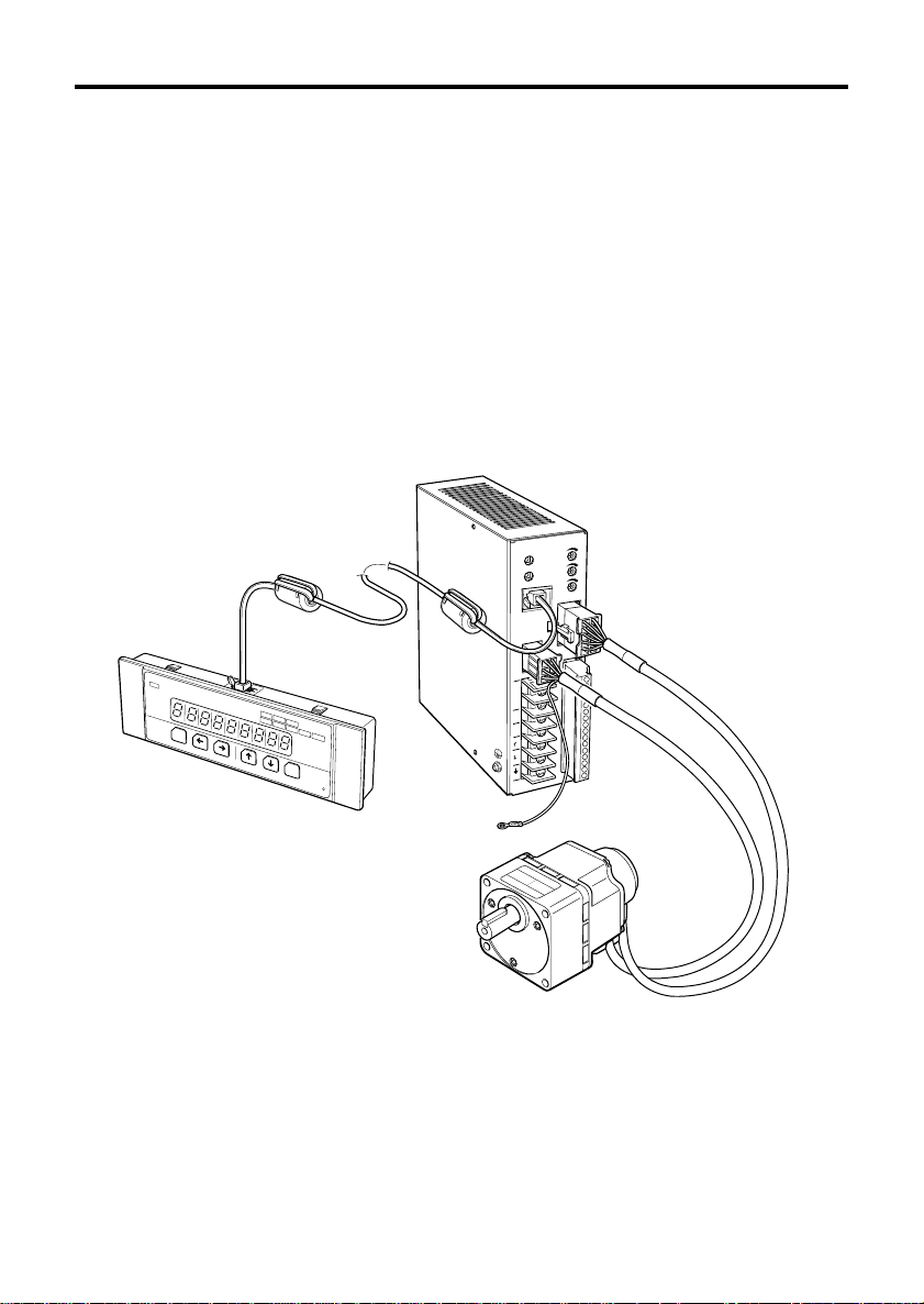
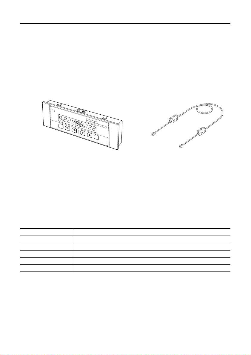
7.1 Dater setter OPX-1 ................................................................................Page 28
7.1.1 Connection......................................................................................Page 28
7.1.2 Name of individual components and function ................................. Page 29
7.1.3 LED display.....................................................................................Page 29
7.2 Data setter mode ...................................................................................Page 30
7.3 Monitor mode ......................................................................................... Page 30
7.3.1 Speed..............................................................................................Page 32
7.3.2 Position counter ..............................................................................Page 32
7.3.3 Torque.............................................................................................Page 32
7.3.4 Alarm code......................................................................................Page 32
7.3.5 Alarm history ...................................................................................Page 32
7.4 Program mode .......................................................................................Page 33
7.4.1 Selector...........................................................................................Page 34
7.4.1.1 Control mode ..........................................................................Page 35
7.4.1.2 Analog input ............................................................................Page 35
7.4.1.3 Torque limit .............................................................................Page 35
7.4.1.4 KBL-compatible mode (Enabled only in speed control mode) Page 35
7.4.1.5 Slow start and slowdown time................................................. Page 36
7.4.1.6 Output signal (BUSY/TLM) output switching........................... Page 36
7.4.1.7 Direction of return to mechanical home position..................... Page 36
7.4.1.8 Continuous operation (scan)................................................... Page 36
7.4.1.9 Initial display ...........................................................................Page 36
7.4.2 Operation data ................................................................................Page 37
7.4.2.1 Movement ...............................................................................Page 37
7.4.2.2 Rotation direction in continuous operation ..............................Page 37
7.4.2.3 Electrical home position offset ................................................Page 37
7.4.2.4 Speed of rotation..................................................................... Page 38
7.4.2.5 Torque limit .............................................................................Page 38
7.4.3 Control parameter ...........................................................................Page 39
7.4.3.1 Digital torque limit used in common ........................................Page 39
7.4.3.2 Slow start time ........................................................................Page 39
7.4.3.3 Slowdown time ........................................................................Page 39
7.4.3.4 Speed reduction ratio (for speed display) ...............................Page 39
7.4.4 Adjustment parameter.....................................................................Page 40
7.4.4.1 Position loop proportional gain................................................ Page 40
7.4.4.2 Speed loop proportional gain ..................................................Page 40
7.4.4.3 Speed loop integral gain .........................................................Page 40
7.4.4.4 Positioning completion width................................................... Page 40
7.4.5 Copy function ..................................................................................Page 41
7.4.5.1 Loading ...................................................................................Page 42
7.4.5.2 Saving .....................................................................................Page 42
7.4.5.3 Verifying ..................................................................................Page 42
7.4.5.4 Initialization .............................................................................Page 42
7.4.5.5 Cancel ..................................................................................... Page 42
7.5 Test mode .............................................................................................. Page 43
7.5.1 Jog operation preparation ...............................................................Page 43
7.5.2 Jog operation .................................................................................. Page 43

7
8. Setting example............................................................................................ Page 44
8.1 Selector..................................................................................................Page 44
8.1.1 Changing method of control mode..................................................Page 44
8.1.2 Changing method between analog speed setting and digital
speed setting (Analog input) ...........................................................Page 45
8.1.3 Selection of setting torque limit .......................................................Page 46
8.1.4 Changing method of rotation input at speed control
(KBL-compatible mode)...................................................................Page 47
8.1.5 Changing method between analog setting and digital setting of
slow start/slowdown ........................................................................Page 48
8.1.6 Changing method of BUSY signal output in the process of TLM
torque limit ...................................................................................... Page 49
8.1.7 Changing method of direction of return to mechanical home
position............................................................................................Page 50
8.2 Operation data .......................................................................................Page 51
8.3 Control parameter .................................................................................. Page 52
8.4 Adjustment parameter ...........................................................................Page 53
8.5 Copy function ......................................................................................... Page 54
8.5.1 Loading ...........................................................................................Page 54
8.5.2 Saving .............................................................................................Page 55
8.5.3 Verifying ..........................................................................................Page 56
8.5.4 Initialization .....................................................................................Page 57
8.5.5 Cancel............................................................................................. Page 58
9. Alarm display and details..............................................................................Page 59

8
Only qualified personnel should work with the product.
Before using it, carefully read theSafety precautionsto ensure correct operation.
The cautions described below are intended to ensure the correct use of the product and to
prevent the customer and other people from being injured.
And, read theSafety precautionson the BX series manual.
Warning
Failure to observe the warnings contained herein may result in a situation leading to serious
injury or death.
Caution
Failure to observe the following precautions may result in injury or property damage.
2. Safety precautions
General
●Do not use the product in an explosive, flammable, or corrosive atmosphere to avoid
possible fire, electric shock or personal injury. Do not use it where it may be splashed
with water, or near the combustible substances.
●Only qualified installers should be assigned to the work of installation, connection,
running, operation, inspection and trouble diagnosis. This is intended to prevent fire,
electric shock and injury.
●Do not move, install, connect or inspect the product when power is applied. Turn off
power before starting such work. This caution is to prevent possible electric shock.
●Immediately after the protection function has been activated, turn off the power and
remove the cause.
Then turn on power again. If the motor operation is continued without removing the
cause, the motor and driver may operate incorrectly causing personal injury and
equipment damage.
Electrical connections
●Electrical connections must be made in strict accordance with the connection diagram.
Otherwise, fire and electric shock may occur.
●Do not turn ON the FREE input when the position is held in the vertical direction.
Otherwise, the holding force of the motor and electromagnetic brake will be lost,
causing personal injury and equipment damage.
Warning
Note
The items under this heading contain important handling instructions that the user should
observe to ensure the safe use of the product.

9
Repair, disassembly and modification
●Do not disassemble or modify the data setter. Otherwise you may get an electric shock
or injury. When internal inspection and repair must be made, contact your local sales
office.
General
●Do not use the motor, gearhead and driver in excess of ratings. Otherwise, you may
get an electric shock, injury or the equipment may be damaged.
Running
●Start running after making sure that the emergency stop can be used whenever
required. Otherwise, injury may occur.
Scrapping
●When scrapping the data setter, scrap it as industrial waste.
Caution

10
3.2 Specifications
The following shows the specifications for the data setter.
For dimensions, see the catalog.
One data setter OPX-1 One data setter cable
Manual
3. Preparation
The following describes the items to be checked before operation, the names and functions
of individual components as well as the main specifications.
3.1 Checking the product
Open the package and make sure that the following items are supplied.
If there is any shortage or damage, contact the sales office where you bought the product.
Data setter OPX-1
Items Specifications
Connection Modular 4 poles
Dimensions 142 (W)×48 (H)×17 (D)mm [5.59(W)×1.89(H)×0.67(D) in.]
Mass 0.07kg (0.15lb.)
Ambient temperature 0℃to +50℃(+32°F to +122°F) (non-freezing)
Ambient humidity 85% or less (non condensing)
ORIENTALMOTORCO.,LTD.MADEINJAPAN
OPERATIONALUNIT OPX-1
MODE SET
MON
IDXRETHOMEBUSYALM
VEXTA
R
PROGTEST

11
The following shows the data setter OPX-1 installation environment, installation method
and load installation.
●Only qualified installers should be assigned to the work of installation,
connection, running, operation, inspection and trouble diagnosis. This is
intended to prevent fire, electric shock and injury.
●Do not move, install, connect or inspect the product when power is
applied. Turn off power before starting such work. This caution is to
prevent possible electric shock.
4.1 Installation site
The data setter OPX-1 is designed and manufactured to be incorporated into the
equipment.
To ensure effective ventilation and easy inspection, install it in the following site.
●In the indoor housing (where a ventilation port must be provided)
●Ambient temperature: 0℃to +50℃(+32°F to +122°F) (non-freezing)
●Ambient humidity: 85% or less (non condensing)
●Not in the explosive atmosphere with hazardous gas or liquid
●Not exposed to sunlight
●Not at the site exposed to much dust or metallic particles
●Not at the place splashed with water (rain or water drop), oil (oil drop) or other liquid
●Not at the site containing much salt
●Not subjected to continuous vibration or excessive shock
●Not at the position exposed to much electromagnetic noise (caused by welder and
power driven equipment)
●Not at the site near radiation, magnetic field or vacuum environment is designed and
manufactured to be incorporated into the equipment.
4. Installation
Warning

12
4.2 Installation method
4.2.2 How to remove the setter from the panel
Remove the modular connector from the data setter.
Note
The thickness of installation panel must not exceed 3mm (0.12in.).
If you install the data setter on the panel in excess of 3mm (0.12in.), you cannot connect the
modular connector of the connection cable.
ORIENTALMOTORCO.,LTD.MADEINJAPAN
MODESET
VEXTA
R
OPERATIONAL UNIT OPX-1
MON
IDXRETHOMEBUSYALM
PROGTEST
139+0.5 (5.4921)
05.4724
45+0.5 (1.7913)
01.7717
Simultaneously pushing in four hooks on the top and bottom of the setter from the back of
the data setter, and push it out to the front side of the panel. Then you can remove the
setter from the panel.
Note
・Do not install the equipment producing all large amount of heat and noise around the
data setter OPX-1.
・If the ambient temperature of the data setter exceeds 50℃(+122°F), re-examine the
ventilation conditions.
4.2.1 How to install the setter on the panel
As illustrated, push the data setter into the machined installation hole from the front of the
panel until you hear it click and the setter is secured in position.
[Unit: mm (inch)]

13
5. Overview of functions
The BX series provides analog input speed control as one of the major functions. Use of the
extension function permits speed control with digitally set speed, and position control with
preset motor movement.
5.1 Speed control mode
The use of the extension function of the data setter OPX-1 allows the following functions to
be added:
Digital speed setting : 0 to 3,000r/min (in increments of 1 r/min)
Speed settings in eight settings : data Nos. 0 to 7
Digital slow start/slowdown time setting : 0 to 30sec. (in increments of 0.001sec.)
Selection of servo lock for the motor at standstill
For speed selection, switch between the driver M0, M1 and M2 inputs to get the preset
data number.
Data No. M0 M1 M2 Speed
No. 0 OFF OFF OFF Analog/digital speed setting 0 selection enabled
No. 1 ON OFF OFF Analog/digital speed setting 1 selection enabled
No. 2 OFF ON OFF Digital speed setting 2
No. 3 ON ON OFF Digital speed setting 3
No. 4 OFF OFF ON Digital speed setting 4
No. 5 ON OFF ON Digital speed setting 5
No. 6 OFF ON ON Digital speed setting 6
No. 7 ON ON ON Digital speed setting 7
5.1.1 Analog speed setting
(For details, see the operating manual for AC servo motor BX series.)
Internal potentiometer : Data No. 0
External analog input : Data No. 1
・Variable resistor : 20kΩ1/4W
・0 to 5V DC (input impedance: 15kΩ)
Speed setting range : 30 to 3,000r/min.
5.1.2 Digital speed setting
Enter the speed by means of numerals using the arrow marked key of the data setter
OPX-1.
Speed setting range : 0 to 3,000r/min
Resolution : 1r/min
Initial value : 0r/min

14
5.1.3 Speed regulation
±0.05% with respect to load, 3,000r/min at rated torque time
±0.05% with respect to voltage, power supply input voltage range 3,000r/min without
load
±0.5% with respect to temperature, analog setting at ambient temperature from 0℃
(+32°F) to +50℃(+122°F), 3,000r/min without load
±0.05% with respect to temperature, digital setting at ambient temperature from 0℃
(+32°F) to +50℃(+122°F), 3,000r/min without load
5.1.4 Slow start and slowdown time
The slow start and slowdown time can be set independently of each other. The extension
function mode allows digital settings in addition to the settings on the driver. The preset slow
start and slowdown time is shared by all data number operations.
Slow start time applies to all speed change commands, for example, when data numbers
have been switched, variations of external analog input variable resistors have occurred,
and the rotation direction has been switched.
Slowdown time applies when the equipment is stopped (except for KBL-compatible mode).
0 to 15sec. (by the driver time setter in analog setting)
0 to 30sec. (in digital setting) Setting resolution: 0.001sec.
* Time denotes the time for 0 to 3,000r/min.
5.1.5 Position holding function at standstill
Selection of the data setter OPX-1 parameter allows the position holding method to be
selected when the motor is stopped.
・Motor deactivation (held by electromagnetic brake where applicable)
・Position holding by servo control (servo lock)

15
5.2 Position control mode
The following additional functions are provided if you utilize the extension function of the
data setter OPX-1.
Positioning (indexing) with either 6 or 4 different data settings
Continuous operation (scan) with up to 2 different data settings
Return to mechanical home position (home operation) by one-sensor structure
Return to electrical home position (return)
Positioning range: -8,388,608 to +8,388,607 steps
Selection among positioning data (rotation direction, position setting and speed), return to
electrical home position, and return to mechanical home position is provided by choosing
the set data number by switching among the drivers M0, M1 and M2 inputs.
5.2.1 Positioning (indexing)
The motor runs in the direction at the speed preset on the selected data number and stops
at the preset position.
Position setting method : Incremental (from the current position to relative position)
Resolution : 1 step (0.72[゚], 500[p/r])
Position control range : -8,388,608 to +8,388,607 steps (data Nos. 0 to 5)
Speed : According to speed control mode (data Nos. 0 to 5)
Slow start time : According to speed control mode
Slowdown time : According to speed control mode
Data No. M0 M1 M2 Operating mode
No. 0 OFF OFF OFF Positioning 0/Continuous 0
No. 1 ON OFF OFF Positioning 1/Continuous 1
No. 2 OFF ON OFF Positioning 2
No. 3 ON ON OFF Positioning 3
No. 4 OFF OFF ON Positioning 4
No. 5 ON OFF ON Positioning 5
No. 6 OFF ON ON Return to electrical home position
No. 7 ON ON ON Return to mechanical home position

16
5.2.2 Return to mechanical home position (home operation)
The home position is detected by the home sensor (HOME-LS input) mounted on the
equipment by running the motor in the preset detection start direction.
Stops at the position out of the home sensor range by reversing after detection of the
home sensor.
Mechanical home position detection by 1-sensor method (B contact point input)
Direction of home detection start : Settable to CW or CCW
Speed : According to speed control mode (data No. 7)
Slow start/slowdown : Not provided
5.2.3 Return to electrical home position (return)
The motor moves to the electrical home position.
After returning to the mechanical home position, the offset mechanical position serves as
an electrical home position. When the offset value of the electrical home position is zero,
the electrical home position matches the mechanical home position. The setting of offset
value enables one to use different settings for the electrical home position and mechanical
home position.
However, before returning to the mechanical home position, the position of the motor
immediately after having turned on the driver’s power supply becomes the electrical home
position.
Movement : From the motor stop position to the electrical home position
Speed : According to speed control mode (data No. 6)
Slow start time : According to speed control mode
Slowdown time : According to speed control mode
Note
Install the home sensor (HOME-LS input) just before the stroke end sensor in the direction
of starting detection.
Example of use: Return to mechanical home position using the ball screw
(2) Moves out of the sensor range to find out the home.
Home sensor Table
Motor
Sensor
detection
Sensor non-detection
Mechanical
stroke end Mechanical
stroke end
(1) Sensor detection operation

17
5.3 Torque limiting function
You can set the motor output torque limiting value similarly to the case in speed control/
position control modes.
Torque limiting values can be selected in the following three ways:
Digital common torque setting
Analog common torque setting
Digital independent torque setting (to be set together with data number)
5.3.1 Digital common torque setting
A torque limiting value can be set for all data numbers in one operation.
Assuming that instantaneous maximum torque is 100%:
Setting range : 1 to 100 [%]
Resolution : 1 [%]
5.3.2 Analog common torque setting
A torque limiting value can be set for all data numbers in one operation by means of external
analog input.
It should be noted, however, that the digital speed setting is enabled.
Setting range : 1 to 100 [%]
Analog input
Variable resistor: 20kΩ1/4W
DC voltage : 0 to 5V DC (input impedance: 15kΩ)
5.3.3 Digital independent torque setting
A torque limit can be set independently for each of data Nos. 0 to 7 by numerical entry.
Setting range : 1 to 100 [%]
Resolution : 1 [%]
5.2.4 Continuous operation (scan)
Set data Nos. 0 and 1 to continuous operation in the position control mode.
Speed : According to speed control mode
Slow start time : According to speed control mode
Slowdown time : According to speed control mode
Rotation direction : CW when the movement is set to zero or greater; CCW when the
movement is set to -1 or less.

18
6.1 List of input/output signals
By selection of the control mode (speed control and position control) and switching of the
terminal function, input/output signal functions are assigned as follows:
6. I/O connection
■Electrical specifications
Input signal
Photocoupler input
Internal voltage 15V DC
Internal resistance 2.3kΩ
External analog input
20kΩ1/4W when a variable resistor is connected
0 to 5V DC when DC power supply is connected (input impedance: 15kΩ)
Output signal
Open collector output
External pull-up voltage 4.5 to 26.4V DC
Maximum output current 40mA (ALM for terminal No. 12; BUSY/TLM/ALP for
terminal No. 13)
Maximum output current 20mA (ASG for terminal No. 14; BSG for terminal
No. 15)
Position control mode
START
HOME-LS
M0
M1
M2
FREE
BRAKE/ACL
IN-COM
H
M
L
ALM
BUSY/TLM/ALP
ASG
BSG
OUT-COM
Terminal No.
1
2
3
4
5
6
7
8
9
10
11
12
13
14
15
16
Type
Input
Common
External
analog input
Output
Common
Speed control mode
CW
CCW
KBL-compatible mode
START
DRE

19
■I/O theory
Photocoupler input/output in the timing chart are expressed in terms of ON/OFF states
(activated/not activated states) of the photocoupler. The photocoupler is ON when the
terminal voltage level is L.
6.2 Input signal
■CW (Speed control mode)
CW rotation command ON: CW rotation OFF: Stop
CCW (Speed control mode)
CCW rotation command ON: CCW rotation OFF: Stop
※The BRAKE input is OFF and the motor stops. To start the motor, be sure to select ON.
Terminal level
Photocoupler state OFF ON
H
L
CW input
BRAKE input
BUSY output
CCW input
ON ON
ON
ON ON
ON
ON
ON
−
+
Speed
Slow start
time Slowdown
time Slow start
time Slowdown
time Slow start
time
Operation signal timing chart (speed control mode)

20
■START (KBL-compatible mode)
ON: Operation OFF: Stop
DRE (KBL-compatible mode) Changing of rotation direction
ON: CW rotation OFF: CCW rotation
※The BRAKE input is OFF and the motor stops. To start the motor, be sure to select ON.
START input
BRAKE input
BUSY output
DRE input
ON ON ON
ON ON
ON
ON ON
ON
−
+
Speed
Slow start
time Slowdown
time Slow start
time Slowdown
time Instantaneous bi-directional
rotation time
Operation signal timing chart (KBL-compatible mode)
This manual suits for next models
1
Table of contents
Popular Industrial Monitor manuals by other brands

Advantech
Advantech FPM-7211W Series user manual

Rompa
Rompa snoezelen Colour Catch Combo 24511 instruction manual

Hope Industrial Systems
Hope Industrial Systems HIS-ML15-***E Series user manual

NexAIoT
NexAIoT APPD 1206T user manual

AIS
AIS CHW22L110-A3-5RT user guide

Austin Hughes
Austin Hughes CyberView RP-920 user manual