Orion Control Systems PT-Link II N2-3 Quick start guide

PT-Link II N2-3®
Technical Guide
www.orioncontrols.com
VCM-X Controller Code: SS1026 & Y200920 Version 2.0 and up;
VCM-X WSHP Controller Code: SS1032 & SS1033
SA Controller Code: Y200921
VCM Controller Code: SS1016, Y200409, Y200616, Y200822
www.orioncontrols.com
WattMaster Label
#LB102080-01
Rev. 01A
OE368-23N-N2-3
PT-LINK II PROTOCOL
TRANSLATOR
FOR N2
+24 VAC
GND
LOOP
LED 1
LED 2
= RAPID BLINK
= BLINKS QTY
CONTROLLERS
= STEADY BLINK
PROTO
TIMER
WATCH DOG
H-BEAT
= RAPID BLINK
= STEADY BLINK
= ON SOLID
= STEADY BLINK
LED BLINK CODES (NORMAL)

Table of Contents
WattMaster Controls, Inc.
8500 NW River Park Drive · Parkville, MO 64152
Toll Free Phone: 866-918-1100
PH: (816) 505-1100 · FAX: (816) 505-1101 · E-mail: mail@wattmaster.com
Visit our web site at www.orioncontrols.com
Form: OR-PTLNK3N2-TGD-01E
Copyright October 2016 WattMaster Controls, Inc.
N2®is a registered trademark of Johnson Controls, Inc.
FieldServer is a Registered Trademark of FieldServer Technologies, Milpetas, CA
Windows®XP, Vista, 7, 8 & 10 are registered trademarks of Microsoft Corporation.
WattMaster Controls, Inc. assumes no responsibility for errors, or omissions.
This document is subject to change without notice.
General Information......................................................................................................................................... 3
Hardware Specifications ..............................................................................................................................................................3
System Requirements..................................................................................................................................................................3
Dimensions and Components......................................................................................................................................................4
Quick Start Guide ............................................................................................................................................ 4
Connection and Wiring Information ................................................................................................................ 5
Configuring the PT-Link II Controller............................................................................................................... 6
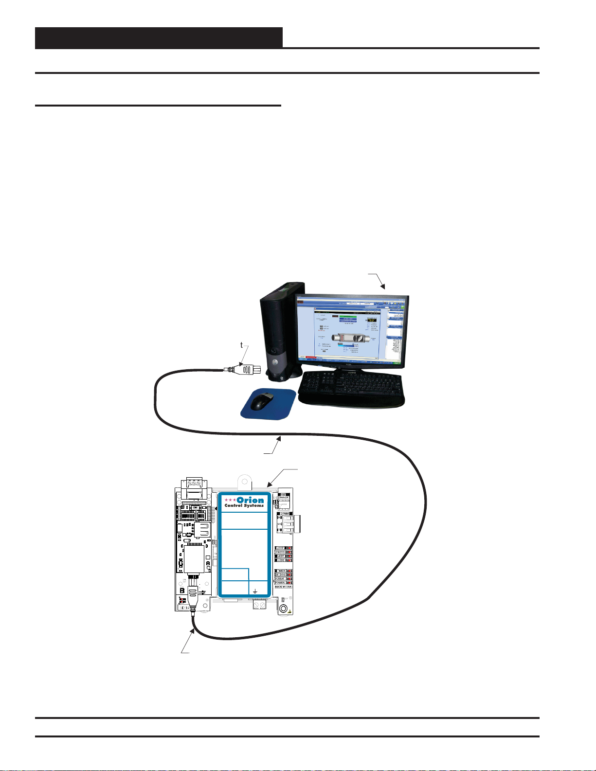
PT-Link II Hardware Connection ..................................................................................................................................................6
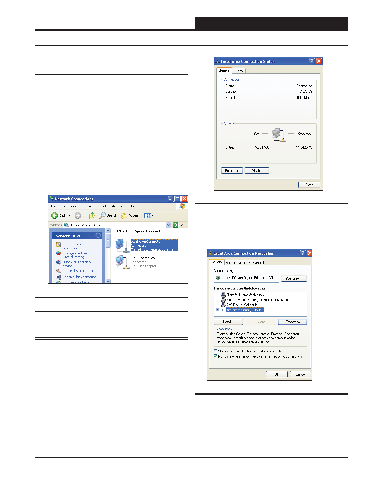
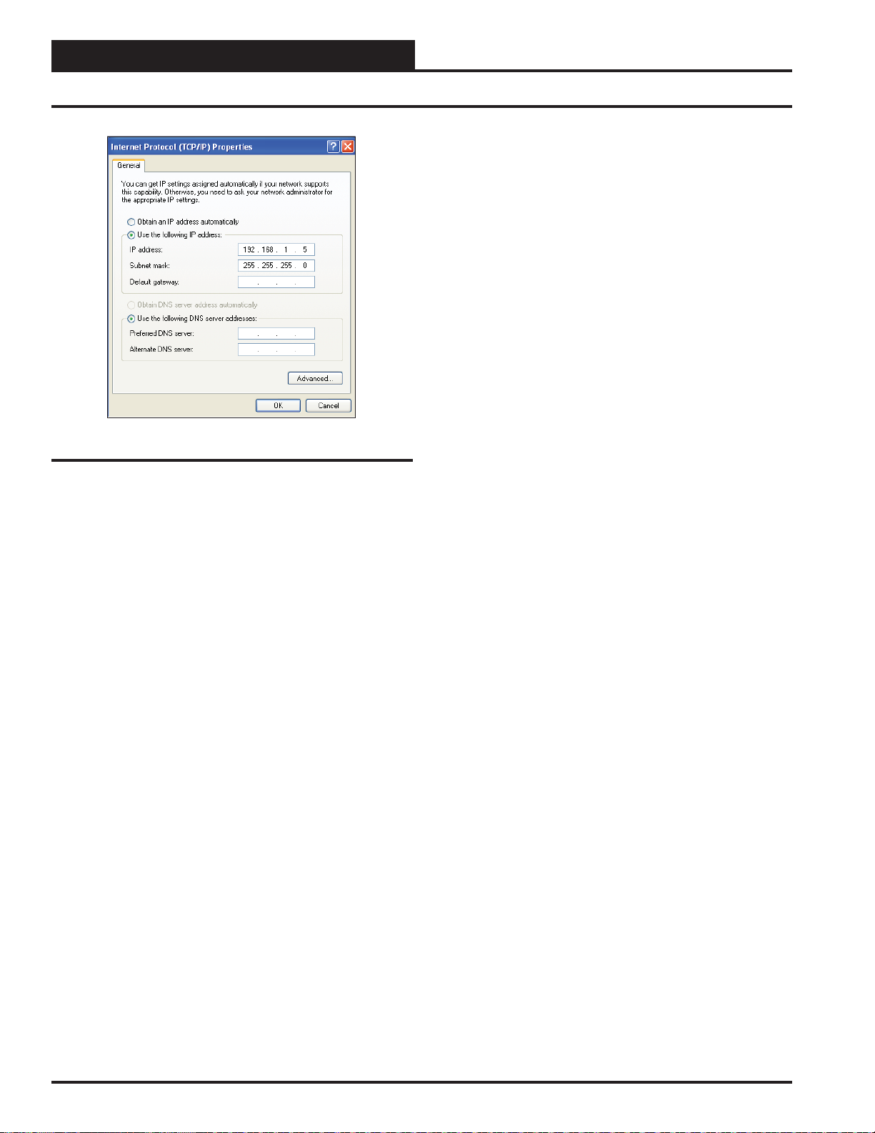
Computer IPAddress Set-up for Windows NT & XP....................................................................................................................7
Computer IPAddress Set-up for Windows Vista, 7, or 8..............................................................................................................8
Connecting to the PT-Link II using Field Server’s Graphical User Interface................................................................................9
Updating the Configuration File (config.csv) ................................................................................................................................9
Troubleshooting the PT-Link II Controller..................................................................................................... 12
Addressing WattMaster Devices in an N2®Network..................................................................................................................12
PT-Link II Board LEDs................................................................................................................................................................13
ProtoCessor Module LEDs - OE368-23N-N2-3..........................................................................................................................14
Updating the PT-Link II Controller................................................................................................................. 15
Data Arrays.................................................................................................................................................... 19
Table 2: VCM-X WSHP (Tulsa) Data Array for Field Server......................................................................................................19
Table 3: VCM-X WSHP (Coil) DataArray for Field Server........................................................................................................19
Table 4: VCM-X Data Array for Field Server..............................................................................................................................20
Table 5: SA Controller Data Array for Field Server....................................................................................................................20
Table 6: VCM Data Array For Field Server................................................................................................................................21
Appendix A - FieldServer’s Graphical User Interface Reference Guide....................................................... 22
Appendix B - VCM-X WSHP N2 Parameters................................................................................................... 25
Appendix C - VCM-X N2 Parameters ............................................................................................................. 27
Appendix D - SA Controller N2 Parameters .................................................................................................. 34
Appendix E - VCM N2 Parameters................................................................................................................. 37

PT-Link II N2-3 Interface 3
PT-Link II N2-3®Technical Guide
The OE368-23N-N2-3, PT-Link II N2-3®provides bi-directional com-
munication between your N2® MS/TPprotocol network and up to four*
of any of the following types of Orion controllers—VCM-X, SA, VCM,
MUA II, or VAV/CAV:
VCM-X Controller (SS1026, SS1032, SS1033, Y200920)
SA Controller (Y200921)
VCM Controller (SS1016, Y200409, Y200616, Y200822)
**VAV/CAV Controller (SS1003, Y200301) and
MUA II Controller (SS1004, Y200405)
To determine what controller you have, you must look at the label lo-
cated on the controller EPROM. If the controller label does not match
any of the SS or Y numbers listed above, your controller will not work
with the PT-Link II N2®.
*NOTE: ThePT-Link II N2®device can be used to connect toonly
four Orion controllers. If more than four Orion control-
lers are present in a system, you will need one or more
additional PT-Link II N2®devices for integration with
an N2®protocol network.
**NOTE: Documentation is available for MUAII/VAV/CAV on
our Orion Controls website: www.orioncontrols.com.
Data Sharing
The PT-Link II N2®interface provides the following data sharing
capabilities:
• Provides values from points on the Orion side of the
gateway to N2®devices as if the values were
originating from N2®objects.
• Allows N2®devices to modify point values on the
Orion controller side of the PT-Link II N2®by using
standard N2®write services.
Scheduling
• Ability to allow N2®devices to send Schedule events
to the Orion controller side of the gateway by using
standard N2®services.
Hardware Specifications
Table 1 contains the hardware specifications for the PT-Link II N2®
interface.
Technical Data
N2®-MS/TP Loop 9600 Mbps
Controller Loop RS-485, 9600 Baud Rate
Protocol (N2®Loop) Metasys®N2 Open
Protocol
(WattMaster Loop) HSI Open Protocol Token Passing
Power Input Voltage 24 VAC
Power Consumption 10 VA Maximum
Operating Temp -30°F to 150°F
Operating Humidity 90% RH Non-Condensing
Weight 4.5 oz.
Device Type External Vendor Device
Table 1: PT-Link II N2®Interface Technical Data
System Requirements
• The PT-Link II N2®interface is packaged and assembled
as surface mount. Surface mount components are included
for your convenience.
• Computer running Microsoft WindowsTM operating
system.
• Ethernet Crossover Cable (supplied).
• PT-Link II N2 software—located on included CD-ROM
and downloadable from www.orioncontrols.com.
• RUINET software—located on included CD-ROM and
downloadable from www.orioncontrols.com. The software
is not necessary for the initial setup.
• Prism 2 software—downloadable from
www.orioncontrols.com.
General Information

PT-Link II N2-3®Technical Guide
PT-Link II N2-3 Interface
4
Setting Up Your PT-Link
Figure 1: PT-Link II N2®Dimensions and Components
485
DRIVER
COMM
R
SH
T
LOOP
PROTO
LED1
LED2
TIMER
W_DOG
H-BEAT
POWER
MADE IN USA
4.82
4.70
0.27
4.31
1.31
2.61
4.25
2.37
N2®
Communications
Wiring Terminal
N2®
Protocessor
Module
Ethernet
Port
0.20 Dia.
Mounting Hole
Typ. 4 PL.
Local Loop
Communications
Wiring Terminal
Local Loop
Communications
Driver Chip
24 VAC Power
Terminal
Communications
LED
Diagnostic
LED #1
Diagnostic
LED #2
Power
LED
USB
Port
Configuration
DIP Switches
(Not Used)
IAEZH004
Made in USA
1
2
3
4
5
6
7
8
O
N
O
N
1
2
3
4
ON
RSGND
www.orioncontrols.com
WattMaster Label
#LB102080-01
Rev. 01A
OE368-23N-N2-3
PT-LINK II PROTOCOL
TRANSLATOR
FOR N2
+24 VAC
GND
LOOP
LED 1
LED 2
=RAPID BLINK
=BLINKS QTY
CONTROLLERS
=STEADYBLINK
PROTO
TIMER
WATCH DOG
H-BEAT
=RAPID BLINK
=STEADYBLINK
= ON SOLID
=STEADYBLINK
LED BLINK CODES (NORMAL)
Quick Start Guide
The following steps will get you up and running in no time:
1. Familiarize yourself with the PT-Link II components (Figure 1).
NOTE: The DIP Switches should be left in their default positon
which is all OFF. They are not used in this application.
2. Connect your PT-Link II to the Controller(s) on your system
(up to four) and connect your PT-Link II to the N2-3 Network
(Figure 2).
3. Copy the contents of the PT Link II CD to your PC’s Desktop.
You can also download the files from orioncontrols.com
under PT-Link II Setup Files. These files include RUINET.
4. Connect your PT-Link II to your computer using an Ethernet
connection (Figure 3, page 6).
5. Change your PCs IPAddress. Follow the directions that match
your current operating system - Windows XP, Vista, 7, 8 or 10.
See directions on pages 7 & 8.
6. Obtain the following from your Building Automation System
Integrator: the N2-3 Device Instant Number (Client Node ID).
7. Using FieldServer’s Graphical User Interface, edit the
Config.csv file and verify PT Link II communications.
Follow the directions on pages 9-11.
8. If you run into any problems, follow the instructions in the
Troubleshooting section starting on page 12 of this guide.

PT-Link II N2-3 Interface
PT-Link II N2-3®Technical Guide
5
Connection and Wiring Information
Figure 2: PT-Link II N2®Interface Wiring
Modular Service Tool
Mode
Selection
ENTER
CLEAR
ESC
PREV NEXT
DOWN
UP
6
5
4
DEC
7
0
8
13
2
9
MINUS
-
STATUS
SETPOINTS
SCHEDULES
CONFIGURATION
ALARMS
ON
OVERRIDES
BALANCE- TEST
Up To 4 Controllers
Can Be Interconnected.
Controller’s Address
Cannot Be Higher Than 16.
Note: All Programming Of
Controllers Must Be Done
Using The Modular Service
Tool. The Modular System
Manager Should Not Be Used
On A System That Has A
PT-Link Installed.
Caution: The
Communication Terminal Block
Must Be Disconnected Before
Connecting The Modular Service
Tool. After Programming The
Controller(s), Disconnect The
Service Tool and Then Reconnect
The Communication Terminal
Block.
Metasys N2
®®
Line Voltage
24 VAC
(8 VA)
Line Voltage
24 VAC
(8 VA)
Line Voltage
Controller
Controller
Controller
Controller
24 VAC
(8 VA)
Line Voltage
24 VAC
(8 VA)
SHLD
T
R
Typical Terminal Blocks. All
Wiring To Be T To T, SHLD
(G) To SHLD (G) & R To R
+
-
G
Wiring Notes:
1.) All wiring to be in accordance with local and national
electrical codes and specifications.
2.) All communication wiring to be 18 gauge minimum, 2
conductor twisted pair with shield. Use Belden #82760 or
equivalent.
Line Voltage
24 VAC
(10 VA)
PT- Link- N2 Interface
®
Metasys N2 Open
Communications
Wiring Terminals
®®
Metasys N2 Open
Communications
Wiring Terminals
®®
IMPORTANT WIRING NOTE:
Use the Daisy-Chain Topology As Shown in This Diagram.
DO NOT Use a Star Topology with Multiple Units Tied
Directly to the PT-Link II.
1
2
3
4
5
6
7
8
O
N
O
N
1
2
3
4
ON
RSGND
www.orioncontrols.com
WattMaster Label
#LB102080-01
Rev. 01A
OE368-23N-N2-3
PT-LINK II PROTOCOL
TRANSLATOR
FOR N2
+24 VAC
GND
LOOP
LED 1
LED 2
=RAPID BLINK
=BLINKS QTY
CONTROLLERS
=STEADYBLINK
PROTO
TIMER
WATCH DOG
H-BEAT
=RAPID BLINK
=STEADYBLINK
= ON SOLID
= STEADY BLINK
LED BLINK CODES (NORMAL)

PT-Link II N2-3®Technical Guide
PT-Link II N2-3 Interface
6
PT-Link II Hardware Connection
1.) Connect the PT-Link II directly to your PC by using a
standard CAT5 or crossover cable (by others) as
shown. See Figure 3 for details.
2.) Locate a CAT5 cable and plug one end into your computer’s
Ethernet port. Plug the other end of the Cable into the
Ethernet port on the PT-Link II.
3.) Power up the PT-Link II by plugging in the power cable.
The PT-Link II may take up to three minutes to power up
completely. Once the PT-Link II is powered up, you should
notice that the RUN LED is blinking continuously on the
ProtoCessor Board. See Figure 17, page 14 for a diagram
showing the location of the ProtoCessor RUN LED.
Ethernet Crossover Cable
Connect Ethernet
Crossover Cable Directly
To PC Ethernet Card Port
Connect Ethernet
Crossover Cable
To PT-Link Ethernet
Port
PT-Link N2
1
2
3
4
5
6
7
8
O
N
O
N
1
2
3
4
ON
RSGND
5308
1210
5308
IAEZH004
Made in USA
Computer
www.orioncontrols.com
WattMaster Label
#LB102080-01
Rev. 01A
OE368-23N-N2-3
PT-LINK II PROTOCOL
TRANSLATOR
FOR N2
+24 VAC
GND
LOOP
LED 1
LED 2
=RAPID BLINK
=BLINKS QTY
CONTROLLERS
=STEADYBLINK
PROTO
TIMER
WATCH DOG
H-BEAT
=RAPID BLINK
=STEADYBLINK
= ON SOLID
= STEADY BLINK
LED BLINK CODES (NORMAL)
Figure 3: Connecting With Crossover Cable
PT-Link II Ethernet Connection

PT-Link II N2-3 Interface
PT-Link II N2-3®Technical Guide
7
4.) As shown in Figure 5, click <Properties> in the lower
left of the window. The Local Area Connection Properties
Window will appear.
5). As shown in Figure 6, in the Connection Items list box,
be sure the Internet Protocol (TCP/IP) is checked. Select the
Internet Protocol (TCP/IP) item to highlight it and then click
<Properties>. The Internet Protocol Properties Window will
appear.
IP Address Configuration
Computer IP Address Set-up for Windows
XP
1.) Click <start>; then click <Control Panel>.
2.) Double-click on the Network Connections icon.
The Network Connections Window will appear (Figure 4).
NOTE: If any wireless connections are listed, disable them
by right-clicking the connection and selecting
<Disable>.
3.) In the Network Connections Window, double-click the
Local Area Connections entry. The Local Area Connection
Status Window will appear (Figure 5).
Figure 5: Local Area Connection Status Window
Figure 6: Local Area Connection Properties Window
Computer IP Address Set-up for
Windows XP, Vista, 7, 8 & 10
In order for the PT-Link II to communicate properly, it is imperative to
set the IP address of both the PT-Link II as well as the computer to be
within the same netmask. You need to change the IP address on your
computer.The following instructions will explainhow toconfigurethe IP
address for Microsoft®Windows XP,Vista, 7, 8 & 10 operating systems.
Figure 4: Network Connections Window

PT-Link II N2-3®Technical Guide
PT-Link II N2-3 Interface
8
Figure 7: Internet Protocol Properties Window
6). Select the radio button in front of Use the following
IP address (Figure 7) and write down the current defaults
so that you can re-enter them when you finish configuring
the PT-Link II and then type in the following
information:
a.) IP address 192.168.1.5
b.) Subnet mask 255.255.255.0
c.) Default Gateway is blank
7.) Click <OK> until all of the above network configuration
windows are closed. You may have to reboot the computer
before the new values are valid.
IP Address Configuration
Computer IP Address Set-up for
Windows Vista, 7, 8 & 10
1.) Click <start>; then click <Control Panel> (Vista &
Windows 7). Click <start>; then right-click for <All apps>.
Click <All apps> and then click <Control Panel>
(Windows 8).
2.) Click on the Network and Internet icon.
3.) Click Network and Sharing Center.
4.) From the shaded box in the left side of the window, select
Manage Network Connections (Vista) or Change adapter
settings (Windows 7 & 8).
5.) Right-click on the Local Area Connection icon and select
<Properties> for the drop down window.
6.) Choose Internet Protocol Version 4 (TCP/IPv4) by
highlighting it and then click <Properties>. The Internet Pro-
tocol Properties Window will appear (Figure 7).
7.) Select the radio button in front of Use the following
IP address (Figure 7) and write down the current defaults
so that you can re-enter them when you finish configuring
the PT-Link II and then type in the following
information:
a.) IP address 192.168.1.5
b.) Subnet mask 255.255.255.0
c.) Default Gateway is blank
8.) Click <OK> until all of the above network configuration
windows are closed. You may have to reboot the computer
before the new values are valid.

PT-Link II N2-3 Interface
PT-Link II N2-3®Technical Guide
9
Overview
The Field Server Graphic User Interface (FS-GUI) is a password pro-
etcted web browser-based interface that uses a combination of technolo-
gies and devices to provide a platform from which you can use to gather
and process information. The FS-GUI allows you to do the following:
• Check the status and diagnostics of the PT-Link, such as
network settings, connection information, node information,
map descriptors, and error messages
• Monitor the PT-Link’s internal data and parameters
• Change or update the PT-Link’s internal data and
parameters
• Transfer files to and from the PT-Link
• Delete files on the PT-Link
• Change the PT-Link’s IP address
• Restart the PT-Link
Hardware and Software
The following items are needed to be able to run the FS-GUI:
• PC Requirements—a computer with a web browser that
connects over the Ethernet on port 80*
*NOTE: Computer and network firewalls must be
opened for Port 80 to allow the FS-GUI to function.
• Software Requirements—Mozilla Firefox 13.0 and up,
Microsoft Internet Explorer 8 & 9**, Google Chrome 19.0
and up, Opera 11 and up, and Safari 4.1 and up
**NOTE: Internet Explorer 8 does have some limitations
in terms of graphical features. Some effects such as rounded
corners and semi-opaque backgrounds are not supported.
So, although technical functionality is operational, the looks
might be slightly different
FS-GUI Reference Guide
An FS-GUI Reference Guide can be found in AppendixA, page 22.
FS-GUI Overview and Config.csv File
Figure 8: The FS-GUI Main Screen
Changing the Config.csv File
NOTE: You may need Administration rights to perform this
function. See the Password Section on page 23.
1.) Open your web browser, and type the IP Address of the PT-Link,
which is <192.168.1.24>, and press <ENTER>.The FS-GUI will
launch. See Figure 8.
2.) In the Navigation Window on the left of the FS-GUI Screen, click
<Setup> and then click <File Transfer>. See Figure 9.
Figure 9: Navigation Window - File Transfer

PT-Link II N2-3®Technical Guide
PT-Link II N2-3 Interface
10
3.) Refer to the File Transfer Window below (Figure 10). In the Con-
figuration Tab, under Retrieve, click the config.csv file in order to save
it to a destination and then open it.
Figure 10: File Transfer - Configuration Tab
Changing the Config.csv File
4.) Open the config.csv file in Notepad. See Figure 11.
WARNING: Only edit the config.csv file using Notepad. DO
NOT use Excel. Using Excel to edit the config.csv file will
corrupt its contents!
Figure 11: Config.csv File
5.) Another change you may need to make is the Node_ID under ‘Client
Side Nodes’ which is the N2-3 Device Instance Number (Figure 12)
The default is 1.You can obtain the Node ID from your BAS Integrator.
Figure 12: Client Node ID
6.) Once all changes have been made to the text file, while still in
Notepad, click <File> in the upper left and then click <Save>. Now
close the file and return to the FS-GUI Screen open in your browser.
NOTE: Do not rename the file. The file must always be named
“config.csv”; otherwise, it will be ignored by the PT-
Link.
7.) In the File Transfer Window under Update Configuration, click
<Choose Files> or <Browse> and locate the config.csv file you just
saved. Then click <Submit>. See Figure 13. Wait until the message,
“Configuration update complete” appears and then click the <System
Restart> button at the bottom of the File Transfer Window to activate
the new configuration file.
Figure 13: Update Configuration

PT-Link II N2-3 Interface
PT-Link II N2-3®Technical Guide
11
FS-GUI File Transfers and Data Arrays
NOTE: Thefollowingfilescan also be udpated in File Transfer Window:
Firmware Files: The FieldServer Firmware contains the application
program commonly referred to as the DCC or the PCC. This program
contains the protocol drivers applicable to the application and the Field-
Server Operating System Kernel. A Firmware update is only required
when updated files are received from FieldServer support. Firmware
files have a *.bin extension. The procedure for updating these is the
same as for the configuration files, but the update needs to be made in
the Firmware Tab.
General (Other) Files: Other files that can be updated include the FS-
GUIimage andother files described indriver manuals.Theprocedure for
updating these is the same as for the configuration files, but the update
needs to be made in the General Tab.
Figure 14: Navigation Window - View Data Arrays
Verifying Communications
1. ) In the Navigation Window on the left of the FS-GUI Main Screen,
click <View> and then click <Data Arrays>. See Figure 14.
2. ) Click on the Controller name. In this case, it is DA_C160_I0, a
VCM-X Controller. The Controller’s Data Array Table will display.
See Figure 15.
Figure 15: VCM-X Data Array Table
3 ) You can now cross reference the values shown in Figure 15 with
the listed parameter names in the appropriate DataArrayTable for your
controller type. These tables can be found on pages 19-21.

PT-Link II N2-3®Technical Guide
PT-Link II N2-3 Interface
12
Troubleshooting the PT-Link II N2
Addressing WattMaster Devices in an
N2®Network.
Each PT-Link II N2®has the ability to generate virtual devices for all
of the WattMaster controls connected to it. Each virtual device operates
as an independent device and has all of the parameters pertinent to its
kind of control—VCM,VAV/CAV, or MUAII. The address of the virtual
device is calculated using the following formula:
VirtualDeviceAddress= [unit address (address set using DIP switches
on WattMaster controls) + Node_ID (value in the PT-Link II N2®
configuration file) - 1]. Example:
1.) The PT-Link II N2®has a Node_ID equal to five.
2.) Two WattMaster controls connected and addressed to one
and four.
3.) The N2®client will see two devices—one will be device
five and the other will be device eight.
Virtual N2 Device Address Example Calculation
AHU Controller Address 14
Node_ID + 55
--1 -1
Virtual N2 Device Address = 58
NOTE: To simplify the calculation, we recommend that the Watt-
Master controls be addressed in sequential order from
one to the last control without any unused address(es) in
between.

PT-Link II N2-3 Interface
PT-Link II N2-3®Technical Guide
13
PT-Link II Board LEDs
The PT-Link II N2®is equipped with LEDs that can be used for trouble-
shooting. There are eight LEDs on the PT-Link II board. See Figure 16
for the locations of the LEDs on the PT-Link II board. The LED descrip-
tions and functions are listed in the following paragraphs.
POWER LED
When the PT-Link II N2®is powered up, the “POWER” LED should
light up and stay on continuously. If it does not light up, check to be sure
that you have 24 VAC connected to the board, that the wiring connec-
tions are tight, and that they are wired for correct polarity. The 24 VAC
power must be connected so that all ground wires remain common. If
after making all these checks the “POWER” LED still does not light
up, please contact WattMaster Controls Technical Support at our Toll
Free number—866-918-1100—for assistance.
LOOP LED
When power is applied to the PT-Link II N2®, the “LOOP” LED will
also light up. The LED should flicker rapidly, indicating that the PT-Link
II is trying to communicate with the controllers on the loop.A“flicker”
is defined as a brief moment when the LED turns off and back on. If the
“LOOP” LED does not operate as indicated above, first power down
the unit and then reapply power. If this does not work, please contact
WattMaster Controls Technical Support at our Toll Free number—866-
918-1100—for assistance.
LED 1
When power is first applied, “LED 1” will be off temporarily and then
will blink one time for each controller it is communicating with. For
example, if you have 4 controllers on the loop connected to the PT-Link,
“LED 1” will blink 4 times. If the amount of blinks does not match
the number of controllers connected to the loop, it indicates there is a
communications problem. The best way to find out which board is not
communicating is to go to each controller and look at its “COMM”
LED. The “COMM” LED should be solid and will flicker occasionally
indicating communication with the PT-Link II N2®. If the “COMM”
LED does not flicker, there is no communication with that controller.
LED 2
When power is first applied, “LED 2” will be off temporarily and then
willblink slowlyindicating thatthe PT-LinkII baseboardis communicat-
ing with the Protocessor Module. If “LED 2” does not blink, check that
the Protocessor Module isinstalled correctly onthe PT-Link II baseboard
and that the “PWR” LED is lit up on the Protocessor Module.
PROTO LED
Whenthe PT-Link II isfirst powered up, the “PROTO” LEDshould light
up and stay on continuously. If the LED doesn’t light up, check that the
Protocessoris installedcorrectly andfirmly connected to the BaseBoard.
The “PWR” LED should also be lit on the Protocessor Module.
TIMER LED
The “TIMER” is used for troubleshooting by WattMaster Controls
Technical Support. The “TIMER” LED should always have a steady
blink.
Troubleshooting the PT-Link II Controller
Figure 16: PT-Link II N2® LED Locations
WATCH DOG LED
The“W-DOG”LED is usedfor troubleshooting byWattMaster Controls
Technical Support. The “W-DOG” LED should always be on solid.
HEARTBEAT LED
The “H-BEAT” LED blinks to show there is communication between
the controllers and the PT-Link. If the LED doesn’t light up, and all other
checks have been made, please contact WattMaster Controls Technical
Support at our Toll Free number—866-918-1100—for assistance.

PT-Link II N2-3®Technical Guide
PT-Link II N2-3 Interface
14
Troubleshooting the PT-Link II Controller - OE368-23N-N2-3
Figure 17: PT-Link II N2-3® LED Locations
ProtoCessor Module LEDs
Refer to Figure 17 for LED locations.
PWR LED
When the PT-Link II is first powered up, the “PWR” green LED should
light up and stay on continuously. If the LED doesn’t light up, check
that the ProtoCessor is installed correctly and firmly connected to the
Base Board.
RUN LED
Upon powerup, the “RUN” LED should light up and stay solid for 15
seconds. It should then blink steadily, signifying normal operation. The
Protocessorwill beable to access RUINETonce this LED starts flashing.
RX & TX LEDs
During normal operation, the “RX” LED will flash when a message is
received on the field port of the ProtoCessor and the “TX” LED will
flash when a message is sent on the field port of the ProtoCessor The
“TX” and “RX” LEDs work together to indicate that communication
is being established with the desired protocol network. If both LEDs
are blinking, then communication is working properly. If not, check
the protocol network wiring and the baud rate in the configuration file.
RUN2 LED
The “RUN2” LED should blink steadily after power up, signifying
normal operation. The Protocessor will be able to access RUINETonce
this LED starts flashing.
SYS ERR LED
The “SYS ERR” LED will go on solid 15 seconds after power up and
then shut off.Asteady red light will indicate there is a system error on
the ProtoCessor. If this occurs, immediately report the related “system
error” shown in the error screen of the Remote User Interface to Field-
Server Technologies for evaluation.
NODE OFFLINE LED
The “NODE OFFLINE” amber LED will go on solid 15 seconds after
power up and then shut off. Asteady amber light indicates the ProtoCes-
sor is not communicating with a device that it is polling.
NOTE: Ifallof these testsare madeand thecontroller still doesn’t
operate, please contact WattMaster Controls Technical
Support at our Toll Free number—866-918-1100—for
assistance.
Figure 18: PT-Link II N2-3® Protocessor Components

PT-Link II N2-3 Interface
PT-Link II N2-3®Technical Guide
15
Programming the PT-Link II with
BootLoader
The PT-Link II is equipped with the ability to update its software with
the use of a computer. You will need the following before you begin:
• PT-Link II in need of an update (powered up,
no other connections necessary)
• Computer running Microsoft WindowsTM operating
system
•Prism 2 software from www.orioncontrols.com
• Latest version of PT-Link II software (e-mailed from our
tech support staff or downloaded from any of our websites)
and software sheet
•USB Driver Setup.exe file located on the PT-Link II CD or
downloaded from any of our websites
•USB cable
Follow these simple steps to update the PT-Link II:
1.) Turn on your computer and download the latest Prism 2 software
from www.orioncontrols.com.
2.) Either download the PT-Link II update file from http://techsupport.
wattmaster.com or save the file to your computer from the e-mail you
received from Tech Support. Record the path and name of the file for
later use. Also, print the software sheet provided for future reference.
3.) Run the USB Driver Setup.exe file located on the PT-Link II CD or
downloaded from any of our websites so that Prism can communicate
to the PT Link II. Unzip the file to the directory where you saved your
PT-Link II software.
4.) Plug the USB cable into the computer’s and PT-Link II’s USB
ports.
5.) A message will pop-up from the lower menu bar of Windows that
reads, “Found New Hardware.” Click on this message and follow the
instructions that appear to install the USB drivers.
6.) Open Prism 2 and Login with the User Name, admin and the
Password, admin. If successful, “AdministratorAccess” will appear at
the lower right of the Prism program. NOTE: If using a Prism 2 version
prior to 4.0, the Login is flash. If successful, “Level 4Access” will ap-
pear at the lower right of the Prism program.
7.) Click on the <Job-Site> icon. The Job-Sites Window will appear.
In the Type of CommLink Dialog Box,select “Hi Speed CommLink.”
8.) In the Job-Sites Window, from the Serial Port drop down list, select
the correct COM port. If you don’t know the COM port number or if the
number is 10 or higher, follow the directions on pages 17-18.
9.) From Prism 2’s Communications tab, select “Flash Selected
Controller.”
10.) The Flash Controller Window will appear.
11.) From the Flash Controller Window’s Connection tab, select
“Direct”. Keep the Flash Controller Window open.
12.) Cycle power to the PT-Link II and within 5 seconds, click the
<Get Info> button in the Flash Controller Window. The PT-Link II in-
formation will now appear in the window under the <Get Info> button.
Updating the PT-Link II Controller

PT-Link II N2-3®Technical Guide
PT-Link II N2-3 Interface
16
Updating the PT-Link II Controller
13.) TheApplication ID should be SS1035 and theApplicationVersion
should match the software version you will be updating to.
14.) In the HEX File field, enter the path and name of the HEX file you
downloaded and/or copied to your hard drive. Use the Browse button
(...) to the right of the field if you need help in locating the file.
15.) Now, cycle power to the PT-Link II once again and within 5
seconds click on the <Program HEX> button (shown above). If suc-
cessful, you should see the Progress Application HEX bar showing the
progress percentage.
16.) When the bar shows 100% completed, verify the PT-Link II’s
software is running by observing the Timer LED blinking.
17.) Verify the PT-Link II’sApplication Version by once again cycling
power to the PT-Link II and within 5 seconds clicking the <Get Info>
button.
18.) Verify all fields are correct in the information below the <Get
Info> button and under “Finalization Data.” The “Int Flash Length”
and “Checksum” values should match the values provided with the
software sheet.

PT-Link II N2-3 Interface
PT-Link II N2-3®Technical Guide
17
Updating the PT-Link II Controller
Finding What COM Port Number the
PT-Link II is Using
1. Left-click on <Start>, located on the bottom
left of the Windows Tool Bar.
2. Select <Control Panel>.
3. Double-click the System Icon.
4. Click the <Hardware> tab.
5. Click the <Device Manager> button.
6. Click on the plus sign next to Ports to see all of the
common ports.
7. Locate the USB Serial Port (COM#). The COM# in
parentheses is the port it is located on. Write this COM
port number down. You will need to know this when
setting up the Prism software.
8. If the COM port number is 10 or greater, go to
“Changing the USB COM Port Number” on page 18.

PT-Link II N2-3®Technical Guide
PT-Link II N2-3 Interface
18
Updating the PT-Link II Controller
4. To assign a port number less than 10, click on
<Advanced>. The Advanced Settings Window
will appear.
5. In the COM Port Number drop box, select which
COM port you wish to use. Make sure you select a
COM port number that is not currently in use (you can
see the ports in use in the Device Manager Window).
Select a port that is less than 10.
NOTE: Windows®will assign a port number to every device that
has ever been installed on your computer. So if there are
no available ports below 10, choose a port number less
than 10 for a device listed that you know you are not
currently using.
6. Once you select the correct COM port number, click
<OK> and close any windows opened in the process
of changing the port number. Make note of this number
because you will need it for your Prism setup.
Changing the USB COM Port Number
When the CommLink is first plugged in, it will be assigned a COM port
number to be used for communicating with the Prism software. If the
port number is 10 or greater, it needs to be changed to a value less than
10 to be recognized by Prism.
1. Click <Start>, click <Control Panel>, click
<System>, click the <Hardware> tab, and then
click <Device Manager> to get to the Device
Manager Window.
2. Click on the plus sign next to Ports to see all of the
COM ports.
3. Right-click on “USB Serial Port (COM#)” and select
<Properties>. In the Properties Window, select the
<Port Settings> tab.

PT-Link II N2-3 Interface
PT-Link II N2-3®Technical Guide
19
VCM-X WSHP Tulsa & Coil Data Arrays
Table 2: VCM-X WSHP (Tulsa) Data Array For Field Server
Table 3: VCM-X WSHP (Coil) Data Array For Field Server
VCM-X WSHP (Tulsa) Data Array For Field Server
Offset 0 1 2 3 4 5 6 7 8 9
0AppVer ClSt HtSt OaWtbl TpDmnd SpcTp SaTp RaTp OaTp DuctPr
10 OaRh UnitMode CtrlSts ClEnbl HtEnbl EcoEnbl FanDly PofCfg CO2Cfg MdHt2Ins
20 Rt2Ins OnRlys ExRlys12 ExRlys34 EcoPos VfdBwPos VfdExPos AlmSts AlmGrp1 AlmGrp2
30 AlmGrp3 SaTpAlm OaTpAlm SpcTpAlm MchClAlm MchHtAlm PofAlm DrtFAlm SmokeAlm LoSaAlm
40 HiSaAlm CtrlTpCF CtrlTpHF CtrlTp InRh InRhStM DptStM MdClPos MdHtPos MdHt2Pos
50 Rt2Pos OcpClSt OcpHtSt UnClOst UnHtOst WtblSt SaClSt SaHtSt WmupSt SpcTpOst
60 SaTpOst RaTpOst OaTpOst CoilTpSt DptSt InRhSt DuctPrSt RfPrSt SchdFrc OnRly1
70 OnRly2 OnRly3 OnRly4 OnRly5 ExRly1 ExRly2 ExRly3 ExRly4 ExRly5 ExRly6
80 ExRly7 ExRly8 ExRly9 ExRly10 ExRly11 ExRly12 ExRly13 ExRly14 ExRly15 ExRly16
90 CO2St MinEcoSt CO2Level ByPasDmp RaDmp RfPr OaDwpt CoilTp SaTpStM PreHtSp
100 OaCFM EtCFM SaCFM OACfmSt OACfmRs OACfmStM MdCmp2 HdPr1 HdPr2 CdFan1
110 CdFan2 WaterTpA WaterTpB A1LSPAlm A1LktAlm A2LSPAlm A2LktAlm B1LSPAlm B1LktAlm B2LSPAlm
120 B2LktAlm LWT1Alm LWT2Alm POWF1Alm POWF2Alm ComMAlm RmVFDPos – – –
VCM-X WSHP (Coil) Data Array For Field Server
Offset 0 1 2 3 4 5 6 7 8 9
0AppVer ClSt HtSt OaWtbl TpDmnd SpcTp SaTp RaTp OaTp DuctPr
10 OaRh UnitMode CtrlSts ClEnbl HtEnbl EcoEnbl FanDly PofCfg CO2Cfg MdHt2Ins
20 Rt2Ins OnRlys ExRlys12 ExRlys34 EcoPos VfdBwPos VfdExPos AlmSts AlmGrp1 AlmGrp2
30 AlmGrp3 SaTpAlm OaTpAlm SpcTpAlm MchClAlm MchHtAlm PofAlm DrtFAlm SmokeAlm LoSaAlm
40 HiSaAlm CtrlTpCF CtrlTpHF CtrlTp InRh InRhStM DptStM MdClPos MdHtPos MdHt2Pos
50 Rt2Pos OcpClSt OcpHtSt UnClOst UnHtOst WtblSt SaClSt SaHtSt WmupSt SpcTpOst
60 SaTpOst RaTpOst OaTpOst CoilTpSt DptSt InRhSt DuctPrSt RfPrSt SchdFrc OnRly1
70 OnRly2 OnRly3 OnRly4 OnRly5 ExRly1 ExRly2 ExRly3 ExRly4 ExRly5 ExRly6
80 ExRly7 ExRly8 ExRly9 ExRly10 ExRly11 ExRly12 ExRly13 ExRly14 ExRly15 ExRly16
90 CO2St MinEcoSt CO2Level ByPasDmp RaDmp RfPr OaDwpt CoilTp SaTpStM PreHtSp
100 OaCFM EtCFM SaCFM OACfmSt OACfmRs OACfmStM MdCmp2 HdPr1 HdPr2 CdFan1
110 CdFan2 WaterTpA A1LSPAlm A1LktAlm B1LSPAlm B1LktAlm LWT1Alm POWF1Alm ComMAlm RmVFDPos

PT-Link II N2-3®Technical Guide
PT-Link II N2-3 Interface
20
VCM-X & SA Data Arrays
Table 4: VCM-X Data Array For Field Server
Table 5: SA Controller Data Array For Field Server
VCM-X Data Array For Field Server
Offset 0 1 2 3 4 5 6 7 8 9
0AppVer ClSt HtSt OaWtbl TpDmnd SpcTp SaTp RaTp OaTp DuctPr
10 OaRh UnitMode CtrlSts ClEnbl HtEnbl EcoEnbl FanDly PofCfg CO2Cfg MdHt2Ins
20 Rt2Ins OnRlys ExRlys12 ExRlys34 EcoPos VfdBwPos VfdExPos AlmSts AlmGrp1 AlmGrp2
30 AlmGrp3 SaTpAlm OaTpAlm SpcTpAlm MchClAlm MchHtAlm PofAlm DrtFAlm SmokeAlm LoSaAlm
40 HiSaAlm CtrlTpCF CtrlTpHF CtrlTp InRh InRhStM DptStM MdClPos MdHtPos MdHt2Pos
50 Rt2Pos OcpClSt OcpHtSt UnClOst UnHtOst WtblSt SaClSt SaHtSt WmupSt SpcTpOst
60 SaTpOst RaTpOst OaTpOst CoilTpSt DptSt InRhSt DuctPrSt RfPrSt SchdFrc OnRly1
70 OnRly2 OnRly3 OnRly4 OnRly5 ExRly1 ExRly2 ExRly3 ExRly4 ExRly5 ExRly6
80 ExRly7 ExRly8 ExRly9 ExRly10 ExRly11 ExRly12 ExRly13 ExRly14 ExRly15 ExRly16
90 CO2St MinEcoSt CO2Level ByPasDmp RaDmp RfPr OaDwpt CoilTp SaTpStM PreHtSp
100 OaCFM EtCFM SaCFM OACfmSt OACfmRs OACfmStM – – – –
SA Controller Data Array For Field Server
Offset 0 1 2 3 4 5 6 7 8 9
0AppVer ClSt HtSt TpDmnd SpcTp SaTp DuctPr UnitMode CtrlSts ClEnbl
10 HtEnbl EcoEnbl FanDly MdHt2Ins Rt2Ins EcoPos VfdBwPos SaTpAlm SpcTpAlm MchClAlm
20 MchHtAlm PofAlm DrtFAlm LoSaAlm HiSaAlm CtrlTpCF CtrlTpHF CtrlTp InRh InRhStM
30 DptStM MdClPos MdHtPos MdHt2Pos Rt2Pos OcpClSt OcpHtSt UnClOst UnHtOst SaClSt
40 SaHtSt WmupSt SpcTpOst SaTpOst CoilTpSt DptSt InRhSt DuctPrSt SchdFrc OnRly1
50 OnRly2 OnRly3 OnRly4 OnRly5 ExRly1 ExRly2 ExRly3 ExRly4 ExRly5 ExRly6
60 ExRly7 ExRly8 ExRly9 ExRly10 ExRly11 ExRly12 ExRly13 ExRly14 ExRly15 ExRly16
70 CoilTp SaTpStM PreHtSp EaTp EwTp EaRH HdPr1 HdPr2 CoilTp2 EaDpt
80 WSEByp WSEByp2 MdCmp2 CoilTpSt CdPos1 CdPos2 EaTpAlm EmerAlm PoWFAlm DrnAlm
90 EaTpOst EwTpOst – – – – – – – –
Table of contents
Popular Electronic Dictionary manuals by other brands

Franklin
Franklin Talking Children's Dictionary CDS-240 user guide

Franklin
Franklin IC-144 user manual

Instant-Dict
Instant-Dict ED200 user manual

Excalibur
Excalibur The New York Times Crossword Puzzle Dictionary... operating manual

Franklin
Franklin German/English Dictionary DBD-4028DL user guide

Ectaco
Ectaco Partner V6 user manual