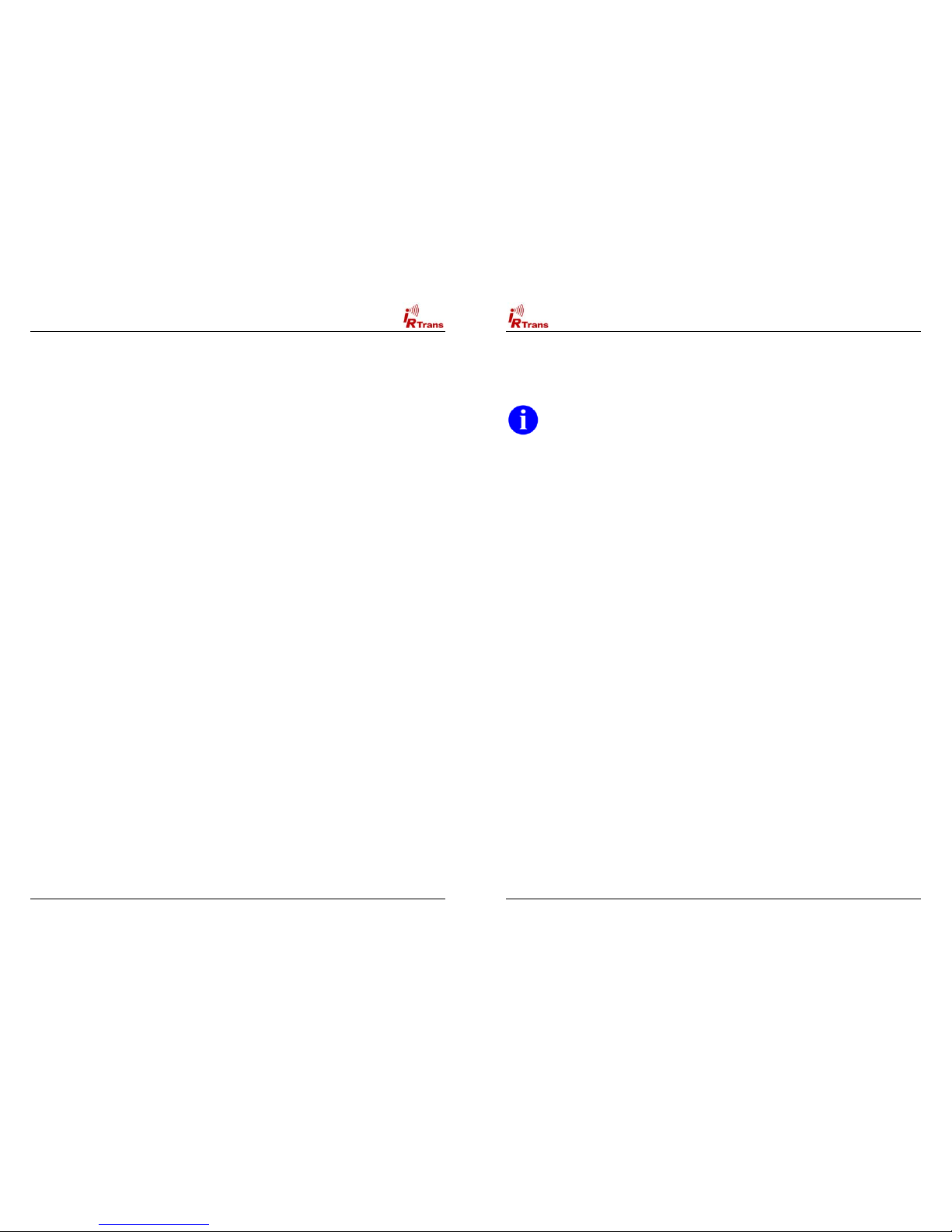
Users Manual IRTrans Version 2.12
15
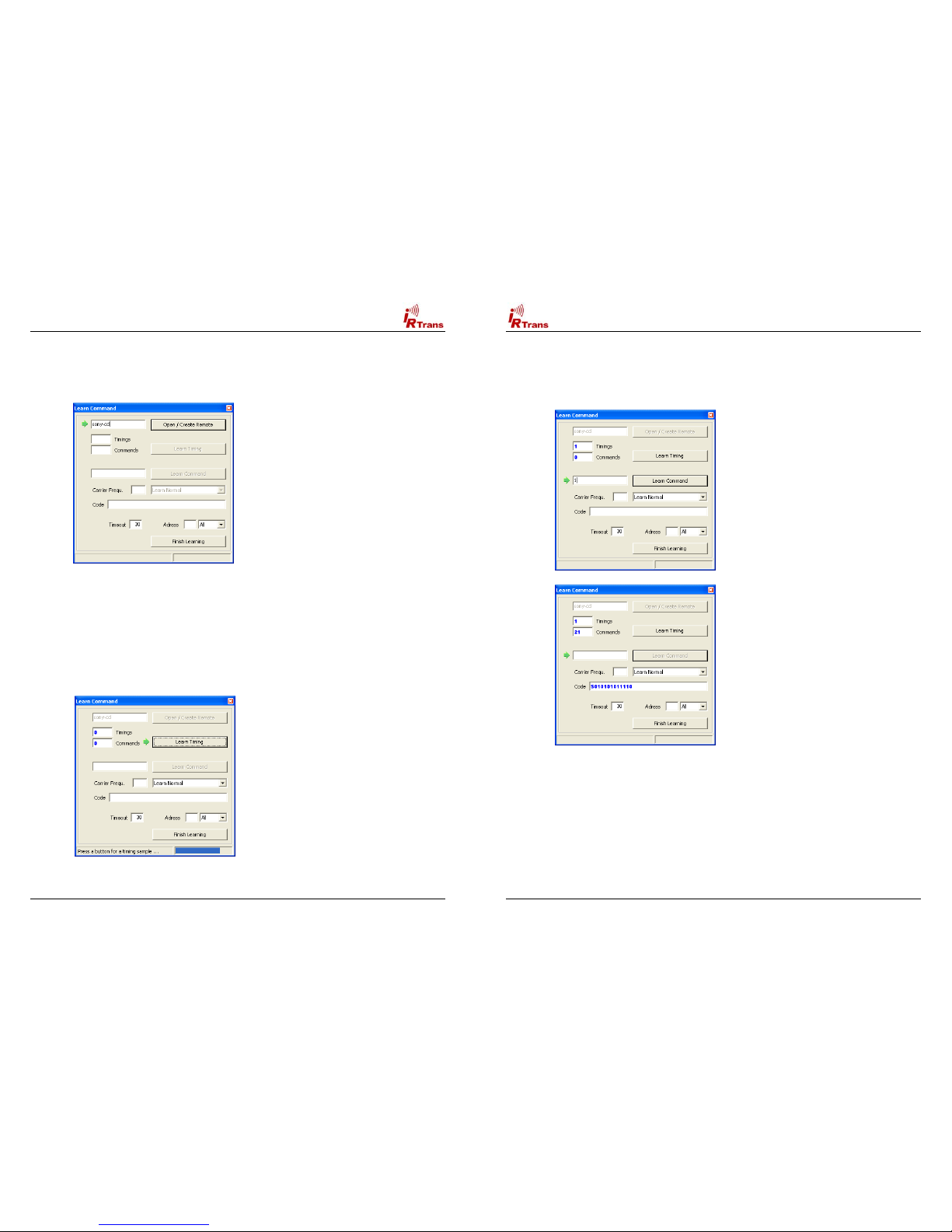
4.4. Format of the IRTrans IR Database
The IR Database stores the Infrared Codes, that can be sent and received by the
IRTrans in ASCII files. They have names ending in .rem. They are maintained by
the irserver. Because they are in ASCII format, these files can also be modified
or copied. When doing that it is important to use the correct syntax as errors in
the remotedefinitions may affect the stability of the software.
When the files are copied, it is important to also change the names of the
remote control at the beginning of the file.
After making manual changes to the remote database the server has to be
restarted manually.
In general there might be three different formats inside a .rem file:
!IRTrans Standard format (decoded commands):
[REMOTE]
[NAME]Sony
[TIMING]
[0][N]3[1]2408 608[2]600 600[3]1200 600[RC]2[RP]24[FREQ]40[SB][RS]
[COMMANDS]
[Stop][T]0[D]S000111010001
[Play][T]0[D]S010011010001
[Pause][T]0[D]S100111010001
[Next][T]0[D]S100011010001
[Prev][T]0[D]S000011010001
This is the standard format for IRTrans commands. The timing data is stored
apart from the IR commands itself.
Inside the files as many timings as desired can be stored. The discrete fields
have the following meaning:
[0][N]3[1]2408 608[2]600 600[3]1200 600[RC]2[RP]24[FREQ]40[SB][RS]
[0] : Number of the timing
[N][3] : Number of time values inside of this timing
[1]2408 608 : Pulse / Pause pair. Values in µs. The resolution is 8 µs.
[RC]2 : Number of repeats
[RP]24 : Pause between two repeats in ms.
[FREQ]40 : Carrier frequency of the IR signal (0 = Not modulated)
[SB] : Code uses a Startbit
[RS] : Startbit is repeated
[RC5] : RC5 Code (No timing info needed)
[RC6] : RC6 Code (No timing info needed)
The structure of the commands itself is as follows:
[Stop][T]0[D]S000111010001
[Stop] : Name of the command
[T]0 : This command uses timing 0
[D]S00011.. : Command data. Refers the Pulse / Pause Pairs in the timing.
Users Manual IRTrans Version 2.12
16
!IRTrans RAW Format (for unusual command formats):
[REMOTE]
[NAME]raw
[TIMING]
[COMMANDS]
[1][RAW]87[FREQ]38[D]0 8 368 592 600 592 608 592 600 592 600 592 …
[2][RAW]87[FREQ]38[D]0 8 344 616 1176 616 584 616 576 616 576 616 …
[3][RAW]87[FREQ]38[D]0 8 344 616 584 616 1176 616 576 616 576 616 …
[4][RAW]87[FREQ]38[D]0 8 376 592 1200 592 1200 584 608 592 600 592 …
[5][RAW]87[FREQ]38[D]0 8 344 616 576 616 584 616 1168 616 584 616 …
The RAW Format is used to learn commands, that can not be learned using the
standard format. In general they should not be used to control the PC. Controlling
the PC is only possible if the option “Use always RAW Codes” is activated in the
setting of the IRTrans module. Of course this codes can be sent the same way as
other commands. They are described by Pulse/Pause pairs in µs. Values of more
then 2.040 µs are coded in form of two bytes with a leading 0 byte. In general it
does not make sense to enter RAW Codes manually, it is simply to complicated.
!IRTrans CCF Format (for Commands used by the Philips Pronto™):
[REMOTE]
[NAME]ccf
[COMMANDS]
[1][CCF]0000 0067 0000 000d 0060 0018 0018 0018 0018 0018 0018 0018 0018 0018
0018 0018 0018 0018 0018 0018 0030 0018 0018 0018 0018 0018 0018 0018 0030 043c
[v+][CCF]0000 006d 0022 0002 0155 00aa 0016 003f 0016 0015 0016 003f 0016
003f 0016 003f 0016 003f 0016 003f 0016 0015 0016 0015 0016 003f 0016 0015 0016
0015 0016 0015 0016 0015 0016 0015 0016 003f 0016 003f 0016 0015 0016 003f 0016
003f 0016 0014 0016 0014 0016 0014 0016 003f 0016 0015 0016 003f 0016 0015 0016
0015 0016 003f 0016 003f 0016 003f 0016 0015 0016 05e7 0155 0055 0016 0e3b
The CCF Format allows to use the huge number of IR Codes available for the
Philips Pronto™for the IRTrans system. Currently all Mode 0, 1, 5 and 6 (first
Field = 0000, 0001, 0005, 0006) Commands can be used. These are almost all
files available for example at www.remotecentral.com. The codes that are used
have to be extracted using the Pronto Edit™Software. Informations about the
Philips Pronto™can be found at www.pronto.philips.com. New command files can
easily be created based on the file ccf.rem.
When copying definitions care should be taken to change the name of the
remote in the [REMOTE] section of the file..
In any case the terms of license provided Philips Corporation for the Pronto
Edit Software should be observed!