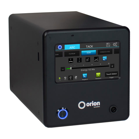
Orion 100C User manual

Orion Pulse Arc Welders User Manual
Orion 100c

100c User Manual
2
Table of Contents
Forward ........................................... p.3
Manufacturer’s Contact Information ............. p.3
Welding safety Precautions ...................... p.3
Chapter 1: setup and Assembly .................. p.7
What is in the Box ............................ p.7
Power Supply Setup .......................... p.8
Darkening Lens Setup* ....................... p.9
Base Microscope Setup* ..................... p.10
Microscope Arm Setup* ...................... p.11
Microscope Shutter System Setup ........... p.13
Become Familiar with the Microscope ....... p.13
Electrode Setup ............................... p.14
Shielding Gas Setup .......................... p.16
Chapter 2: Welder Overview ..................... p.18
Chapter 3: Pulse Arc Welding .................... p.24
Chapter 4: Tack/Resistance Welding ............ p.28
Chapter 5: Tungsten Electrodes ................. p.32
Chapter 6: Orion Techniques, Tips and Tricks ... p.37
Chapter 7: Metals ................................ p.43
Chapter 8: Maintenance ......................... p.51
Chapter 9: Updating Welder Software ........... p.53
Chapter 10: Technical Specification .............. p.53
Chapter 11: Troubleshooting/FAQ ............... p.54
Warranty Information ............................. p.59

3
OrionWelders.com
FOREWORD:
ank You for Choosing Orion Welders and congratulations on your purchase!
You are now the proud owner of an Orion 100c Welder. is manual was designed to help you set
up the welder and begin welding. Please read and follow all safety precautions before proceeding
with the welding process.
Sunstone Engineering is the parent company of Orion Welders. At Sunstone & Orion we are
committed to producing quality products and ensuring complete owner satisfaction. If you require
assistance after reading this manual please contact us with the information provided below.
Orion Welders, a Subsidiary of
Sunstone Engineering R&D Corp.
1693 American Way Suite #5
Payson, UT 84651
Email: sales@orionwelders.com
Voice: 801-658-0015
Fax: 866-701-1209
Welding Safety Precautions
READ BEFORE WELDING
e following safety advice is generalized advice for the arc-welding industry. ese safety
precautions are not all inclusive. All users should exercise reasonable caution while using this
device. e following group of symbols are warning symbols:
CAUTION, ELECTRIC SHOCK HAZARD, EYE PROTECTION REQUIRED.
Consult these symbols and the related instructions listed next to the symbols for proper action
when dealing with these hazards.
READ INSTRUCTIONS
• Read the owner’s manual before using the Orion.
• Only personnel trained and certified by the manufacturer should service the unit.
• Use only genuine replacement parts from the manufacturer.
SAFETY PRECAUTIONS FOR FIRE OR EXPLOSION
Sparks can fly off from the welding arc. e flying sparks, hot work piece, and hot

100c User Manual
4
equipment can cause fires and burns. Ensure that your work area is clean and safe for
welding before starting any weld job.
• Do not install or operate unit near combustible surfaces.
• Do not install or operate unit near flammables.
• Do not overload your building’s electrical wiring – be sure the power distribution
system is properly sized, rated, and protected to handle this unit.
• Remove all flammable materials from the welding area. If this is not possible, tightly
cover them with approved covers.
• Do not weld where flying sparks can strike flammable material.
• Protect yourself and others from flying sparks and hot metal.
• Watch for fire and keep a fire extinguisher nearby.
• Do not weld where the atmosphere may contain flammable dust, gas, or liquid
vapors.
• Remove any combustibles, such as butane lighters or matches, from your person
before doing any welding.
• Do not exceed the equipment’s rated capacity.
• Use only correct fuses or circuit breakers. Do not oversize or bypass them.
SAFETY PRECAUTIONS FOR ELECTRICAL SHOCK
Touching live electrical parts can cause fatal shocks or severe burns. e input power circuit and
the internal circuits of the Orion welder are live when the power switch is turned on. Additionally
the internal capacitors remain charged for a period of time after the Orion is turned off and/or
power is disconnected. Incorrectly installed or improperly grounded equipment is a hazard. is
device was designed to operate indoors only. Do not operate welder in a wet/damp environment.
Holding the hand pieces connected to the front of the welder is okay and will not generate an
electrical shock.
• Remove personal jewelry before welding (i.e. rings, watches, bracelets, etc).
• Do not touch live electrical parts.
• Wear dry, hole-free insulating gloves and body protection.
• Properly install and ground this equipment according to this manual and national,
state, and local codes.
• Do not weld with wet hands or wet clothing.
• Always verify the supply ground – check and be sure that the input power cord
ground wire is properly connected to a ground terminal in the disconnect box or that
the input power cord plug is connected to a properly grounded receptacle outlet. Do
not remove or bypass the ground prong.
• Keep cords dry, free of oil and grease, and protected from hot metal and sparks.
• Frequently inspect the input power cord and ground conductor for damage or
bare wiring – replace immediately if damaged – bare wiring can kill. Check ground
conductor for continuity.
• Turn off all equipment when not in use.
• Use only well-maintained equipment and repair or replace damaged parts at once.
PERSONAL PROTECTIVE EQUIPMENT RECOMMENDATIONS FOR FLYING SPARKS AND ARC RAYS
It is essential for every person in the immediate work area to wear/utilize proper
Personal Protection Equipment. Arc welding gives off infrared and UV rays that can
burn the retinal tissues within the eyes and cause surface burns to exposed skin,

5
OrionWelders.com
similar to a sun burn. Very often sparks fly off from the weld joint area; therefore, take
the necessary precautions to avoid trapping a spark within your own clothing.
• e stereo microscope provides proper eye protection when pulse-arc welding. No
additional protection is necessary.
• Wear protective garments such as oil-free, flame-resistant leather gloves, heavy
shirt, cuff-less trousers, high shoes, and a cap. Avoid synthetic fibers as they melt
easily.
• Use an approved face shield or safety goggles with side shields when tack welding or
when observing others performing pulse-arc and tack welds.
SAFETY PRECAUTIONS FOR HOT METAL
• Welding material that has a high thermal conductivity will cause metal to heat rapidly.
• Repetitive welds in the same location can cause metal to become hot.
• Do not touch hot weld areas bare-handed.
• Allow sufficient cooling time before handling welded pieces.
SAFETY PRECAUTIONS FOR FUMES AND GASES
Welding produces fumes and gases. Breathing these fumes and gases can be hazardous to your
health. e Orion produces minimal fumes and gases when compared to large-scale arc welders.
ough not required, some form of ventilation is recommended.
• Keep your head out of the fumes. Do not breathe the fumes.
• Ventilate the area and/or use local forced ventilation at the arc to remove welding
fumes and gases.
• If ventilation is poor, wear an approved air-supplied respirator.
• Read and understand the Material Safety Data Sheets (MSDS) and the manufacturer’s
instructions for metals, consumables, coatings, cleaners, and degreasers.
• Welding in confined spaces requires good ventilation or an air-supplied respirator.
Always have a trained watch person nearby. Welding fumes and gases can displace air
and lower the oxygen level causing injury or death. Be sure the breathing air is safe.
• Do not weld in locations near degreasing, cleaning, or spraying operations. e heat
and rays of the arc can react with vapors to form highly toxic and irritating gases.
• Do not weld on coated metals, such as galvanized, lead, or cadmium plated steel,
unless the coating is removed from the weld area, the area is well ventilated, and
while wearing an air-supplied respirator. e coatings and any metals containing
these elements can give off toxic fumes if welded.
SAFETY PRECAUTIONS FOR FALLING EQUIPMENT
• Use a working surface of adequate physical strength to support the welding unit
during operation or storage.
• Secure welding unit during transport so that it cannot tip or fall.
SAFETY PRECAUTIONS FOR HIGH FREQUENCY PITCH AND VOLUME
• Welding with high frequency pulse agitation can produce loud, high pitched sounds. It
is recommended to use hearing protection when welding with agitation turned on.

100c User Manual
6
MAGNETIC FIELDS CAN AFFECT IMPLANTED MEDICAL DEVICES
• Wearers of pacemakers and other implanted medical devices should keep away.
• Implanted medical device wearers should consult their doctor and the device
manufacturer before going near arc welding, spot welding, gouging, plasma arc
cutting, or induction heating operations.
OVERUSE CAN CAUSE OVERHEATING
• Allow a cooling period between strenuous welding schedules; follow rated duty cycle.
• If overheating occurs often, reduce duty cycle before starting to weld again.
OBSERVE ALL NECESSARY PRECAUTIONS ASSOCIATED WITH COMPRESSED GASES
• Use only compressed gas cylinders containing the correct shielding gas for the
process used.
• Always keep cylinders in an upright position and secured to a fixed support.
• Cylinders should be located:
- Away from areas where they may be struck or subjected to physical damage.
- A safe distance from arc welding or cutting operations and any other source of
heat, sparks, or flame.
PRINCIPAL SAFETY STANDARDS
Safety in Welding, Cutting, and Allied Processes, ANSI Standard Z49.1,from Global Engineering
Documents (phone: 1-877-413-5184, website:www.global.ihs.com).
OSHA, Occupational Safety and Health Standards for General Industry, Title 29, Code of Federal
Regulations (CFR), Part 1910, Subpart Q, and Part 1926, Subpart J, from U.S. Government Printing
Office, Superintendent of Documents, P.O. Box 371954, Pittsburgh, PA 5250-7954 (phone:
1-866-512-1800) (there are 10 Regional Offices—phone for Region 5, Chicago, is 312-353-
2220, website: www.osha.gov).
National Electrical Code, NFPA Standard 70, from National Fire Protection Association, P.O. Box
9101, Quincy, MA 02269-9101 (phone: 617-770-3000, website: www.nfpa.org and www.sparky.
org).
Canadian Electrical Code Part 1, CSA Standard C22.1, from Canadian Standards Association,
Standards Sales, 5060 Mississauga, Ontario,
Canada L4W 5NS (phone: 800-463-6727 or in Toronto 416-747-4044, website: www.csa-
international.org).
Safe Practice For Occupational And Educational Eye And Face Protection, ANSI Standard Z87.1,
from American National Standards Institute, 25 West 43rd Street, New York, NY 10036–8002
(phone: 212-642-4900, website: www.ansi.org).
CE TESTED AND CERTIFIED
Welder tested for electrostatic discharge immunity up to 2kV for CE compliance

7
OrionWelders.com
ch.1
CHAPTER 1: WELDER SETUP & ASSEMBLY
What is in the Box
A video explanation of these items below can be found at http://www.orionwelders.com/
resources/orion-c-series-resources/
e Orion 100c will arrive in 2 boxes.
BOX 1:
(1) User Manual & Quick Start/Quick Settings Guide
(1) Orion 100c Power Supply
(1) Welder Power Cord
(1) Stylus Hand Piece
(2) Alligator Clips
(1) Foot Pedal
(1) Shielding Gas Hose
(1) Cross Lock Tweezers
(1) Electrode Vile (5 – 0.5mm and 5 – 1.0mm Electrodes)
(1) Fiberglass Brush
BOX 2 IF YOU PURCHASED THE BASE MICROSCOPE SYSTEM:
(1) Base Microscope
(1) Base Microscope Power Cord
(2) Microscope Eye Piece Shields
(1) Green System Cover
BOX 2 IF YOU PURCHASED THE MICROSCOPE ARM SYSTEM:
(1) Orion 100c Microscope Arm
(1) Microscope Arm Table Mount
(1) Microscope Arm Support Bar
(1) Set of Allen Wrenches
(2) Microscope Eye Piece Shields
(1) Green Cover
(1) Brass Lined Pliers
BOX 2 IF YOU PURCHASED THE DARKENING LENS SYSTEM:
(1) Base Plate and Phillips Screw
(1) Base Plate Stand and Cap
(1) Darkening Lens
(1) Darkening Lens Arm
(1) RJ45 Darkening Lens to WelderCable
(1) Setup Sheet

100c User Manual
8
ch.1
Power Supply Setup (backside)
SET UP THE BACK SIDE OF THE POWER SUPPLY
e Orion has an internal switching power supply that can accept both 120 and 240VAC. A video
explanation of the steps below can be found at http://www.orionwelders.com/resources/orion-
c-series-resources/
1. Plug the female end of the power cable into
the “AC Power” port on the back of the power
supply. en connect the male end into AC
power.
2. Insert the 1/4” gas tube firmly into the “Gas”
port on the back of the welder. *It may wiggle
when connected, but should not come out if
pulled on.
3. Plug the foot pedal into the “foot pedal” port
on the back of the power supply.
4. Plug the RJ45 Microscope cable into the RJ45
port.
Power Supply Setup (frontside)
CONNECT THE WELDING STYLUS TO THE FRONT OF THE POWER SUPPLY
A video explanation of connecting the welding stylus to the power supply can be found at http://
www.orionwelders.com/resources/orion-c-series-resources/
e welding stylus requires the most attention during setup. Since argon gas will flow through the
stylus, a tight fit between the power supply and the stylus is critical. is will insure that no oxygen
is entrained into the weld. To accomplish this, follow the steps below.
1. Position the end of the stylus so that the notch is facing up.
2. Push the stylus into the stylus connector port on the front panel of the power supply.
3. Turn the outside layer of the stylus connector clockwise so it screws onto the stylus
connector port.
4. Continue to turn the outside layer of the stylus connector clockwise until it stops.
5. Now push in on the stylus connector, and then turn the outside layer of the stylus connector
again until it will no longer turn.
6. Repeat steps 2-5 until you feel the stylus connector bottom out, and you can no longer screw
the stylus connector clockwise. is will insure that the stylus connector is firmly seated.

9
OrionWelders.com
ch.1
7. Place an alligator clip into the positive port on the front
panel of the welder. *Remember to attach the alligator
clip to the work piece before welding.
Darkening Lens Setup
SET UP THE DARKENING LENS
e Orion’s darkening lens system is easy to use. e darkening lens will automatically darken
when the weld takes place. is allows the user to have a magnified view of the work piece
and protection from the flash during the welding process. A video explanation for setting up
the microscope can be found at http://www.orionwelders.com/resources/orion-c-series-
resources/
1. Remove Darkening Lens parts from the box and place
them on your workbench.
2. Connect the Base Plate to the Base Plate Stand by
running the included Phillips screw through the bottom
of the Base Plate into the Base Plate Stand. (e Phillips
screw will be attached to the bottom of the Base Plate
Stand. Unscrew it then follow this step)
3. Slide the Darkening Lens Arm onto the Base Plate
Stand. Adjust it to your desired height then tighten the
Darkening Lens Arm knob.
4. Place the Base Plate Stand Cap on top of the Base Plate
Stand.
5. Adjust the Darkening Lens Position by loosening/tightening
the adjuster knobs on the front of the Darkening Lens Arm.
6. Plug the RJ45 Darkening Lens cable into the Darkening Lens
light ring and the other end of the cable into the “Foot Pedal/
Microscope” port on the back of the welder.
7. Insert the Orion stylus into the Stylus Holder on the
Darkening Lens Arm. Adjust the position of the stylus by
loosening/tightening the adjuster knobs on either side
of the Darkening Lens Arm.
Base Plate
Stand Cap
Base Plate
Stand
Base Plate
Phillips Screw
Darkening
Lens Arm
Darkening
Lens Arm
Knob
Darkening
Lens
5.
6.

100c User Manual
10
Base Microscope Setup
SET UP THE BASE MICROSCOPE
A video explanation for setting up the microscope can be found at http://www.orionwelders.
com/resources/orion-c-series-resources/
1. Raise the microscope head to the desired
height, and then tighten it into place on
the base rod.
2. Raise the microscope head height lock
directly underneath the microscope head,
then tighten it to the base rod.
3. Raise the stylus rod holder to the desired
height, and then tighten it into place on
the base rod.
4. Insert the stylus rod into the stylus rod
holder then tighten the rod into place.
5. Insert the welding stylus into the stylus
holder on the stylus rod. Slide the stylus
into the holder until it stops then tighten
the holder.
6. Ensure the microscope cable is plugged into the microscope shutter light ring.
7. Plug the other end of the microscope cable into the “Microscope” port on the back of the
power supply.
CONFIGURE THE BASE MICROSCOPE
e microscope can be configured in many different ways to suit your individual preference. Orion
highly recommends configuration # 3 as the simplest to use and implement. In this configuration
the user has an unobstructed space for hand and work piece placement. is configuration also
allows the welding stylus to easily be adjusted to different angles.
1. Microscope facing forward, work piece brought to stylus from front.
2. Microscope head rotated 90deg from body, work piece drawn toward user to touch the stylus.
3. Microscope head rotated 90deg from body, work piece lifted away from the user to touch the
stylus. (is drawing is the same set up as the above image listing the microscope parts )
Microscope Head
Adjustment
Microscope Focus
Microscope Head
Height Lock
Stylus Rod
Holder
Stylus Rod
Welding Stylus
Stylus Holder
Microscope
Power Switch
Microscope Light
Ring Brightness
Base Rod
Light Ring Plug
Eye Piece
Shields
Microscope Head
Swivel Lock
1. 2. 3.
ch.1

11
OrionWelders.com
ch.1
FOCUS THE BASE MICROSCOPE
1. Move the microscope head up or down to a comfortable height.
2. Adjust the stylus rod so the stylus is at a 45-degree angle.
3. Adjust the stylus rod holder up and down to a height that gives the user room to position their
hands underneath the stylus and lift the work piece upward to the stylus.
4. Twist the Microscope Focus knob to focus the microscope.
When adjusting the microscope focus, place your finger at the tip of the
welding stylus to help judge the correct focus location. Focus the microscope
till the texture on the skin of your finger is clearly visible.
Microscope Arm Setup
MICROSCOPE ARM MOUNTING OPTIONS
A video explanation of the 3 different mounting options can be found at
http://www.orionwelders.com/resources/orion-c-series-resources/
Mounting Option 1 - Clamp to table
1. Determine the height of the tabletop. *If it is thicker than 2-3/4’
(7cm), follow arm base mounting options 2 or 3.
2. Position the microscope arm clamp under the tabletop.
3. Turn the clamp knob clockwise until the clamp is very snug.
Mounting Option 2 - Bolt through table
1. Using the provided allen wrench, unscrew
the 10m x 1.5 allen bolt underneath the
arm base.
2. Drill a 3/8’ (10mm) hole through the
tabletop.
3. Place a washer on the 10m x 1.5 bolt
(length will depend on tabletop thickness)
and run it up through the tabletop into the arm base.
4. Tighten the bolt until it is very snug.
Mounting Option 3 - Bolt to table
1. Position the base against the table.
2. Trace drill holes with a pen or marker.
3. Drill 1/4’ holes in the tabletop.
4. Run screws through the base into the drilled
holes.
2¾”

100c User Manual
12
ch.1
MICROSCOPE ARM SETUP
A video explanation of the microscope setup can be found at http://www.orionwelders.com/
resources/orion-c-series-resources/
1. Place the upper half of the microscope arm into the arm base.
2. Install the rubber eyepiece covers.
3. Insert the welding stylus into the stylus holder
under the microscope head then tighten the stylus
holder knob.
4. Loosen the bolt in front of the microscope mount
to move the microscope head left and right.
5. Loosen/tighten the allen on the microscope
arm to adjust the spring pressure. Turn the allen
clockwise if the arm does not hold the microscope
up. Turn the allen counter clockwise if the arm does
not allow the microscope to come down.
6. Ensure the microscope cable is plugged into the microscope shutter
light ring (this is an RJ45 port at the bottom of the microscope head).
7. Plug the other end of the microscope cable into the “Microscope” port
on the back of the power supply.
ADJUST WELDING STYLUS POSITION
A video explanation of the steps below can be found at http://www.orionwelders.com/
resources/orion-c-series-resources/
1. Loosen the screws on either side of the stylus holder.
2. Adjust the welding stylus to a 45-degree angle then slightly
tighten the screws just enough to hold the stylus in place at a
45-degree angle
3. While looking through the microscope, slide the welding
stylus holder forward/backward until the tip of the stylus is
in the center of your focus.
4. Now securely tighten the stylus holder screws.
5.
4.
3.
2.
1.
2. 45°

13
OrionWelders.com
ch.1
ADJUST THE MICROSCOPE FOCUS
A video explanation of the microscope configuration options can be found at http://www.
orionwelders.com/resources/orion-c-series-resources/
1. Twist this knob left and right in order to focus the microscope.
When adjusting the microscope focus, place a finger under the
welding electrode to help judge the correct focus location. Focus the
microscope till the texture on the skin of the finger is clearly visible.
Microscope Shutter System Setup
e shutter allows an unobstructed working view before welding and completely protects the
user’s eyes during the welding process. e Orion’s internal computer verifies the shutter has
been closed before allowing the weld to take place. e Orion will not allow a weld to take place if
the shutter does not completely shut.
Shutter Troubleshooting:
1. Turn off the unit and then turn it back on. is will
reset the shutter.
2. If step 1 does not correct the issue, the shutter
switches can be moved manually. To do this,
remove the lens cap under the shutter and
manually move the shutter switches. (is
should be an easy movement. If it is not call in for
additional troubleshooting).
Become Familiar with the Microscope
A video explanation of becoming familiar with the microscope can be found at http://www.
orionwelders.com/resources/orion-c-series-resources/
e Orion Microscope has been designed to provide maximum visual clarity, eye protection and
ease of use. One challenge using the microscope is getting used to bringing the work piece to the
welding electrode while looking through the microscope. is is an easy challenge to overcome.
To begin, follow these steps with the welder on pause. *While the welder is on pause it will not

100c User Manual
14
ch.1
weld when the work piece touches the electrode.
1. Rest your hands on the table and position the
work piece close to the welding electrode before
looking into the microscope.
2. Make sure your focus is at the tip of the electrode.
3. Use slow, controlled movements.
4. It is helpful to have your hands resting and to only
use your fingers to move the work piece up to the
electrode.
5. Place the work piece surface perpendicular to the
point of the electrode. *As will be discussed, the angle of the electrode tip relative to the work
piece surface is very important and will take practice.
6. Now practice making light contact with the work piece to the electrode.
*Remember to follow these steps once the welder is completely set up ready to begin welding.
Electrode Setup
e Orion welder comes standard with a 0.5mm electrode collet and (5)
0.5mm electrodes; and a 1.0mm electrode collet and (5) 1.0mm electrodes.
e 1.0mm electrodes are a good all around electrode while the 0.5mm
electrode is excellent for very small projects (less than 5ws of energy).
Stylus components:
1. Stylus Shaft 2. Collet 3. Collet Cap 4. Electrode 5. Stylus Hull
INSTALL THE TUNGSTEN ELECTRODE ONTO THE WELDING STYLUS
Follow these steps to properly install the tungsten electrode. A video explanation of the steps
below can be found at http://www.orionwelders.com/resources/orion-c-series-resources/
1. Remove the stylus hull by pulling it away from the stylus.
2. Loosen the collet cap by twisting it counter-clockwise.
3. e welder comes with 2 electrode collets. One that fits 0.5mm electrodes and one that
fits 1.0mm electrodes. e electrode stylus will be shipped with the 1.0mm electrode collet
installed.
4. Insert the 1.0mm electrode into the collet. Helpful Tip: Make
a mark around the Stylus Hull that will help measure the
electrode length. Place the end of the stylus hull up against
the collet cap then make sure the electrode tip falls between
mark.
5. ere should be between 0.6 - 0.7in (1.5 – 2cm) of the
electrode protruding from the stylus shaft. is will allow the electrode enough room to stick
out from the stylus once the stylus hull is placed back on the stylus.)

15
OrionWelders.com
ch.1
6. Lock the electrode into place by hand tightening the collet cap
in a clockwise direction.
7. Replace the stylus hull by pushing it snuggly until you feel it
snap back into place (the electrode should stick out between 1/8 –
1/4in (3.75 – 6.75mm) after the stylus hull is snapped back into place).
WORK PIECE TO ELECTRODE PRESSURE
A video explanation of the instruction below can be found at http://www.orionwelders.com/
resources/orion-c-series-resources/
Touch the work piece to the electrode with very light pressure. Too much pressure will cause
the work piece to stick to the electrode and in turn cause the electrode to be contaminated
(work piece material on the electrode). is will shorten the amount of time you can weld before
re-sharpening or replacing the electrode. *As a general rule of thumb we recommend a freshly
sharpened electrode anytime a new work piece is being welded.
WHEN TO SHARPEN THE ELECTRODE
It is recommended that the user pay close attention to the electrode condition. An electrode that
appears to be dark colored or covered with material from previous welds can lead to inconsistent
welding and poor igniting of the weld. When this occurs, simply sharpen the electrode with the
included diamond disk. e diamond disk can be attached to a flex shaft or Dremel tool. Follow
these steps for sharpening the electrode. A video explanation of the steps below can be found at
http://www.orionwelders.com/resources/orion-c-series-resources/
1. Completely remove the electrode from the stylus.
2. Pinch the electrode between the thumb and middle finger with the point facing inward.
3. Power on the Dremel or flex shaft then hold it with
the opposite hand. *If the Dremel is in the left
hand, then sharpen the electrode on the side of the
diamond disk furthest from the body. If the Dremel
is in the right hand, then sharpen the electrode on
the side of the diamond disk closest to the body.
e reason for this is to keep the striations on the
electrode moving towards the electrode tip, not
away. is will effect the quality of the weld if not
done as explained above.
4. Set the electrode on the diamond disk at a 10-degree angle and begin to spin the electrode
with the thumb and middle finger. *A helpful way to get a sharp electrode is to push down on
the electrode with your index finger while twisting the electrode with the thumb and middle
finger. See the video on our website for additional instruction on this method.
5. Once the electrode is sharp and clean, turn the Dremel off and insert the electrode back into
the stylus as explained above.
*See Chapter 5 for additional information on the Tungsten Electrodes

100c User Manual
16
ch.1
WHEN TO FLATTEN/BLUNT THE ELECTRODE
When working with silver, copper, and other highly conductive metals in energy levels above
20ws, it is recommended to blunt the electrode instead of sharpening it. A video explanation
of the steps below can be found at http://www.orionwelders.com/resources/orion-c-series-
resources/
1. Completely remove the electrode from the stylus.
2. Pinch the electrode between the thumb and middle finger with the point facing inward.
3. Turn the Dremel or flex shaft on then hold it with the opposite hand. *If the Dremel is in the
left hand, then sharpen the electrode on the side of the diamond disk furthest
from the body. If the Dremel is in the right hand, then sharpen the electrode on
the side of the diamond disk closest to the body. e reason for this is to keep the
striations on the electrode moving towards the electrode point, not away. is will
effect the quality of the weld if not done as explained above.
4. Set the electrode on the diamond disk at a 10-degree angle and begin to spin
the electrode with the thumb and middle finger. *A helpful way to get a sharp
electrode is to push down on the electrode with your index finger while twisting the
electrode with the thumb and middle finger.
5. Once the electrode is sharp and clean, turn the electrode to a 90-degree angle and
push it against the dremel in order to place a flat/blunt tip on the electrode.
6. Once the electrode has a flat/blunt tip, turn the Dremel off and insert the
electrode back into the stylus as explained above.
See the Orion Workbook for additional details about the Tungsten Electrodes.
Shielding Gas Setup
During the pulse-arc welding process high temperature plasma quickly melts metal into a
molten pool. As the weld is performed, a small amount of shielding gas is released through the
weld stylus to prevent oxygen from entering the molten pool. After the weld has occurred the
protective gas turns off.
If oxygen from the air enters this molten pool, the result is a metal oxide that is brittle, porous
and burnt-looking. Protective shielding gas is used, such as 99.996% pure Argon (Argon 4.6)
or higher, to prevent these effects. Shielding gas is necessary to produce clean and repeatable
pulse-arc welds. We recommend high purity argon. is can be purchased at your local welding
supply shop.
PRESSURIZED GAS SAFETY
ere are several important rules that should be followed when using a compressed shielding gas
such as argon.
1. Always secure the pressurized gas tank to a fixed location (such as a sturdy table leg). If the
pressurized gas cylinder were to tip and become damaged there is possibility that the tank
could become rocket-like, expelling the high pressure shielding gas as propellant.
2. ALWAYS TURN OFF THE SHIELDING GAS AT THE MAIN VALVE WHEN FINISHED. is will help
your shielding gas supply last longer in case there is a small leak in the tubing. is is also

17
OrionWelders.com
ch.1
a good safety practice. If the tube becomes dislodged, shielding gas could fill the room
displacing needed breathing oxygen. Argon is heavier than air and will fill the room from
the bottom upward. If you experience a large shielding gas leak, open all of the doors and
windows in the room.
SHIELDING GAS TANK AND REGULATOR SETUP
A video explanation of the steps below can be found at http://www.orionwelders.com/
resources/orion-c-series-resources/
1. Ensure that your shielding gas tank is securely fastened to a stationary point near the welding
area.
2. Turn the regulator dial COUNTER CLOCKWISE (closed) until it is fully backed out to prevent
over-pressurization of the line.
3. Screw the gas regulator onto the shielding gas tank.
4. Connect one end of the gas tubing to the gas regulator.
5. Insert the other end of the gas tubing into the gas port on
the back of the power supply. It will stop when it is fully
connected. Tug gently on the tube to verify a tight fit.
6. Open the gas tank slowly. e dial on the right should pressurize and the dial on the right
should remain at zero (when the regulator dial is fully backed out – see step 2).
7. Slowly turn the regulator dial CLOCKWISE until the gas pressure reads between 7-10 psi. (is
will adjust the dial on the left side of the regulator.)
Regulator Dial

100c User Manual
18
CHAPTER 2: THE TOUCH SCREEN INTERFACE
e Orion touch screen interface is very user friendly. Users have access to every welding
parameter with one touch. Below is an explanation of all the various buttons and options found
on the Orion interface. *Orion touch screens are resistive touch screens. is means they respond
best to a little bit of pressure. e end of your fingernail or the tip of the alligator clip works best
when touching the screen.
e Main Screen
e arc screen is the main screen that users will be on for pulse arc welding. From this screen
users can make every adjustment necessary for the welding process. Below is a description to
everything you see on the arc screen. We will start at the bottom right and work our way up.
PLAY/PAUSE BUTTONS
Play - In order to weld, the play/pause button must show the green triangle “play“ symbol.
Pause - If the welder is not going to be in used for a period of time, users can push the play/
pause button (a grey pause symbol will appear). is will keep the unit powered on, but welding
functions will be disabled.
RESET BUTTON
e reset button will place all settings on the welder back to their factory default settings. e
factory default settings are “safe” settings and will work well with any metal. If the user is not sure
what settings to use, the factory default settings are a good starting point
BACK BUTTON
e back button will step backwards, allowing users to ‘undo’ up to 10 touch settings made on the
touch screen.
TRIGGER BUTTON
Auto Trigger - When using the Auto Trigger mode (recommended), the unit will automatically
initiate the weld once the work piece touches the electrode tip.
ch.2

19
OrionWelders.com
ch.2
Foot Pedal - When using the Foot Pedal mode, the weld will only initiate when the foot pedal is
pressed (the work piece must be touching the electrode or nothing will happen when the user
presses the foot pedal). is mode is recommended if users need to reach a deep crevice or a
tight area where they do not want the weld to automatically initiate if they accidentally touch a
sidewall with the electrode. *Remember to touch with lite pressure no matter what trigger mode
is being used.
AGITATION BUTTON
High Frequency Pulse Agitation can improve weld formation and strength. Agitation can be an
extremely valuable option with certain metals. See quick settings guide for when to use agitation.
Agitation Off - is is the standard weld discharge curve with a smooth slope.
is is good for most metals and will give maximum control over spot size
formation. is is the recommended setting when working with silver.
Agitation On - Agitation offers additional energy during the weld for additional
penetration and enhanced weld strength. e agitation energy can affect
the spot size. It is recommended to lower the overall weld energy slightly to
compensate for the additional agitation energy.
*Note: Agitation can produce loud, high-pitched sounds; please take precaution if ears are
sensitive
ENERGY BAR
e energy bar ranges from 3.0Ws (Watt-Seconds or Joules) to 100Ws. Users can slide their finger
anywhere along the bar to move the energy up or down.
PLUS/MINUS BUTTONS
Another option for moving the energy up or down is to use the + and - buttons to the right of the
energy bar.
SPOT WIDTH & SPOT DEPTH
is section of the touch screen interface shows the user an image of the estimated weld spot
width and weld spot depth (based on where the energy is set). is is roughly the size and
penetration that will occur when a weld is made. e dimension is also shown in millimeters.

100c User Manual
20
Load Button
e Load Button opens five “Factory Presets” and five “User Created” weld settings (User Created
slots will read as “empty slot” until a User Created setting is saved. See save button to learn how
to do this). is feature allows users to tell the Orion what type of metal they are welding or which
saved setting they would like to load. After selecting a factory preset or user created option, the
Orion will calibrate itself to the settings of that preset.
1. Touching the “Load” button
at the top left of the user
interface.
2. A list of “Factory Preset”
metals will appear on the
left, and previously saved
“User Created” options will
appear on the right.
3. Select the type of metal
being welded or previously
saved User Created option.
4. Touch the “Load” button at
the top right of the screen
and the system is calibrated
to that setting.
Save Button
is feature will save the users current Weld Energy, Agitation, Trigger Type, and all the current
settings in the settings tab (ie Pre-Flow Delay, Post-Flow Delay, Accelerator, Pre-Weld, Retract
Delay, and Weld Time/Duration). To begin, touch the “Save” button at the top left of the interface
then follow these steps:
1. Chose an empty slot in the
middle of the screen.
2. Touch the Save button at
the top right hand side of
the screen.
*When users go to load this
saved setting it will read
as the energy setting in
Watt Seconds. Be sure to
remember what the saved
energy setting was in order
to load this saved setting.
ch.2
Table of contents
Other Orion Welding System manuals
Popular Welding System manuals by other brands

Miller Electric
Miller Electric Big 40 WG owner's manual

Esta
Esta MOBEX F W3 operating instructions

Red-D-Arc
Red-D-Arc SuitCase 12VS owner's manual

Lincoln Electric
Lincoln Electric VANTAGE 500 (CE) IM894-B Operator's manual

Parkside
Parkside PIFDS 120 A1 Operation and safety notes

Draper
Draper 70049 manual