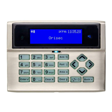
Orisec CP-25 User manual

CP-25 & CP-50
User Guide
Designed and Manufactured
in the United Kingdom
www.orisec.co.uk

2

3
Notes

4
Contents
1.About your Security System .............................................................................................. 6
Introduction ......................................................................................................................................... 6
About this Manual ............................................................................................................................. 6
Alarm Transmission System ............................................................................................................ 6
Zones and Areas ................................................................................................................................ 6
Access code ......................................................................................................................................... 6
NFC Tags .............................................................................................................................................. 7
Keypads ................................................................................................................................................ 7
Emergency Keys ............................................................................................................................... 10
2.Operating your Security System ..................................................................................... 12
Introduction ....................................................................................................................................... 12
User Menu ......................................................................................................................................... 12
Before Arming the Security System ............................................................................................ 12
Full Arming Your Security System ............................................................................................... 13
Part Arming your Security System ............................................................................................... 14
Disarming your security system ................................................................................................... 15
Area full arming ................................................................................................................................ 16
Area part arming .............................................................................................................................. 17
Area disarming ................................................................................................................................. 18
Resetting after an alarm ................................................................................................................. 19
Resetting after a Fault Condition ................................................................................................. 20
Omitting Zones ................................................................................................................................ 21
Changing Your Code ...................................................................................................................... 22
Turn chime on/off ............................................................................................................................ 23
System Event Logs ...........................................................................................................................24
View event log .................................................................................................................................. 25
View mandatory log ........................................................................................................................ 25

5
View chime log ................................................................................................................................. 26
Print Log ............................................................................................................................................. 26
System Tests ...................................................................................................................................... 32
Test Bell & Strobe ............................................................................................................................ 33
Walk Test Zones ...............................................................................................................................34
View Inactive Zones ........................................................................................................................ 35
View Zone Status ............................................................................................................................. 36
View Module Status......................................................................................................................... 37
Do a Test Call .................................................................................................................................... 38
Review Voice Messages ................................................................................................................. 38
Send SMS Message ......................................................................................................................... 39
3.Additional Features ........................................................................................................... 40
4.Troubleshooting ................................................................................................................. 41

6
1. About your Security System
Introduction
Your security system is made up of several component parts comprising of a control panel,
one or more remote keypads, external sounder and various detection devices that are
connected to either the control panel or zone expansion modules. The control panel houses
the system’s electronics and stand-by battery and is normally installed out of sight in a utility
room or under stairs cupboard etc.
The remote keypad provides the user interface for the system and is used to send commands
to the system and to display the current system status via a graphic display. The remote keypad
also provides audible feedback annunciation of fault and alarm tones. Remote keypads are
normally mounted in convenient locations inside the protected premises, near to the points of
entry and exit.
Please read this manual carefully and have your installer instruct you on your system’s
operation. Become familiar with the features that have been implemented on your system. All
users of this system should be equally instructed in its use.
About this Manual
This manual provides a thorough explanation of all system functions that are available to the
master user, including basic system operation, user code programming, remote control and
troubleshooting.
Alarm Transmission System
Your security system maybe fitted with an automatic alarm transmission system, which will
communicate alarms, faults and other events to a 24hr manned Alarm Receiving Centre (ARC).
If you accidently cause a false alarm activation, immediately call the ARC to prevent an
unnecessary emergency response.
Zones and Areas
A zone is an input that is normally used to monitor a single detection device like a motion
detector, glass-break detector, door contact or shock sensor etc. An area is one or more zones
grouped together to allow independent arming and disarming of areas.
Access code
As a user of the security system, you will be assigned a 4, 5 or 6 digit access code. Access codes
are used to arm and disarm the system. Some access codes can perform additional system
functions, such as programming system options, omitting zones and performing system tests.

7
Your access code may not allow you to access certain system functions. For instance, if your
code is only allowed to arm the system you will not be able to disarm the system, once the
system is armed.
NFC Tags
NFC (Near Field Communication) tags can be assigned to users of the system. The tag behaves
just like an access code when presented to the NFC reader built into the keypad. NFC
technology is built into credit cards, bank cards, smart phones and other devices.
Keypads
One or more remote keypads will be installed throughout the protected premises, usually close
to the entry and exit door.
Keyed Keypad Layout
1. LCD display
2. NFC reader – present your NFC tag in this area
3. Status Icons
4. System status LED
5. Ambient light sensor – used automatically adjusts the keyboard and LCD backlight level
6. Keyboard – see below

8
Keyed Keypad buttons Actions
AArm system
PPart arm system
aArea arm system
ESelection button
c Chime tone selection
B Escape button
C Cancel button
Touch Keypad Layout
1. Full colour touch display
2. NFC Reader – present your NFC tag in this area
3. Status Icons
4. System status LED

9
Touch Keypad buttons Function
Arm system
Part arm system
Area arm system
Selection button
Chime tone selection
Escape button
Cancel button
Status Icons
The system status area on the display is used to show the following information:
Status Icon Indicates
#$%K Battery is charging/ is charged
L Mains power is connected
& Mains power is disconnected
p External strobe is flashing
M External bell is sounding
N Chime is enabled
Q WiFi module connected
T GSM module connected
H Ethernet module connected
Z Phone line connected
3 User programmed timer running
[ User programmed alarm running
Status LED
The keypad has a single multi-colour LED and is used to Indicate the following:
Colour System Status
Blue Normal operation, all zones are healthy
Green User menu selected and system is ready for arming
Yellow One or more zones are active, system may not arm
Red Alarm active

10
Emergency Keys
The keypad provides 3 different emergency functions. Depending on the setup of your system,
activation from these keys can alert the local police, key holders and security personal via your
Alarm Receiving Centre (ARC).
The emergency keys for each keypad can be individual enabled or disabled and may
not be enabled on your installation due to local standards and police requirements.
The Panic alarm (Police) function for each keypad can be programmed for either an
audible or silent operation.
Keyed Keypad Emergency Keys
To activate the emergency functions, press together the keys shown below for a duration of 1
second:
Emergency Alarm Keys
Fire Press 1 & 3
Panic Alarm (PA) Press 4 & 6
Medical Press 7 & 9
Touch Keypad Emergency Keys
1. To activate the emergency keys on your touch screen keypad you will need to be on the
Home screen:
2. From the top part of the screen select one of the emergency functions, for example ‘Fire’:

11
3. You will then be prompted to press the Fire Alarm icon, and then select the icon again
to confirm the activation. This is in place to ensure it is a confirmed event and not an
accidental button press:
4. Press the ‘CONFIRM’ icon to generate the selected emergency or press the ‘Back’ icon
to cancel.

12
2. Operating your Security System
Introduction
Before attempting to operate your security system, please ensure that you have familiarised
yourself with the procedures covered in this section of the manual.
User Menu
On entering a valid access code or presentation of a tag the keypad will display the ‘User Menu’.
This menu is used to perform all system operations including arming, disarming, testing and
system configuration.
Before Arming the Security System
Before attempting to arm your security system, ensure that all protected areas are secure by
closing any doors and windows etc. If the system is not ready for arming the keypads show the
zones that are active (if enabled by your installer) and the keypad status LED will illuminate in
yellow:
If your system has the ‘Global Keypad Information” option enable by your installer, the
keypad will show zone status information for all zones. If the option is disabled, the
keypad will only show zones status information for zones that are assigned to the same
area as the keypad.

13
Full Arming Your Security System
The full arming mode is used for protecting all detection zones within your allocated areas and
is normally used when leaving the premises or area unoccupied. Before attempting to full arm,
check that your areas are ready for arming. To full arm your area(s), please proceed as follows:
1. Enter code or present tag to select the user menu.
2. From the user menu, use theUandD keys to scroll to Full arm system’:
3. Press E or k to full arm, the exit tone will start and the keypad will instruct you to
exit the protected area:
4. The keypad will then indicate that the system is Fully Armed.

14
Part Arming your Security System
The part arming mode only protects predefined detection zones. The system has 3 ‘Part arm’
modes which allows for flexible arming configurations, e.g., ‘Part arm 1’ could be configured to
arm only downstairs zones, whereas ‘Part arm 2’ could be configured to arm only perimeter
zones. To part arm your area(s), please proceed as follows:
1. Enter code or present tag to select the user menu.
2. From the user menu, use theUandD keys to scroll to ‘Part arm 1’:
3. Use the LandRkeys to change the part arm mode (1, 2 or 3), then press E or
k to part arm.
4. The exit tone will start and the keypad will instruct you to exit the protected area:
5. The keypad will then indicate that the system is part armed:
Part arm settings will be pre-programmed by your installation company.

15
Disarming your security system
When the system or area is armed, you must enter the protected area via the designated entry
route. Upon entering the premises, the entry timer and entry tone will start. To successfully
disarm the alarm, a valid access code or tag must be entered before the entry timer expires.
To disarm your area(s), please proceed as follows:
1. Enter the protected area by the designated entry point, the entry tone will sound and
the keypad will show the following screen:
2. Enter your code or present tag, the entry tone will silence and the keypad screen will
indicate that the system has just been disarmed:
3. After a short delay the keypad will then return to normal operation:

16
Area full arming
Zones can be grouped together to make ‘area sets’. Area sets are often used in multi tenanted
buildings where there is a communal entrance and separate living spaces/areas of work. Users
can arm individual or multiple area sets. To full arm selected areas, please proceed as follows:
1. Enter code or present tag to select the user menu.
2. From the user menu, use theU andD keys to scroll to ‘Area full arm’:
3. Press E or k to select, the ‘arm areas’ menu is now displayed:
` Area will be armed
a Area will remain unarmed
4. Use theUandD keys to select the ‘Area’. Then use theL andR keys to toggle
the selected area on or off. Once you have selected the areas that you would like to arm,
press E or k to confirm.
5. The exit tone will start and the keypad will instruct you to exit the protected area:
6. The keypad will then indicate that the areas that are fully armed:

17
Area part arming
Zones can be grouped together to make ‘Area Sets’. Area Sets are often used in multi tenanted
houses where there is a communal entrance and separate living spaces. Users can arm
individual or multiple area sets. To part arm selected areas, please proceed as follows:
1. Enter your code or present tag to select the user menu.
2. From the user menu, use theU andD keys to scroll to ‘Area part arm 1’:
3. Use the LandRkeys to change the part arm mode (1, 2 or 3), then press E or
k to select, the ‘part arm areas’ menu is now displayed:
` Area will be part armed
a Area will remain unarmed
4. Use theUandD keys to select the ‘Area’. Then use theL andR keys to toggle
the selected area on or off. Once you have selected the areas that you would like to part
arm, press E or k to confirm.
5. The exit tone will start and the keypad will instruct you to exit the protected area:
6. The keypad will then indicate that the areas that are part armed:
Part arm settings will be pre-programmed by your installation company.

18
Area disarming
Normally when entering a protected area via the designated entry route, the area is disarmed
after a valid access code or tag presentation. Sometimes it is desirable to disarm one or more
areas before entering them via the designated entry route. To disarm your selected areas,
please proceed as follows:
1. The keypad will show the areas that are currently full armed:
2. Enter your code or present tag, the ‘disarm areas’ menu is displayed:
` Area will be disarmed.
a Area will remain armed.
3. Use theUandD keys to select the ‘Area’. Then use theL andR keys to toggle
the selected area on or off. Once you have selected the areas that you would like to
disarm, press E or k to confirm.
4. The selected areas are disarmed and the keypad displays any areas that have remained
armed:

19
Resetting after an alarm
To reset after an alarm has occurred, please proceed as follows:
1. If your system has gone into an alarm condition, the screen will alternate between the
following two displays:
2. Enter your code or present tag to silence any internal and external sounders. The reason
for the alarm will then be displayed on the keypad screen. For example:
3. Enter your code or present the tag again:
4. If you are aware of the cause of the alarm condition, press E or k to reset the alarm
condition and return the security system back to normal operation.
5. If after pressing E or k to reset the alarm condition the following screen appears,
please contact your alarm installation company for further assistance:
6. Press E or k again to exit and return to the user menu.
Alarms can also be reset manually in the user menu, use the arrow keys to scroll down
to ‘Reset Alarms’ and press E or k

20
Resetting after a Fault Condition
To reset after a fault has occurred, please proceed as follows:
1. If your system has generated a fault condition, the display will indicate the fault that has
occurred. For example, if there is a fault with the battery, the following will display:
2. Enter your code or present your tag to the keypad. This will silence any internal sounders,
inform you of the reason for the fault and allow you to reset the fault as shown below:
3. Once the fault condition has been rectified, press E or k to reset the system to
normal operation.
4. If the following screen appears the fault is still present. Please contact your alarm
installation company for further assistance:
Other manuals for CP-25
1
This manual suits for next models
1
Table of contents
Other Orisec Intercom System manuals